Explicit Simulation of Circular CFST Stub Columns with External Steel Confinement under Axial Compression


Abstract
:1. Introduction
2. Finite Element Analysis (FEA)
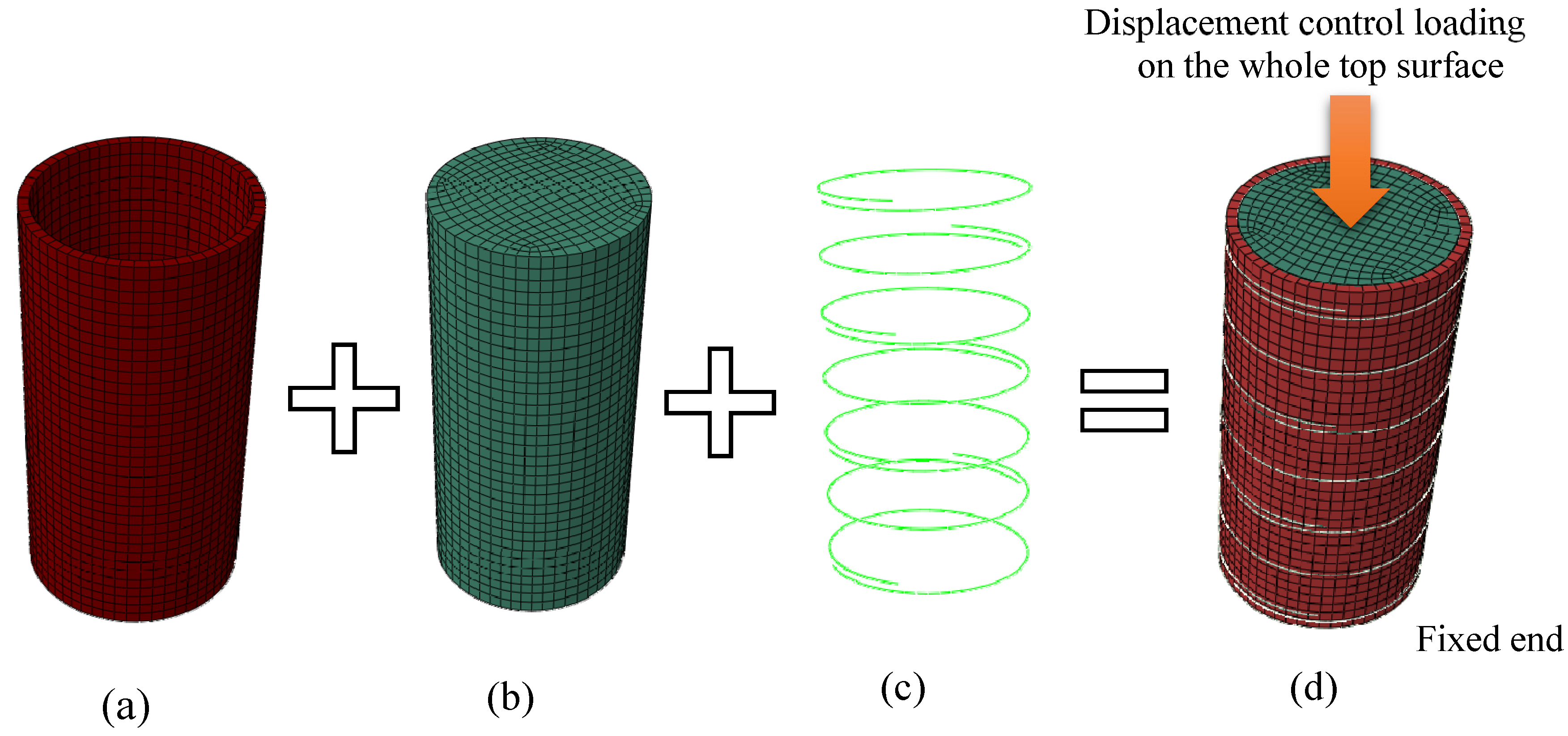
2.1. Mesh and Element Type
2.2. Boundary and Loading Conditions
2.3. Interactions
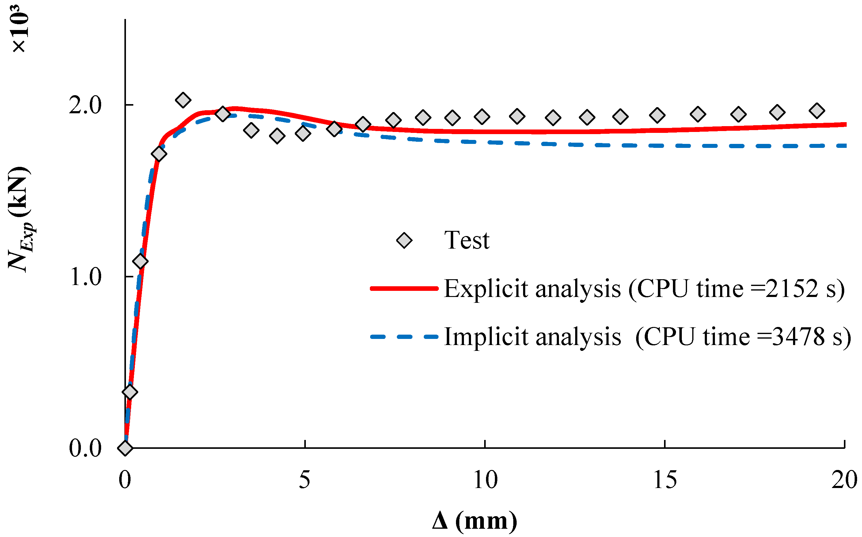
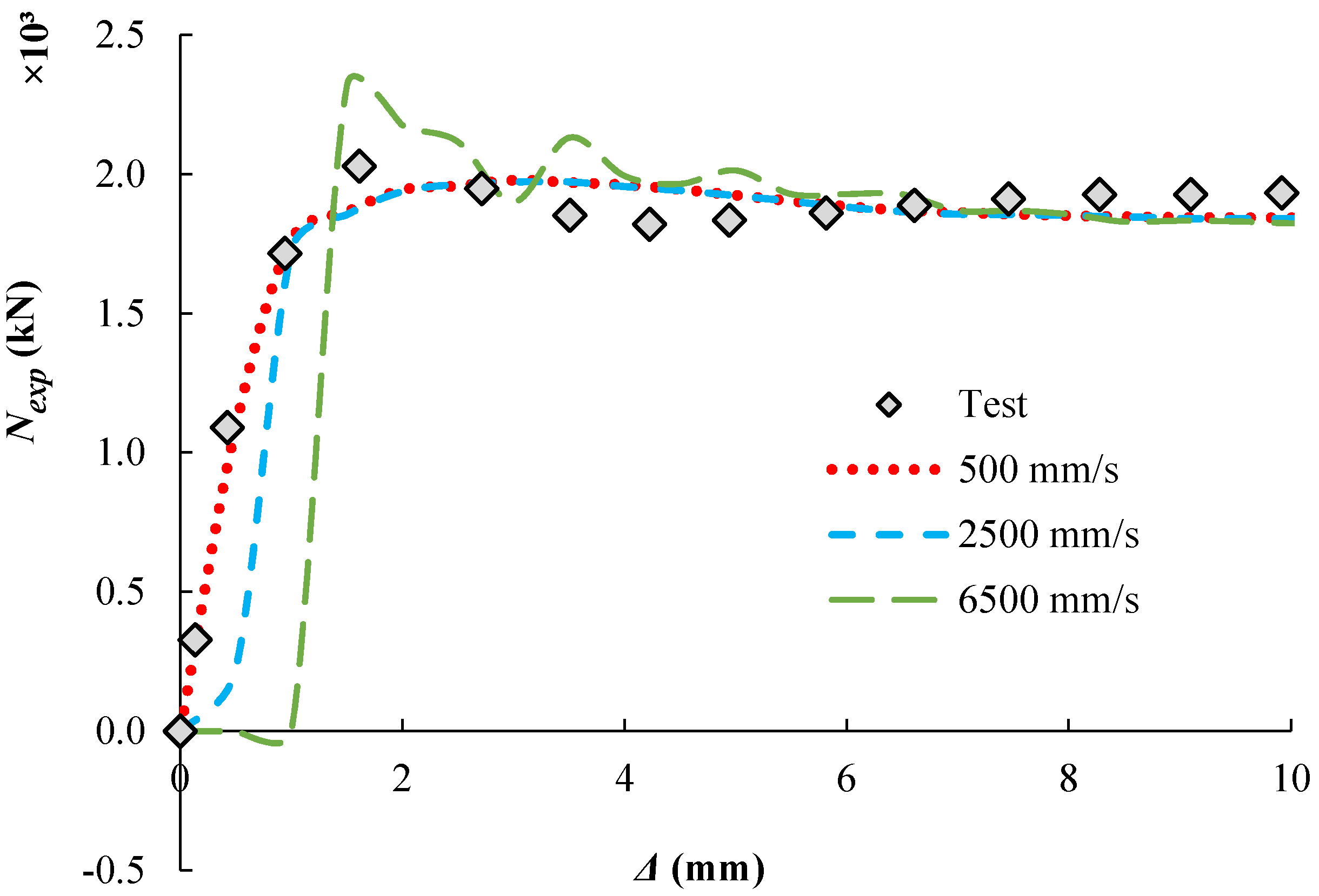
2.4. Step Type
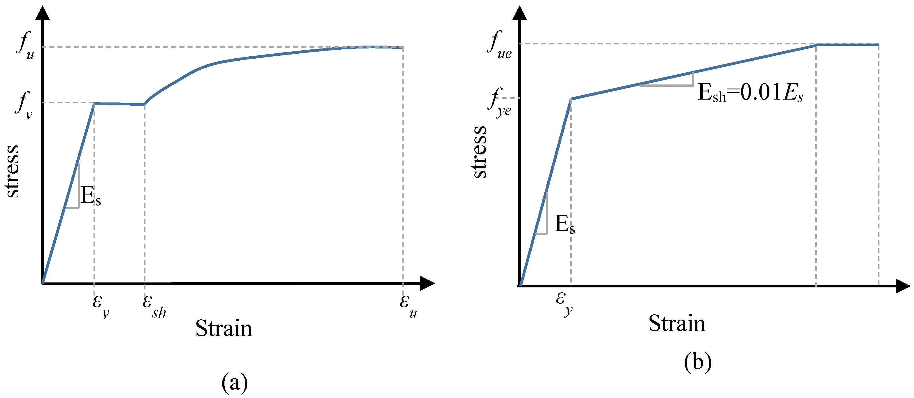
2.5. Material Model of the Steel Tube
- ◾
- ◾
- ◾
2.6. Material Model of the Steel External Confinements
2.7. Material Model of the Concrete Core
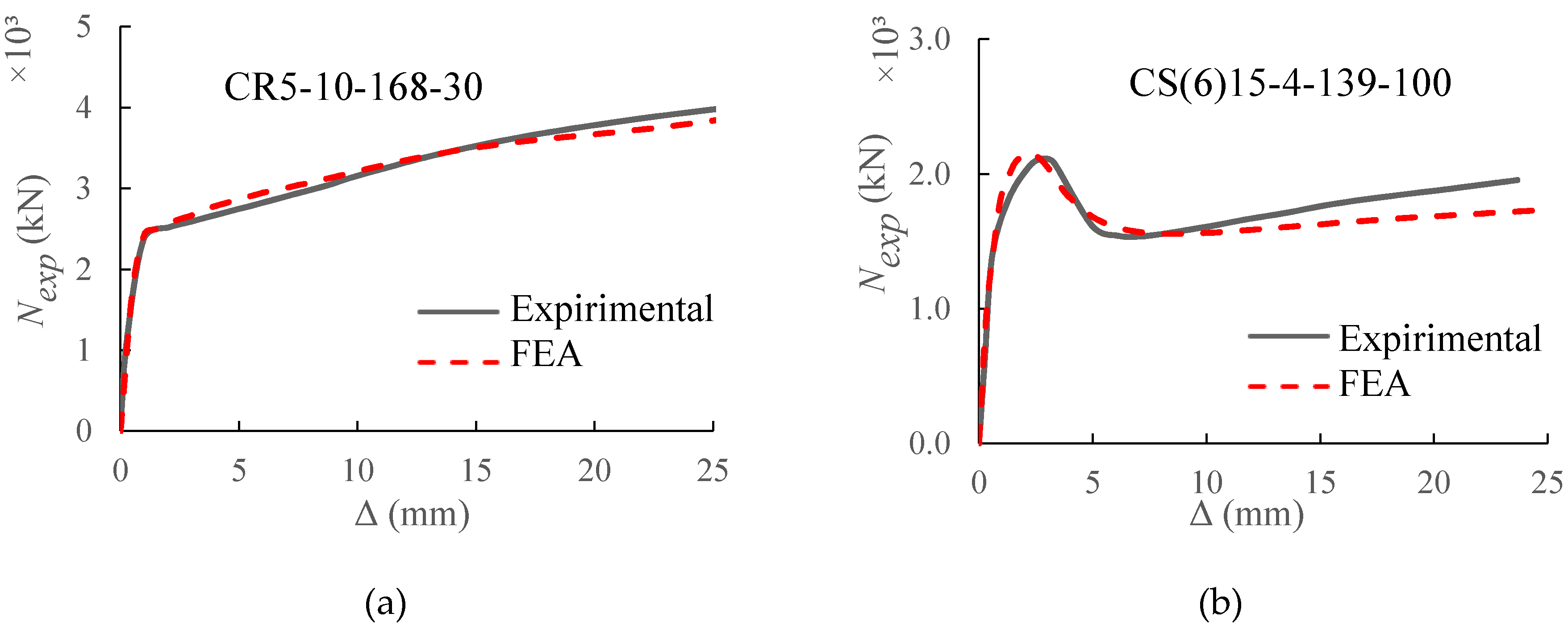
2.8. Model Validation
3. Analytical Behaviour
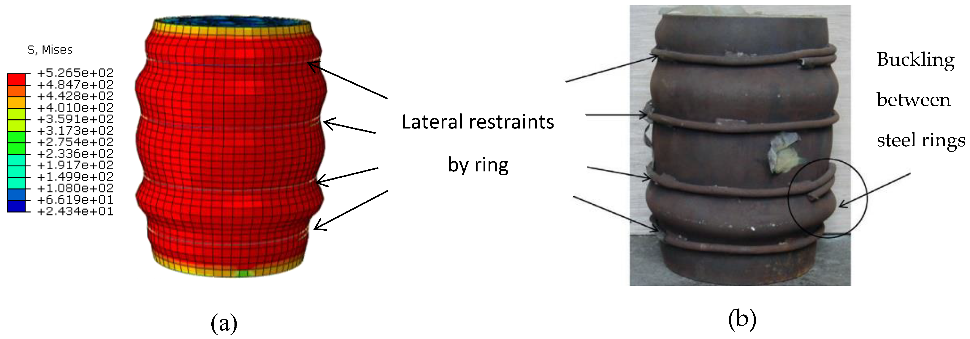
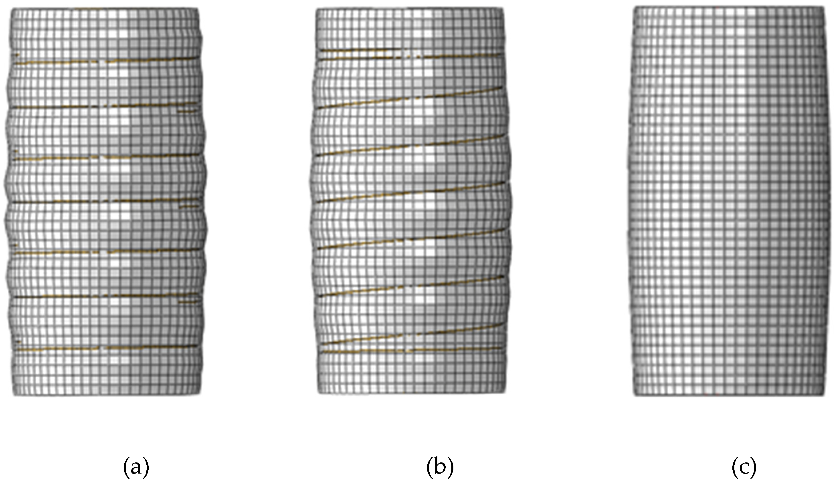
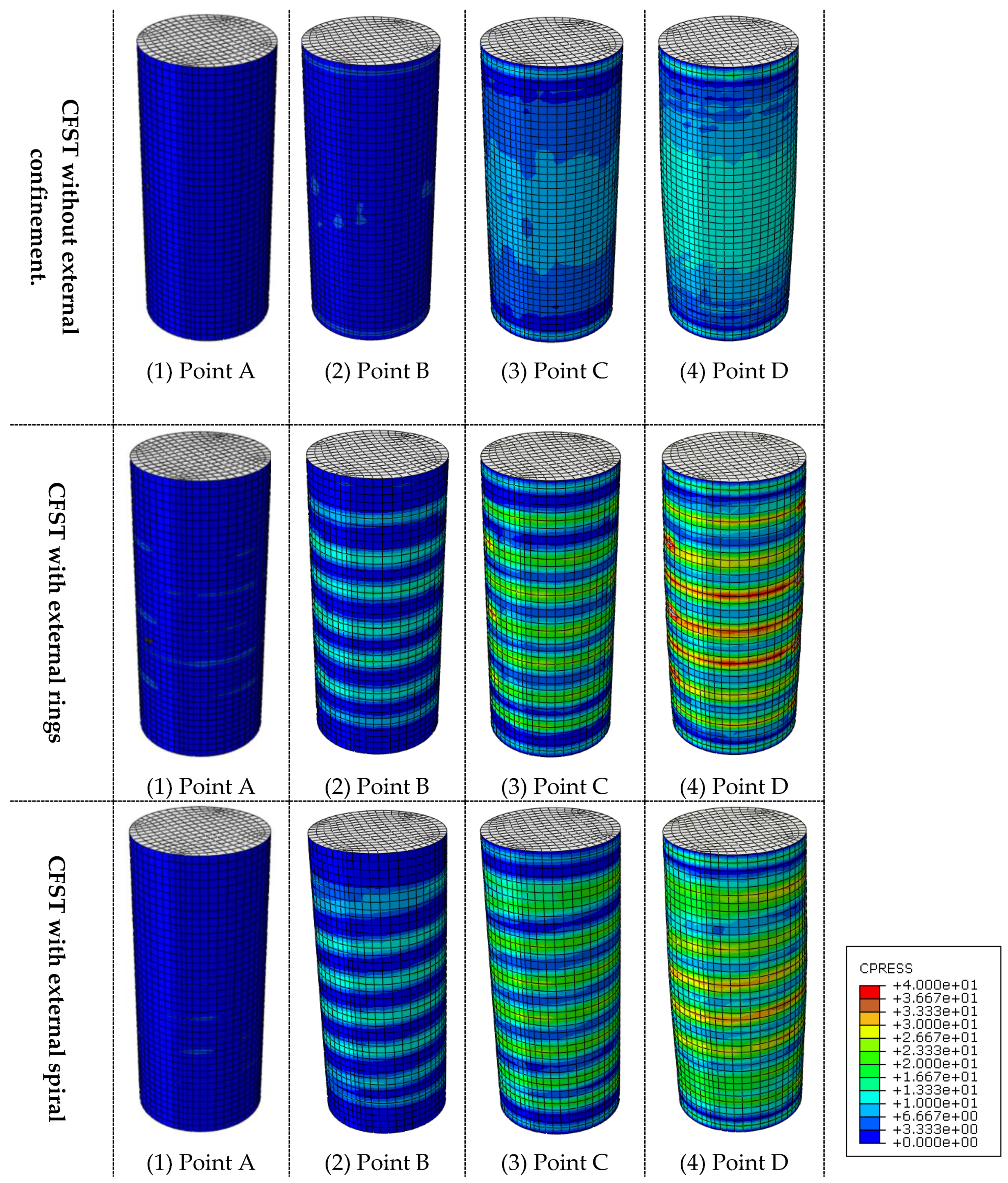
3.1. Typical Failure Mode
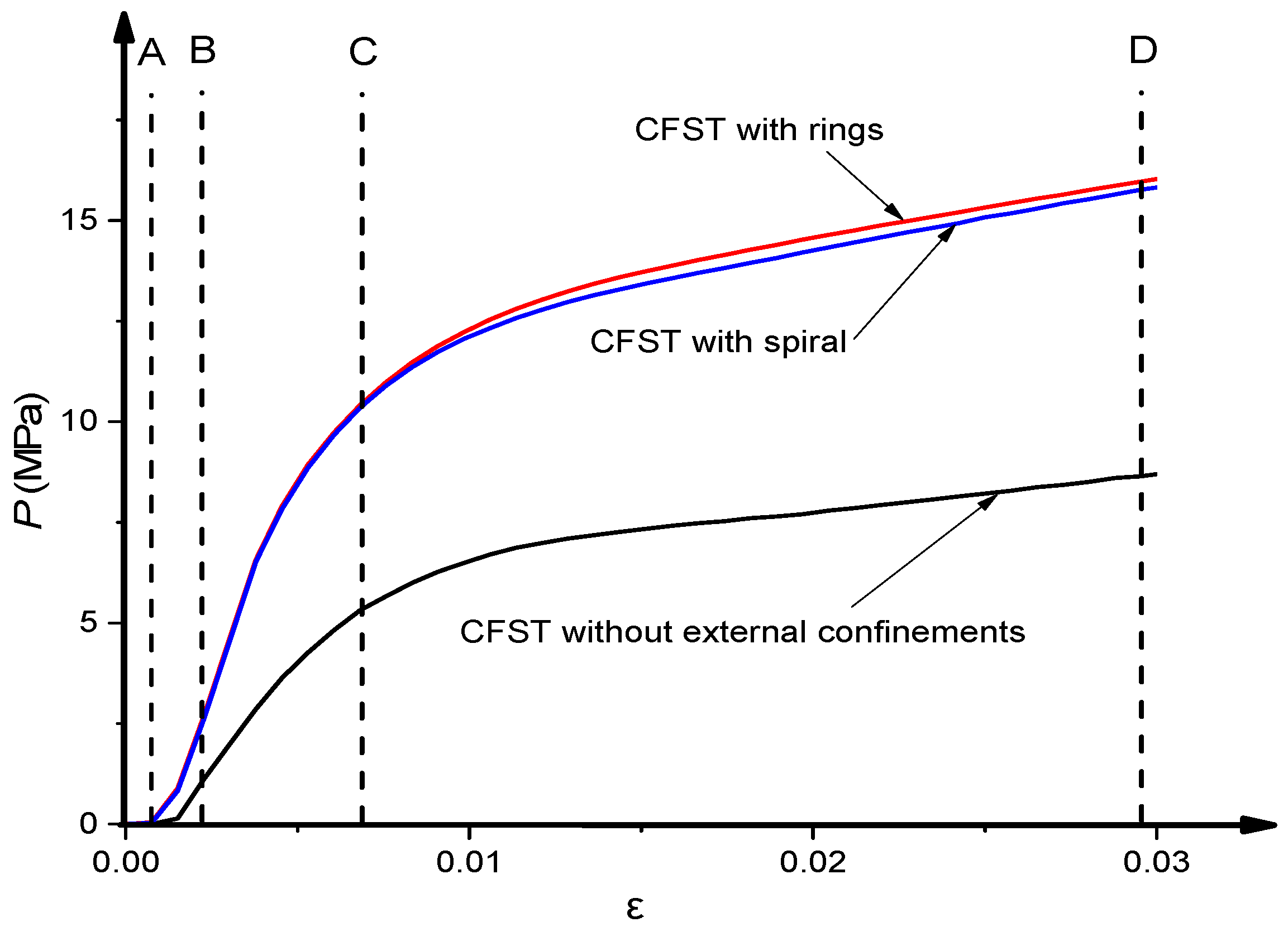
3.2. Load-Deformation Curves
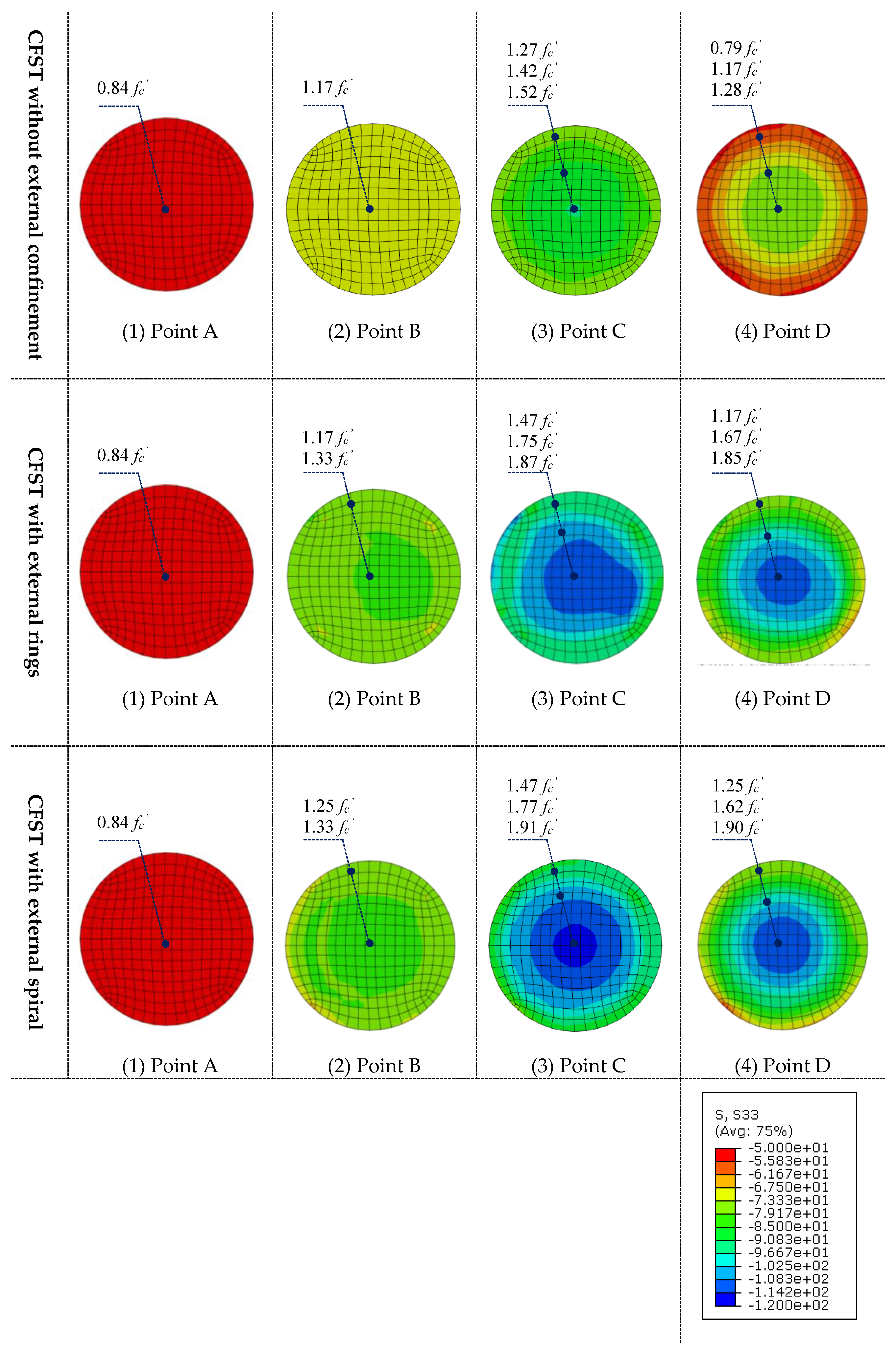
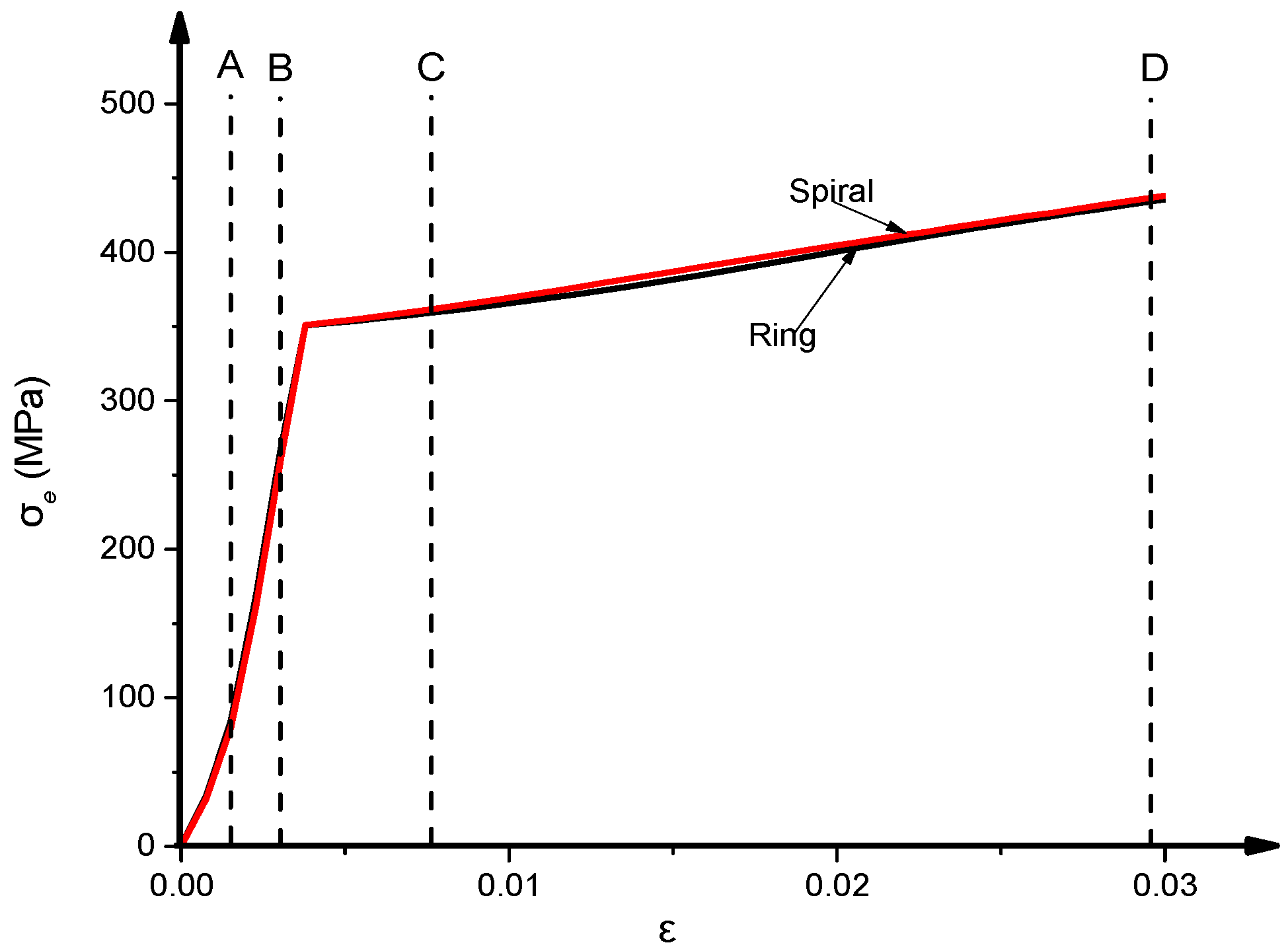
3.3. Interaction Behaviour
4. Parametric Analysis
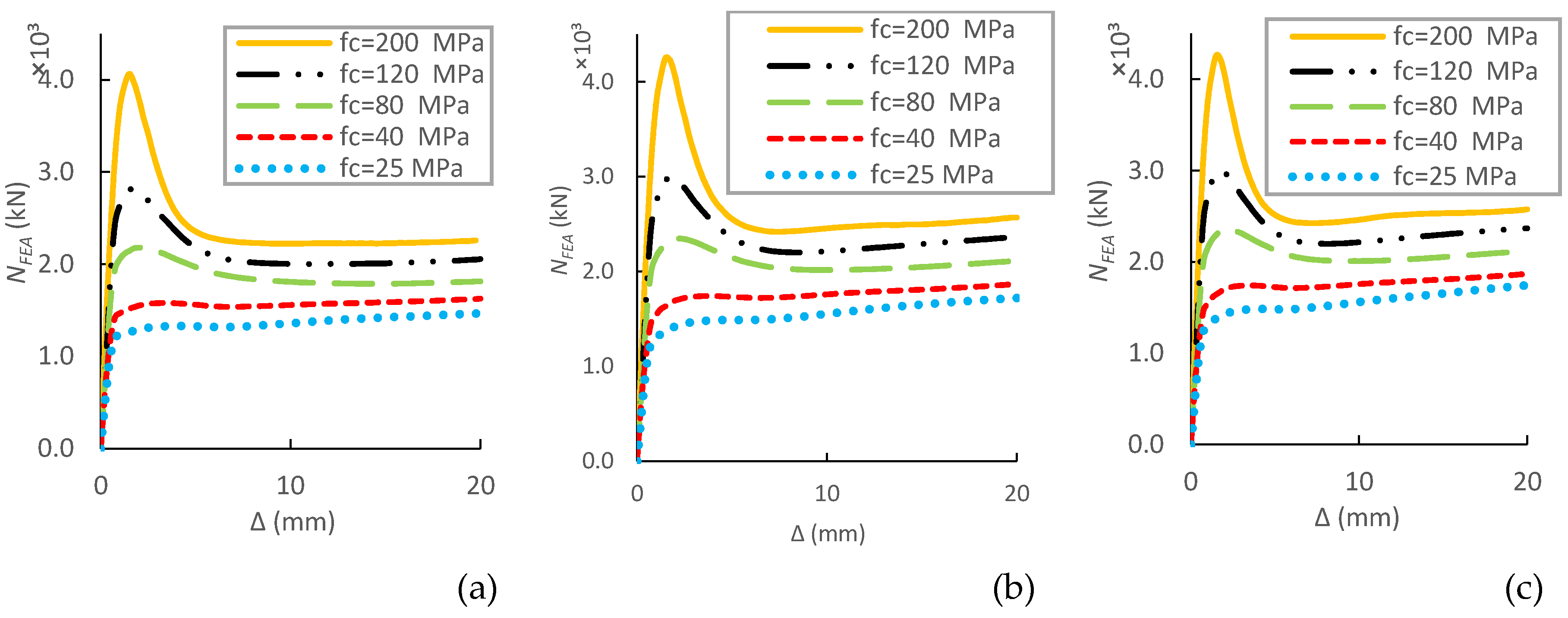
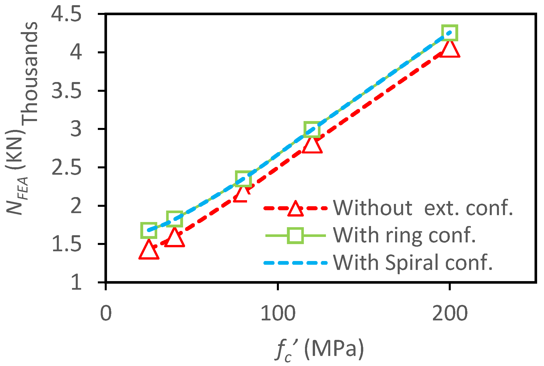
4.1. Influence of Concrete Grade
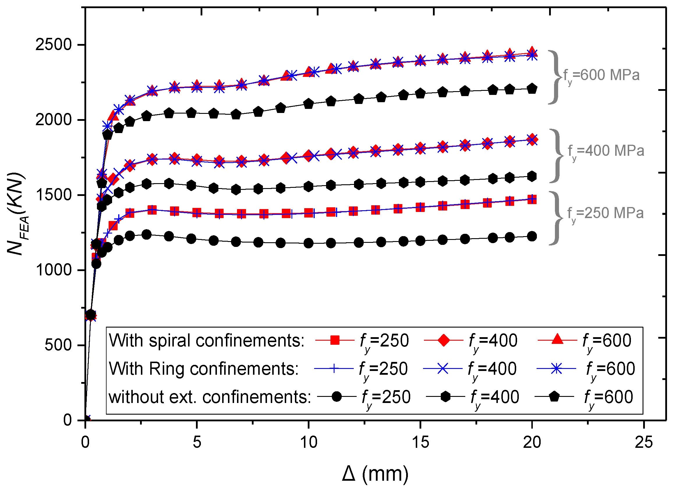
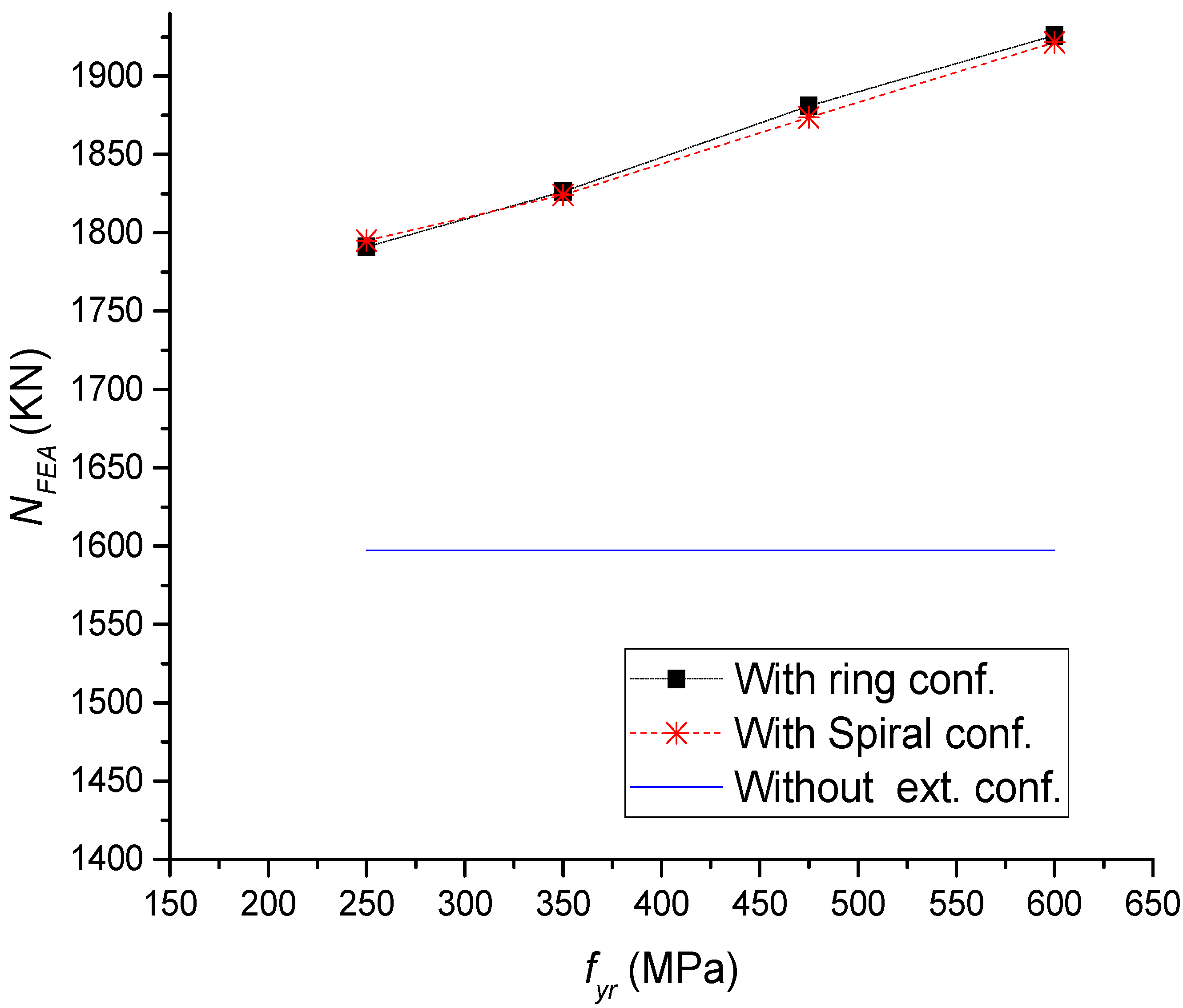
4.2. Influence of Steel Tube Grade
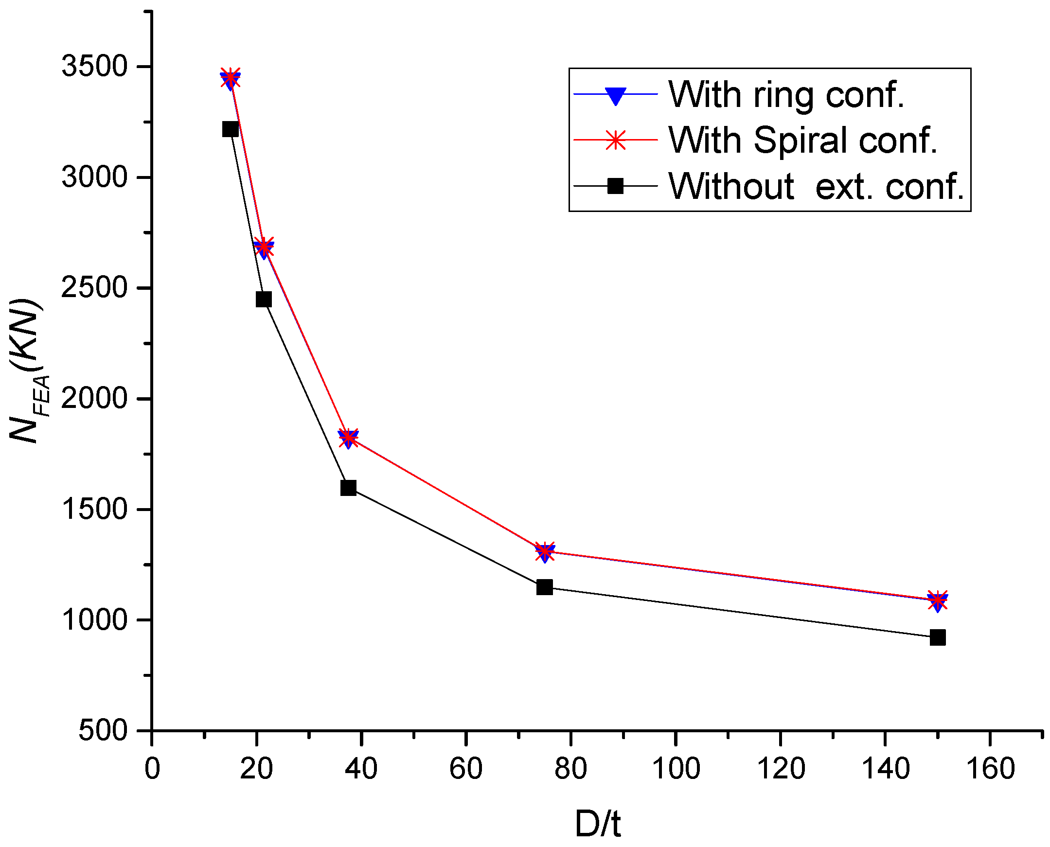
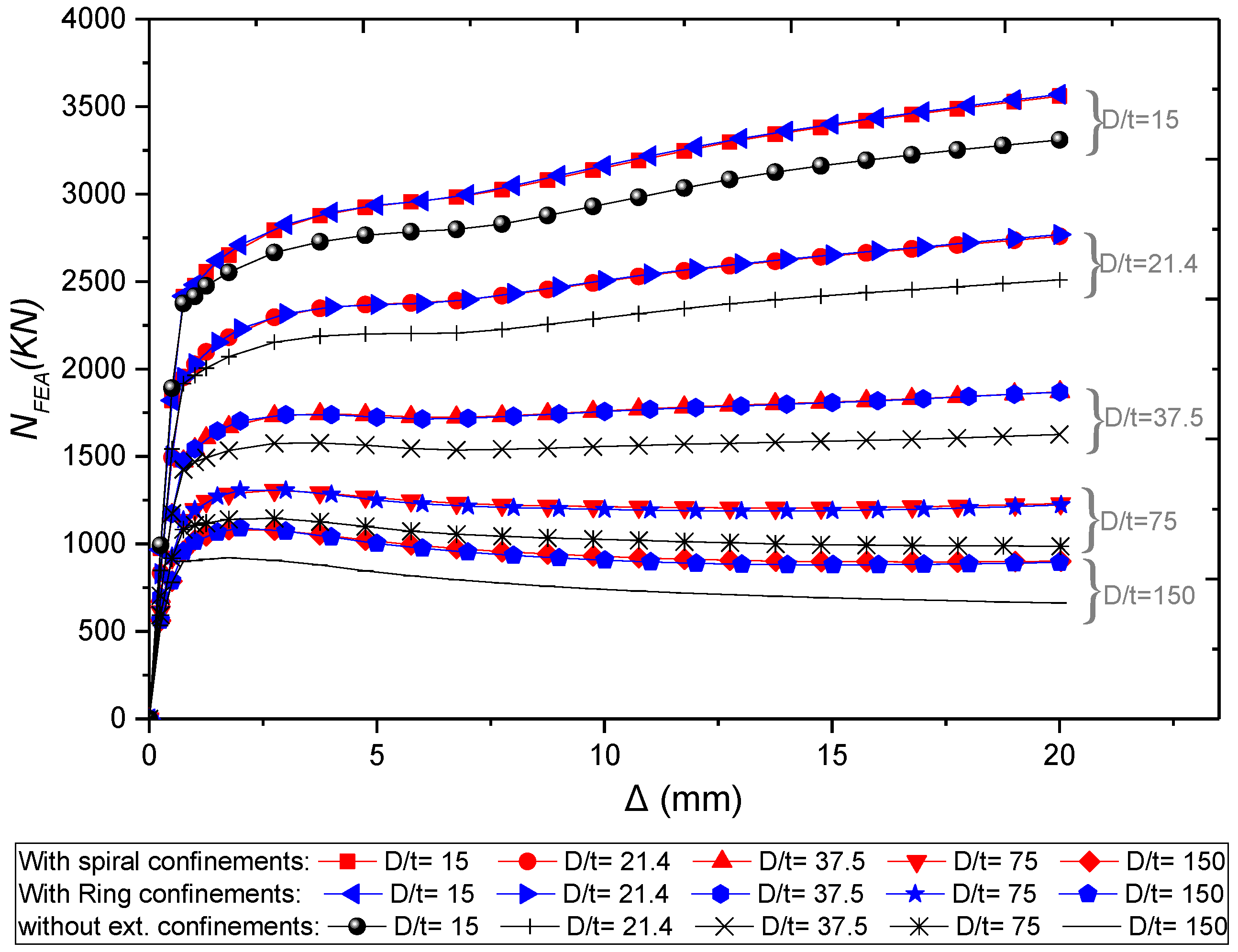
4.3. Influence of Diameter-to-Thickness (D/t) Ratio
4.4. Influence of External Confinements Grade
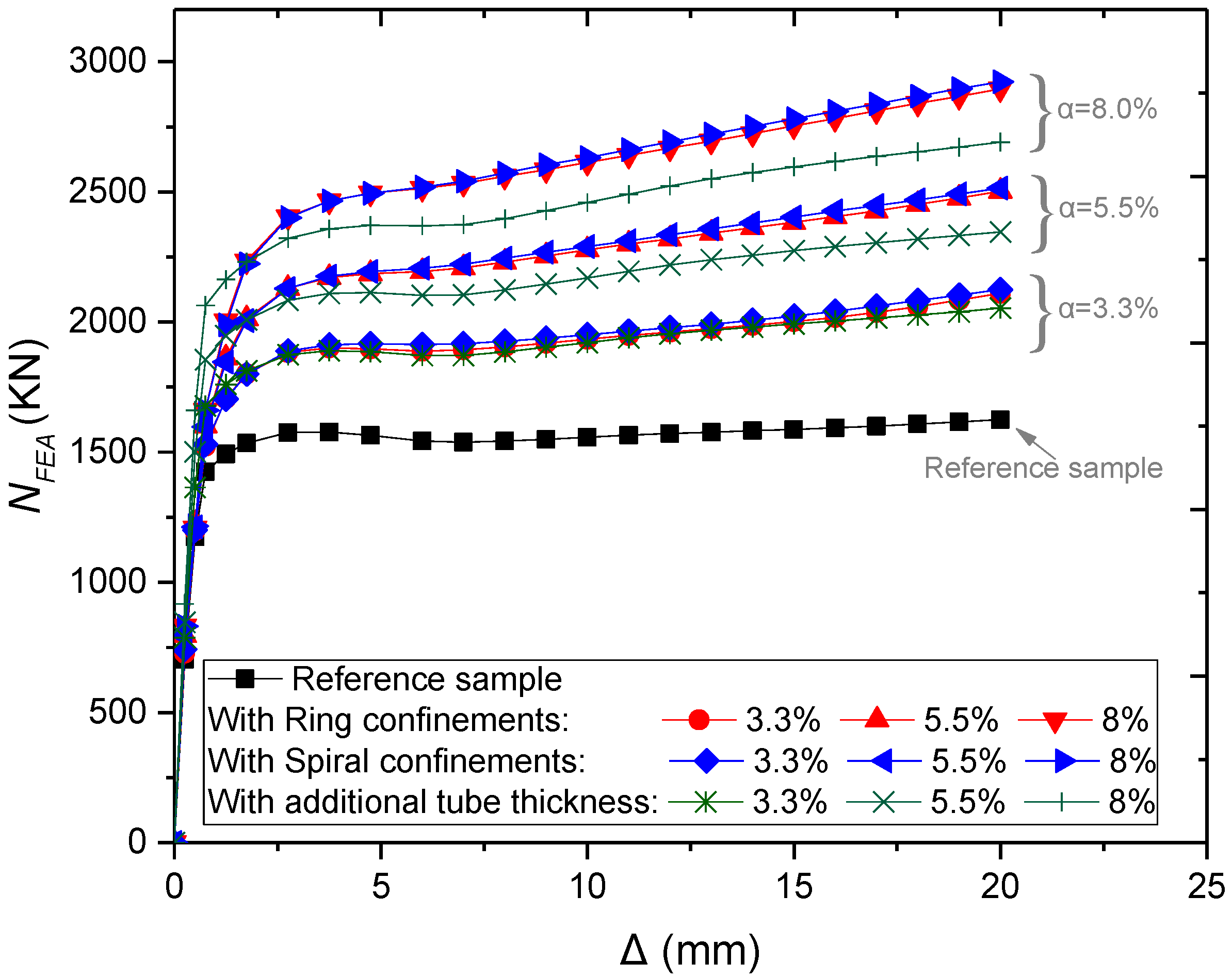
4.5. Influence of Steel Ratio (α)
5. Prediction of the Ultimate Strength
6. Conclusions
- A finite element (FE) model was established to examine the behaviour of circular CFST stub columns with and without external steel confinement which is subjected to axial loading. The accuracy of FE results was validated based on previous experimental tests. Good agreement was achieved between the numerical and test results.
- This study described the analytical behaviour of CFSTs with and without external steel confinements, and the axial load (N) and axial strain (ε) relationship was divided into four main stages. During the elastic stage, N-ε curves were almost the same for CFSTs with and without external confinements. After that, CFSTs with external confinement show higher strength and better ductility.
- The presence of external confinements can remarkably improve the steel-concrete interaction stress, especially after the elastic stage.
- According to the results parametric analysis, the increase of concrete strength, steel tube yielding strength, external confinements yielding strength, and total steel ratio besides the decrease of diameter-to-thickness ratio lead to enhance the structural performance of CFST columns at varying rates.
- Under axial loading, the use of external steel confinements in CFST can provide better performance than increasing the thickness of steel tube when using the same steel ratio.
- A simplified design method was developed to accurately estimate the ultimate strength of CFST columns with and without external steel confinement.
- Future investigation needs to consider the influence of different slenderness ratio, cross-sectional shapes, and materials of CFST columns with external steel confinements under different loading conditions.
Author Contributions
Funding
Conflicts of Interest
References
- Zhao, X.-L.; Han, L.-H.; Lu, H. Concrete-Filled Tubular Members and Connections; Spon Press: London, UK, 2010. [Google Scholar]
- Zheng, J.; Wang, J. Concrete-Filled Steel Tube Arch Bridges in China. Engineering 2018, 4, 143–155. [Google Scholar] [CrossRef]
- Kodur, V.K.R. Performance-based fire resistance design of concrete-filled steel columns. J. Constr. Steel Res. 1999, 51, 21–36. [Google Scholar] [CrossRef]
- Liao, F.-Y.; Han, L.-H.; He, S.-H. Behavior of CFST short column and beam with initial concrete imperfection: Experiments. J. Constr. Steel Res. 2011, 67, 1922–1935. [Google Scholar] [CrossRef]
- Tao, Z.; Song, T.Y.; Uy, B.; Han, L.H. Bond behavior in concrete-filled steel tubes. J. Constr. Steel Res. 2016, 120, 81–93. [Google Scholar] [CrossRef]
- Xu, C.; Huang, C.; Jiang, D.; Song, Y. Push-out test of pre-stressing concrete filled circular steel tube columns by means of expansive cement. Constr. Build. Mater. 2009, 23, 491–497. [Google Scholar] [CrossRef]
- Wang, Y.; Geng, Y.; Ranzi, G.; Zhang, S. Time-dependent behaviour of expansive concrete-filled steel tubular columns. J. Constr. Steel Res. 2011, 67, 471–483. [Google Scholar] [CrossRef]
- He, L.; Zhao, Y.; Lin, S. Experimental study on axially compressed circular CFST columns with improved confinement effect. J. Constr. Steel Res. 2018, 140, 74–81. [Google Scholar] [CrossRef]
- Kwan, A.K.H.; Dong, C.X.; Ho, J.C.M. Axial and lateral stress–strain model for circular concrete-filled steel tubes with external steel confinement. Eng. Struct. 2016, 117, 528–541. [Google Scholar] [CrossRef]
- Ge, H.; Usami, T. Strength of Concrete-Filled Thin-Walled Steel Box Columns: Experiment. J. Struct. Eng. 1992, 118, 3036–3054. [Google Scholar] [CrossRef]
- Kitada, T. Ultimate strength and ductility of state-of-the-art concrete-filled steel bridge piers in Japan. Eng. Struct. 1998, 20, 347–354. [Google Scholar] [CrossRef]
- Tao, Z.; Han, L.H.; Wang, Z.B. Experimental behaviour of stiffened concrete-filled thin-walled hollow steel structural (HSS) stub columns. J. Constr. Steel Res. 2005, 61, 962–983. [Google Scholar] [CrossRef]
- Cai, J.; He, Z.-Q. Axial load behavior of square CFT stub column with binding bars. J. Constr. Steel Res. 2006, 62, 472–483. [Google Scholar] [CrossRef]
- Hsu, H.L.; Juang, J.L. Performance of thin-walled box columns strengthened with internal braces. Thin-Walled Struct. 2000, 37, 241–258. [Google Scholar] [CrossRef]
- Lai, M.H.; Ho, J.C.M. Uni-axial Compression Test of Concrete-filled-steel-tube Columns Confined by Tie Bars. Procedia Eng. 2013, 57, 662–669. [Google Scholar] [CrossRef] [Green Version]
- Bahrami, A.; Badaruzzaman, W.H.W.; Osman, S.A. Behaviour of stiffened concrete-filled steel composite (CFSC) stub columns. Lat. Am. J. Solids Struct. 2013, 10, 409–440. [Google Scholar] [CrossRef] [Green Version]
- Bahrami, A.; Wan Badaruzzaman, W.H.; Osman, S.A. Investigation of concrete-filled steel composite (CFSC) stub columns with bar stiffeners. J. Civ. Eng. Manag. 2013, 19, 433–446. [Google Scholar] [CrossRef]
- Dabaon, M.; El-Khoriby, S.; El-Boghdadi, M.; Hassanein, M.F. Confinement effect of stiffened and unstiffened concrete-filled stainless steel tubular stub columns. J. Constr. Steel Res. 2009, 65, 1846–1854. [Google Scholar] [CrossRef]
- Zhang, Y.; Xu, C.; Lu, X. Experimental study of hysteretic behaviour for concrete-filled square thin-walled steel tubular columns. J. Constr. Steel Res. 2007, 63, 317–325. [Google Scholar] [CrossRef]
- Ganesh Prabhu, G.; Sundarraja, M.C. Behaviour of concrete filled steel tubular (CFST) short columns externally reinforced using CFRP strips composite. Constr. Build. Mater. 2013, 47, 1362–1371. [Google Scholar] [CrossRef]
- Lai, M.H.; Ho, J.C.M. Confinement effect of ring-confined concrete-filled-steel-tube columns under uni-axial load. Eng. Struct. 2014, 67, 123–141. [Google Scholar] [CrossRef]
- Lai, M.H.; Ho, J.C.M. Effect of continuous spirals on uni-axial strength and ductility of CFST columns. J. Constr. Steel Res. 2015, 104, 235–249. [Google Scholar] [CrossRef]
- Al Zand, A.W.; Badaruzzaman, W.H.W.; Mutalib, A.A.; Hilo, S.J. The enhanced performance of CFST beams using different strengthening schemes involving unidirectional CFRP sheets: An experimental study. Eng. Struct. 2016, 128, 184–198. [Google Scholar] [CrossRef]
- Wang, J.; Shen, Q.; Wang, F.; Wang, W. Experimental and analytical studies on CFRP strengthened circular thin-walled CFST stub columns under eccentric compression. Thin-Walled Struct. 2018, 127, 102–119. [Google Scholar] [CrossRef]
- ABAQUS Standard. User’s Manual; Version 6.14; Dassault Systèmes Corp.: Providence, RI, USA, 2014. [Google Scholar]
- Alatshan, F.; Mashiri, F.R. Finite Element Modeling of Concrete-Filled Steel Tubes: Review and Recent Developments. In Applied Mechanics and Materials; Trans Tech Publications: Kapellweg, Switzerland, 2013. [Google Scholar]
- Tao, Z.; Wang, Z.-B.; Yu, Q. Finite element modelling of concrete-filled steel stub columns under axial compression. J. Constr. Steel Res. 2013, 89, 121–131. [Google Scholar] [CrossRef]
- Hassanein, M.F.; Elchalakani, M.; Karrech, A.; Patel, V.I.; Yang, B. Behaviour of Concrete-filled Double-skin Short Columns Under Compression Through Finite Element Modelling: SHS Outer and SHS Inner Tubes. Structures 2018, 14, 358–375. [Google Scholar] [CrossRef]
- Yun, X.; Gardner, L. Stress-strain curves for hot-rolled steels. J. Constr. Steel Res. 2017, 133, 36–46. [Google Scholar] [CrossRef]
- Lai, M. Behaviour of CFST Columns with External Confinement under Uni-Axial Compression. Ph.D. Thesis, The University of Hong Kong, Hong Kong, China, 2015. [Google Scholar]
- Tao, Z.; Wang, X.-Q.; Uy, B. Stress-Strain Curves of Structural and Reinforcing Steels after Exposure to Elevated Temperatures. J. Mater. Civ. Eng. 2013, 25, 1306–1316. [Google Scholar] [CrossRef]
- Pagoulatou, M.; Sheehan, T.; Dai, X.H.; Lam, D. Finite element analysis on the capacity of circular concrete-filled double-skin steel tubular (CFDST) stub columns. Eng. Struct. 2014, 72, 102–112. [Google Scholar] [CrossRef] [Green Version]
- Papanikolaou, V.K.; Kappos, A.J. Confinement-sensitive plasticity constitutive model for concrete in triaxial compression. Int. J. Solids Struct. 2007, 44, 7021–7048. [Google Scholar] [CrossRef] [Green Version]
- American Concrete Institute. Building Code Requirements for Structural Concrete (ACI 318-11); American Concrete Institute: Farmington Hills, MI, USA, 2011. [Google Scholar]
- Bahrami, A.; Wan Badaruzzaman, W.H.; Osman, S.A. Performance of axially loaded tapered concrete-filled steel composite slender columns. J. Civ. Eng. Manag. 2013, 19, 705–717. [Google Scholar] [CrossRef]
- Bahrami, A.; Badaruzzaman, W.H.W.; Osman, S.A. Structural behaviour of tapered concrete-filled steel composite (TCFSC) columns subjected to eccentric loading. Comput. Concr. 2012, 9, 403–426. [Google Scholar] [CrossRef]
- Hong, K.-N.; Han, S.-H.; Yi, S.-T. High-strength concrete columns confined by low-volumetric-ratio lateral ties. Eng. Struct. 2006, 28, 1346–1353. [Google Scholar] [CrossRef]
- Cusson, D.; Paultre, P. High-Strength Concrete Columns Confined by Rectangular Ties. J. Struct. Eng. 1994, 120, 783–804. [Google Scholar] [CrossRef]
- Mander, J.B.; Priestley, M.J.N.; Park, R. Theoretical Stress-Strain Model for Confined Concrete. J. Struct. Eng. 1988, 114, 1804–1826. [Google Scholar] [CrossRef] [Green Version]
- Richart, F.E.; Brandtzaeg, A.; Brown, R.L. A Study of the Failure of Concrete under Combined Compressive Stresses; University of Illinois at Urbana Champaign: Champaign, IL, USA, 1928. [Google Scholar]


| Loading Rate | Mass Scaling Factor | Increment | CPU Time (s) |
|---|---|---|---|
| 6500 mm/s | 10 | 5048 | 134 |
| 2500 mm/s | 10 | 12558 | 306 |
| 500 mm/s | 10 | 62190 | 2152 |
| 500 mm/s | 5 | 87758 | 2521 |
| 500 mm/s | 30 | 35985 | 1279 |
| Group No. | Specimens | Nexp (kN) | NFEA (kN) | |
|---|---|---|---|---|
| R1 | CR5-5-168-30 | 2836 | 2736 | 1.037 |
| CR10-5-168-30 | 2387 | 2464 | 0.969 | |
| CR12.5-5-168-30 | 2250 | 2335 | 0.964 | |
| CR15-5-168-30 | 2205 | 2327 | 0.948 | |
| CR20-5-168-30 | 2142 | 2239 | 0.957 | |
| CN0-5-168-30 | 1908 | 2024 | 0.943 | |
| R2 | CR5-8-168-30 | 3536 | 3550 | 0.996 |
| CR10-8-168-30 | 3217 | 3358 | 0.958 | |
| CR12.5-8-168-30 | 3163 | 3309 | 0.956 | |
| CR15-8-168-30 | 3117 | 3300 | 0.945 | |
| CR20-8-168-30 | 2905 | 3300 | 0.880 | |
| CN0-8-168-30 | 2810 | 3093 | 0.908 | |
| R3 | CR5-10-139-30 | 2791 | 2733 | 1.021 |
| CR10-10-139-30 | 2530 | 2621 | 0.965 | |
| CR15-10-139-30 | 2473 | 2584 | 0.957 | |
| CR20-10-139-30 | 2511 | 2550 | 0.985 | |
| CN0-10-139-30 | 2510 | 2495 | 1.006 | |
| R4 | CR5-10-168-30 | 3616 | 3874 | 0.934 |
| CR10-10-168-30 | 3364 | 3702 | 0.909 | |
| CR12.5-10-168-30 | 3346 | 3707 | 0.903 | |
| CR15-10-168-30 | 3273 | 3715 | 0.881 | |
| CR20-10-168-30 | 3278 | 3671 | 0.893 | |
| CN0-10-168-30 | 3232 | 3566 | 0.906 | |
| R5 | CR5-10-139-50 | 3038 | 2966 | 1.024 |
| CR10-10-139-50 | 2866 | 2842 | 1.009 | |
| CR15-10-139-50 | 2849 | 2831 | 1.006 | |
| CR20-10-139-50 | 2835 | 2772 | 1.023 | |
| CN0-10-139-50 | 2750 | 2695 | 1.020 | |
| R6 | CR5-5-168-80 | 3643 | 3475 | 1.048 |
| CR10-5-168-80 | 3205 | 3166 | 1.012 | |
| CR12.5-5-168-80 | 3178 | 3052 | 1.041 | |
| CR15-5-168-80 | 3079 | 3067 | 1.004 | |
| CR20-5-168-80 | 3149 | 2960 | 1.064 | |
| CN0-5-168-80 | 2926 | 2809 | 1.042 | |
| R7 | CR5-8-168-80 | 3749 | 3720 | 1.008 |
| CR10-8-168-80 | 3317 | 3489 | 0.951 | |
| CR12.5-8-168-80 | 3600 | 3589 | 1.003 | |
| CR15-8-168-80 | 3218 | 3443 | 0.935 | |
| CR20-8-168-80 | 3171 | 3459 | 0.917 | |
| CN0-8-168-80 | 3101 | 3278 | 0.946 | |
| R8 | CR5-10-139-90 | 3333 | 3245 | 1.027 |
| CR10-10-139-90 | 3022 | 3108 | 0.972 | |
| CR15-10-139-90 | 3047 | 3056 | 0.997 | |
| CR20-10-139-90 | 3120 | 3018 | 1.034 | |
| CN0-10-139-90 | 2966 | 2944 | 1.007 | |
| R9 | CR5-10-168-90 | 4396 | 4635 | 0.948 |
| CR10-10-168-90 | 4130 | 4439 | 0.930 | |
| CR12.5-10-168-90 | 4285 | 4426 | 0.968 | |
| CR15-10-168-90 | 4361 | 4420 | 0.987 | |
| CR20-10-168-90 | 4063 | 4370 | 0.930 | |
| CN0-10-168-90 | 3930 | 4284 | 0.917 | |
| R10 | CR5-5-114-120 | 2340 | 2195 | 1.066 |
| CR10-5-114-120 | 2167 | 2047 | 1.059 | |
| CR12.5-5-114-120 | 2065 | 2016 | 1.024 | |
| CR15-5-114-120 | 2110 | 2002 | 1.054 | |
| CR20-5-114-120 | 1977 | 1987 | 0.995 | |
| CN0-5-114-120 | 1875 | 1881 | 0.997 | |
| R11 | CR5-10-139-120 | 3621 | 3413 | 1.061 |
| CR10-10-139-120 | 3207 | 3305 | 0.970 | |
| CR15-10-139-120 | 3180 | 3272 | 0.972 | |
| CR20-10-139-120 | 3301 | 3218 | 1.026 | |
| CN0-10-139-120 | 3208 | 3164 | 1.014 |
| Group No. | Specimens | Nexp (kN) | NFEA (kN) | |
|---|---|---|---|---|
| S1 | CS(6)10-4-139-30 | 1403 | 1274 | 1.112 |
| CS(6)15-4-139-30 | 1278 | 1235 | 1.046 | |
| CS(8)20-4-139-30 | 1307 | 1298 | 1.017 | |
| CS(6)20-4-139-30 | 1211 | 1219 | 1.004 | |
| CN0-4-139-30 | 1122 | 1098 | 1.022 | |
| S2 | CS(8)10-4-139-50 | 1770 | 1583 | 1.118 |
| CS(6)10-4-139-50 | 1512 | 1459 | 1.036 | |
| CS(8)15-4-139-50 | 1665 | 1516 | 1.099 | |
| CS(6)15-4-139-50 | 1496 | 1420 | 1.054 | |
| CS(8)20-4-139-50 | 1518 | 1478 | 1.027 | |
| CS(6)20-4-139-50 | 1396 | 1583 | 1.118 | |
| CN0-4-139-50 | 1297 | 1302 | 0.996 | |
| S3 | CS(8)10-4-139-100 | 2398 | 1.083 | 1.085 |
| CS(6)10-4-139-100 | 2128 | 1.008 | 1.010 | |
| CS(8)15-4-139-100 | 2109 | 0.980 | 0.982 | |
| CS(6)15-4-139-100 | 2086 | 1.009 | 1.011 | |
| CS(8)20-4-139-100 | 2171 | 1.021 | 1.023 | |
| CS(6)20-4-139-100 | 2161 | 1.054 | 1.056 | |
| CN0-4-139-100 | 2070 | 1949 | 1.062 | |
| S4 | CS(8)10-4-139-120 | 2640 | 1.057 | 1.059 |
| CS(6)10-4-139-120 | 2488 | 1.047 | 1.048 | |
| CS(8)15-4-139-120 | 2566 | 1.058 | 1.060 | |
| CS(6)15-4-139-120 | 2476 | 1.056 | 1.057 | |
| CS(8)20-4-139-120 | 2577 | 1.077 | 1.078 | |
| CS(6)20-4-139-120 | 2528 | 1.089 | 1.090 | |
| CN0-4-139-120 | 2390 | 2226 | 1.074 |
© 2019 by the authors. Licensee MDPI, Basel, Switzerland. This article is an open access article distributed under the terms and conditions of the Creative Commons Attribution (CC BY) license (http://creativecommons.org/licenses/by/4.0/).
Share and Cite
Alatshan, F.; Osman, S.A.; Mashiri, F.; Hamid, R. Explicit Simulation of Circular CFST Stub Columns with External Steel Confinement under Axial Compression. Materials 2020, 13, 23. https://doi.org/10.3390/ma13010023
Alatshan F, Osman SA, Mashiri F, Hamid R. Explicit Simulation of Circular CFST Stub Columns with External Steel Confinement under Axial Compression. Materials. 2020; 13(1):23. https://doi.org/10.3390/ma13010023
Chicago/Turabian StyleAlatshan, Faesal, Siti Aminah Osman, Fidelis Mashiri, and Roszilah Hamid. 2020. "Explicit Simulation of Circular CFST Stub Columns with External Steel Confinement under Axial Compression" Materials 13, no. 1: 23. https://doi.org/10.3390/ma13010023