Article

Effect of Optimization of TiO2 Electron Transport Layer on Performance of Perovskite Solar Cells with Rough FTO Substrates

1
Beijing Advanced Innovation Center for Materials Genome Engineering, Research Center for Sensor Technology, Beijing Key Laboratory for Sensor, MOE Key Laboratory for Modern Measurement and Control Technology, School of Automation, Beijing Information Science and Technology University, Jianxiangqiao Campus, Beijing 100101, China
2
State Key Laboratory on Integrated Optoelectronics, Institute of Semiconductors, Chinese Academy of Sciences, Beijing 100083, China
3
Center of Materials Science and Optoelectronics Engineering, University of Chinese Academy of Sciences, Beijing 100049, China
*
Authors to whom correspondence should be addressed.
Materials 2020, 13(10), 2272; https://doi.org/10.3390/ma13102272
Submission received: 9 April 2020 / Revised: 8 May 2020 / Accepted: 11 May 2020 / Published: 15 May 2020

Abstract

:
The film quality of the electron transport layer (ETL) plays an important role in improving the performance of perovskite solar cells (PSCs). In order to reduce the effect of rough fluorine-doped SnO2 (FTO)substrate on the film quality of the TiO2 ETL, multiple cycles of spin-coating were employed to realize optimized TiO2 film and improve the performance of PSCs with rough FTO. The results show that TiO2 ETL was optimized most effectively using two spin-coating cycles, obtaining the best performance of PSCs with rough FTO. The carbon electrode-based PSCs were then demonstrated. Our work discusses the feasibility of low-quality rough FTO for the fabrication of PSCs and photodetectors to reduce costs.

1. Introduction

Solar cells are rapidly improving [1,2]. Recently, perovskite solar cells (PSCs) have drawn increasing attention due to their high power conversion efficiency (PCE), low cost, and facile preparation process [3,4,5,6,7,8]. A conventional planar heterojunction PSC is composed of a counter electrode (cathode), a hole transport layer, a perovskite layer, an electron transport layer (ETL), and a conductive glass substrate [9,10,11]. The ETL plays an important role in extracting electrons from the perovskite layer. It can prevent contact between the fluorine-doped SnO2 (FTO) and perovskite layer to avoid the recombination of electrons and holes, and reduce energy loss at the interface [11,12,13,14,15,16,17].
There are various preparation processes for the electron transport layer, including pyrolytic spraying [18], atomic layer deposition [19], thermal oxidation [20], electrochemical deposition, and liquid-phase spin-coating. The most widely used and simplest process is the liquid-phase spin-coating method [21,22,23].
It is essential to form appropriate ETL thickness to extract electrons and block holes effectively. Thick ETLs may cause high series resistance, which could deteriorate the performance of PSCs. Thin ETLs may not passivate all defects, and current leakage may occur. Any pinholes in ETLs can lead to shunt pathways and direct contact between the perovskite layer and conductive glass, causing high leakage current and severe carrier recombination at the interface [24]. It is reported that the loss of energy in PSCs corresponds to the recombination of electrons and holes in the carrier transport from perovskite to electrode [25,26]. Due to these restrictions, a single ETL cannot suppress the leakage current. It is generally known that charge recombination is highly responsible for reducing the energy conversion efficiency of PSCs. Many researchers have focused on the ETL of PSCs [16,17,27]. Some investigators have tried to add a new layer into the ETL to form a bilayer, which has been demonstrated as an effective way to modify the interfacial behavior and photovoltaic performance of PSCs. Chen et al. optimized the surface of ZnO with 3-aminopropanioc acid to improve the performance of solar cells [28]. Guo et al. added bathocuproine film as a hole-blocking layer between PCBM and Al to block holes in PSCs with an inverted structure [29]. They focus on the interface between the ETL and perovskite of the PSCs, giving little attention to the interface between ETLs and electrodes. Fang et al. deposited an MgO layer on the anode surface as a hole-blocking layer to avoid the recombination of electrons and holes [15].
In order to further improve the performance of the perovskite solar cell prepared with the liquid-phase spin-coating process, it is necessary to optimize the preparation process of the ETL to make the film uniform, non-porous, and more conductive [30].
However, the film is spin-coated on a rough FTO substrate, leading to uneven thickness, pinholes, and incomplete surface coverage of the TiO2 layer. This will result in contact between the perovskite light-absorption layer and the FTO substrate, resulting in the recombination of electrons and holes at the interface [31].
In our work, the problem of rough FTO substrate is solved by spin-coating TiO2 for different cycles on the FTO substrate. The TiO2 ETL was optimized to form a thin film without holes and cracks. The solar cell device prepared with the optimized TiO2 layer displayed the best electrical performance, with small series resistance and large shunt resistance obtained by SEM, XRD, and current–voltage (J–V) curve measurements. Finally, the carbon-electrode-based PSCs are demonstrated. Our work expands the feasibility of using low-quality FTO for the fabrication of PSCs and photodetectors to reduce costs.

2. Experiments

2.1. Materials

Acidic titanium dioxide solution (HH-TiOx), N,N-dimethylformamide (DMF), dimethyl sulfoxide (DMSO), and isopropyl alcohol (IPA) were purchased from Shanghai MaterWin New Materials Corp. (Shanghai, China). Methylammonium iodide (MAI), PbI2, fluorine-doped SnO2 (FTO) substrates, and spiro-MeOTAD solution were purchased from Xi’an Polymer Light Technology Corp. (Xi’an, China).

2.2. Device Fabrication

A flow schematic of the device fabrication is shown in Figure 1. The detailed experimental process is described as follows.

2.2.1. Cleaning FTO Glass

Surface treatment of the FTO substrate is essential before the deposition of any film to ensure complete coverage, and can severely affect the film deposition and properties. Malviya et al. demonstrated that rigorous cleaning processes yielded a clean FTO surface, and found that rigorous cleaning of the substrates prior to hematite deposition was crucial for achieving highly reproducible results [32].
In this work, we first cut the FTO rigid substrate into squares with an area of 1.5 cm × 1.5 cm. We placed the cut substrates with the conductive surface facing up in a single layer in a cleaned Petri dish, added an appropriate amount of deionized water and detergent to the Petri dish, then put them in an ultrasonic vibration cleaner for 20 min. We rinsed the substrate surfaces with a large amount of deionized water to remove substances that were soluble in the detergent. Following this, we added an appropriate amount of absolute ethanol to the Petri dish and ultrasonically cleaned the substrates for 20 min to remove various impurities on the surfaces that were easily soluble in absolute ethanol. We then rinsed the substrate surfaces with a large amount of deionized water to ensure no ethanol remained. Next, we added an appropriate amount of mixed solution of isopropanol, acetone, and deionized water with a volume ratio of 1:1:1 to the Petri dish, and ultrasonically washed the substrates for 20 min to remove various impurities on the surface that were easily soluble in isopropanol and acetone. After this process, the surfaces of the conductive substrate were washed with a large amount of deionized water to ensure no residual isopropanol and acetone remained. The cleaned substrates were dried in a constant-temperature drying box for 90 min, then placed in a UV light washer for 15 min.

2.2.2. Preparation of Electron Transport Layer

The dense TiO2 layer was spin-coated on an FTO substrate with an acidic TiO2 solution at a spin-coating rate of 2000 rpm for 60 s. The spin-coated FTO substrate was then annealed on a hot plate at 150 °C for 20 min. Finally, it was sintered in a muffle furnace at 500 °C for 30 min. The dense TiO2 layer was spin-coated 1~3 times and was sintered after each spin-coating.

2.2.3. Preparation of Perovskite Absorption Layer

The lead iodide (PbI2) precursor solution was a mixed solution of PbI2 dissolved in a mixed solution of DMF and DMSO, where the volume ratio of DMF to DMSO was 0.95:0.05 in the 600 mg/mL precursor solution. The methyl iodide (CH3NH3I/MAI) precursor solution was a solution of 70 mg/mL MAI dissolved in anhydrous isopropanol. The PbI2 precursor solution was directly spin-coated on the dense layer at the rate of 1500 rpm for 30 s. When the rotation was stopped, the MAI precursor solution was uniformly drip-coated on the PbI2 film with a pipette, and then immediately spin-coated at the rate of 1500 rpm for 30 s. The spin-coated substrate was annealed on a hot-plate at 150 °C for 20 min.

2.2.4. Preparation of Hole Transport Layer

A volume of 20 µL of 2,2′,7,7′-tetrakis(N,N-di-p-methoxyphenylamine)-9,9-spirobifluorene (spiro-MeOTAD) solution was spin-coated on the CH3NH3PbI3 perovskite layer at 3000 rpm for 30 s. A spiro-MeOTAD solution was prepared by dissolving 72.3 mg of spiro-MeOTAD in 1 mL of chlorobenzene, to which 28.8 µL of 4-tert-butylpyridine and 17.5 µL of lithiumbis (trifluoromethanesulfonyl) imide (Li-TFSI) solution (520 mg Li-TSFI in 1 mL acetonitrile, 99.8%) were added [33].

2.2.5. Preparation of Carbon Film Counter Electrode

In this paper, a carbon/FTO composite counter electrode was used as the photoanode of the PSCs. We adopted the preparation process reported by Zhang et al. [34]. The detailed steps were as follows: An external flame was used to smoke the conductive surface of the cleaned FTO glass substrate. During the fumigation process, we continuously moved the FTO substrate back and forth to cover the carbon film uniformly. After 5 to 7 s, we removed the FTO substrate from the flame and preparation of carbon film counter electrode was completed.

2.2.6. Solar Cell Package

The carbon film counter electrode was placed against the hole transport layer. The two substrates were compacted tightly to ensure they did not move, and clamped with a dovetail clip. A suitable mask was then added on the photoanode surface to ensure that the solar cell had an accurate and effective working area.

2.3. Characterization

An X-ray diffractometer (XRD) (Broker, D8 Focus, Dresden, Germany) was used to obtain XRD spectra from samples of TiO2 films deposited on FTO substrates. Field emission scanning electron microscope (FE-SEM) (SU8020, Hitachi, Tokyo, Japan) images were obtained for structure and morphology characterization of the TiO2 films, FTO substrate, and perovskite solar cell. The J–V curves were obtained under standard simulated air-mass (AM) 1.5 sunlight generated from a solar simulator (Oriel Sol3A, Newport, RI, USA). All characterizations of devices were performed in the ambient atmosphere at room temperature.

3. Results and Discussion

Top-view and cross section SEM images of the FTO substrate and a schematic diagram of the rough surface of the FTO are shown in Figure 2a–c, respectively. As illustrated in Figure 2, the FTO substrates we used had rough surfaces [31], which will cause cracks and holes in the TiO2 ETL spin-coated on the FTO substrate and may affect the performance of the solar cells. In order to reduce the effect of the rough FTO substrate on the TiO2 film, the TiO2 films were spin-coated for multiple cycles on a rough FTO substrate.
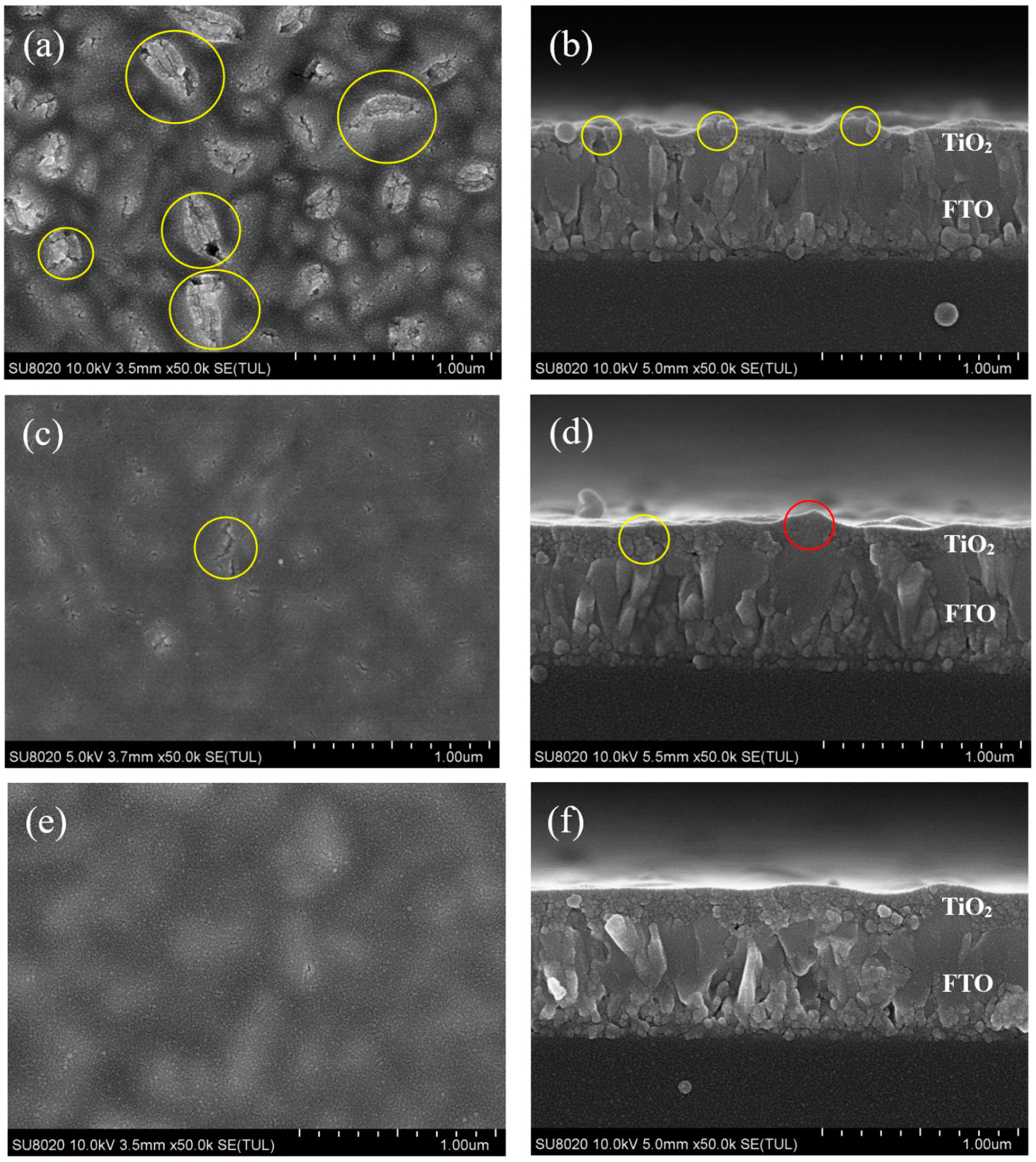
SEM images of TiO2 films with different numbers of spin-coating cycles are shown in Figure 3. Figure 3a,b respectively shows the top and cross-sectional views of TiO2 film with one spin-coating cycle. As shown in the figure, the film was undulating, and there were many cracks (as shown by the yellow circle in Figure 3a,b). The cracks are attributed to the rough surface of the FTO substrate. The TiO2 film generated large stress at the peaks of FTO, which could cause cracking during heating.
When TiO2 was spin-coated once, the thin film could not completely cover the peaks of FTO, as shown in Figure 3a,b. This will result in the FTO having direct contact with the perovskite layer, so the performance of solar cell devices may be poor.
Figure 3c,d are top-view images and cross-sectional images of two spin-coating cycles of TiO2, respectively. According to Figure 3c,d, the film was flatter than with one spin-coating cycle of TiO2, and there were few cracks in the film (as shown by the yellow circle in Figure 3c,d).
After spin-coating TiO2 twice, the FTO substrate was completely covered by the TiO2 film. Compared with one spin-coating cycle of TiO2 film, FTO peaks were basically not visible in the top view, which is also confirmed by the corresponding cross-sectional images shown in Figure 3c,d. The high FTO peak at the center of the cross-sectional image had also been covered by TiO2 (as shown by the red circle in Figure 3d). The TiO2 film could prevent contact between FTO and the perovskite layer, so it may improve the device performance.
Figure 3e,f are top-view and cross-sectional images of three spin-coating cycles of TiO2, respectively. As illustrated in Figure 3e,f, the film was thicker than with two spin-coating cycles of TiO2.
After spin-coating TiO2 three times, the film was very flat and smooth, with a thickness of about 200 nm, which contributed to the growth of perovskite film, as shown in Figure 3e,f. However, compared with two spin-coating cycles of TiO2 film, thicker TiO2 film made it less effective for electrons to be injected from the perovskite layer to the FTO substrate, which may deteriorate the performance of the device.
The schematic diagram extracted from the cross-sectional SEM images in Figure 3 is shown in Figure 4.
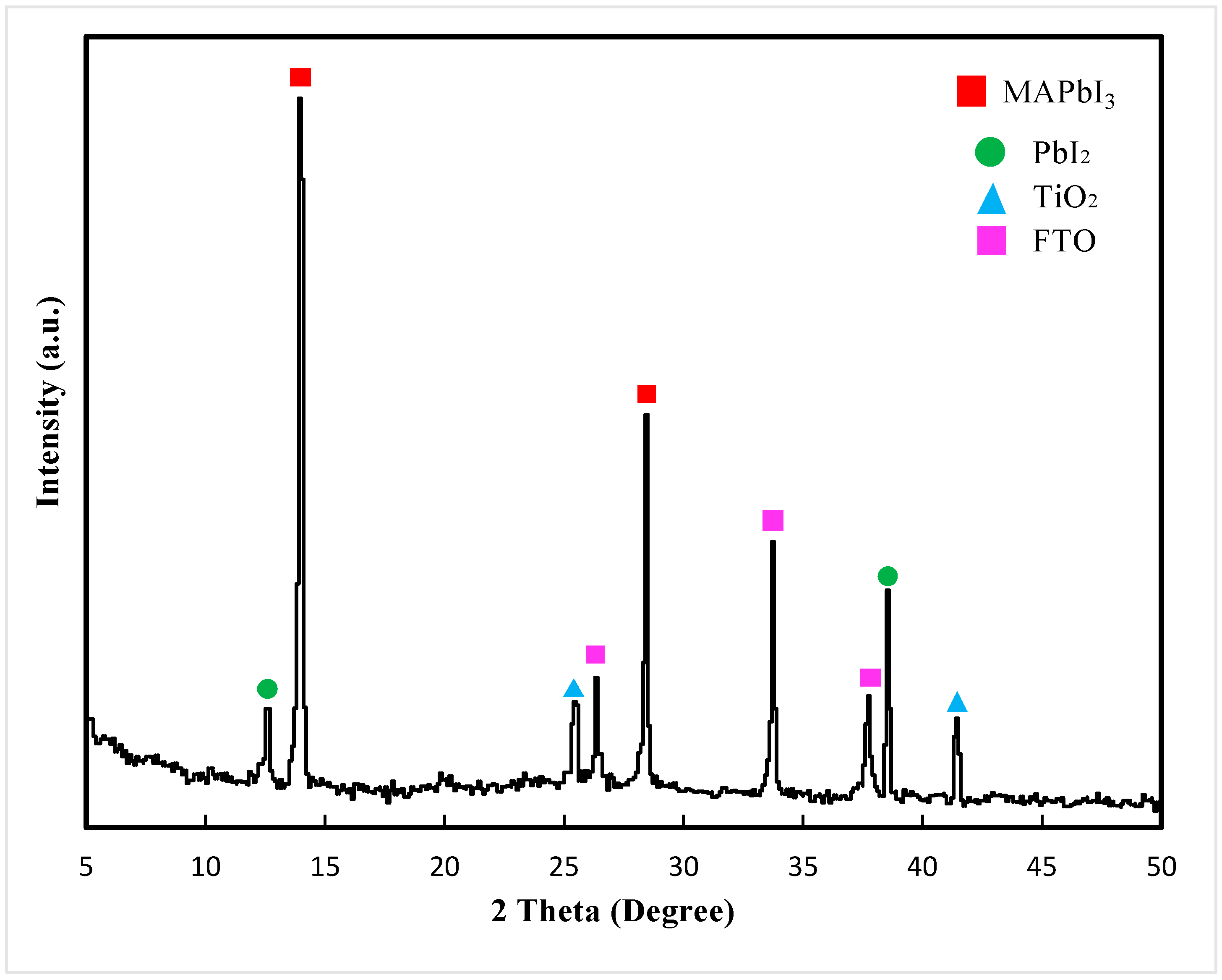
The XRD pattern of the perovskite light-absorbing layer film is shown in Figure 5. The characteristic diffraction peaks were located at 2θ = 14.19° and 28.50°, which corresponds to the (110) and (220) planes of the perovskite crystal planes [35,36], respectively. As shown in Figure 5, MAPbI3 had a tetragonal perovskite structure.
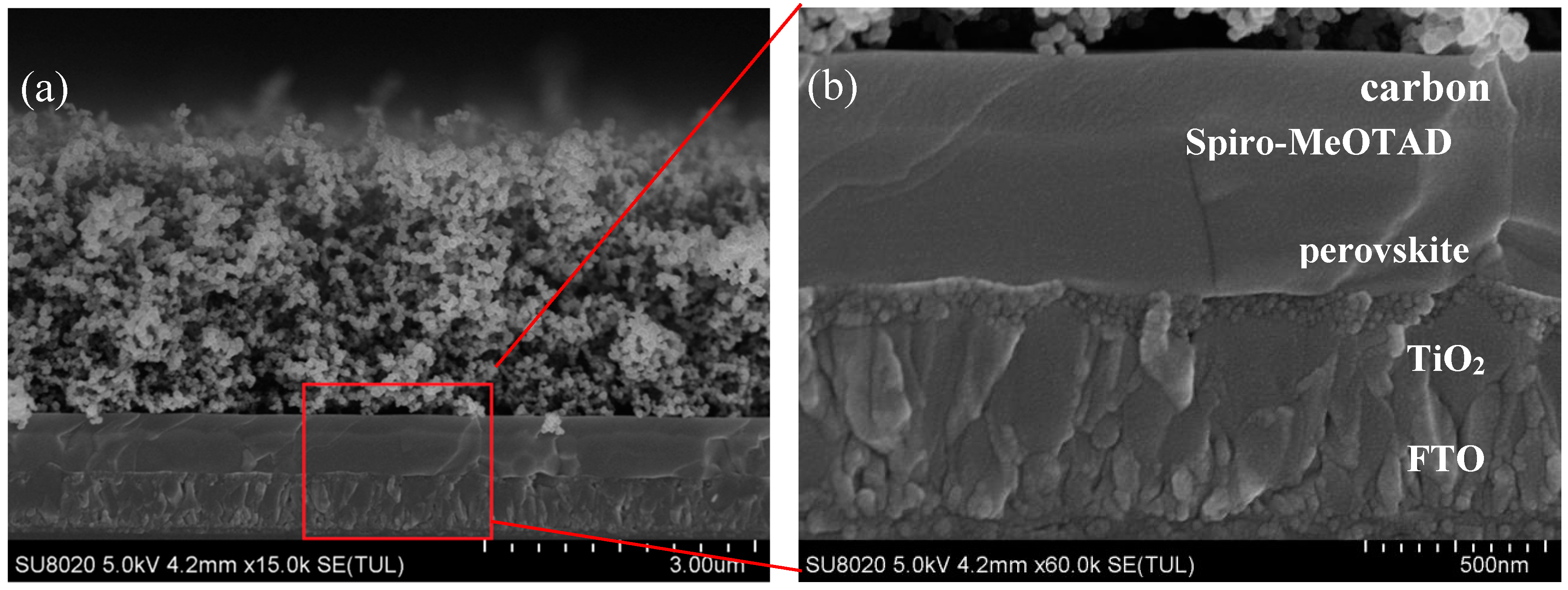
Cross-sectional SEM images of a perovskite solar cell with two cycles of spin-coated TiO2 are shown in Figure 6, where Figure 6b displays the magnified diagram of the marked area in the red rectangle in Figure 6a. The dense TiO2 layer was prepared by two spin-coating cycles. As shown in Figure 7, the TiO2 layer was dense and uniform; the grains of the perovskite layer were complete, with a thickness of about 400 nm; the thickness of the spiro-MeOTAD layer was about 250 nm; the top layer was a spongy-like carbon film with a thickness of about 3 μm.
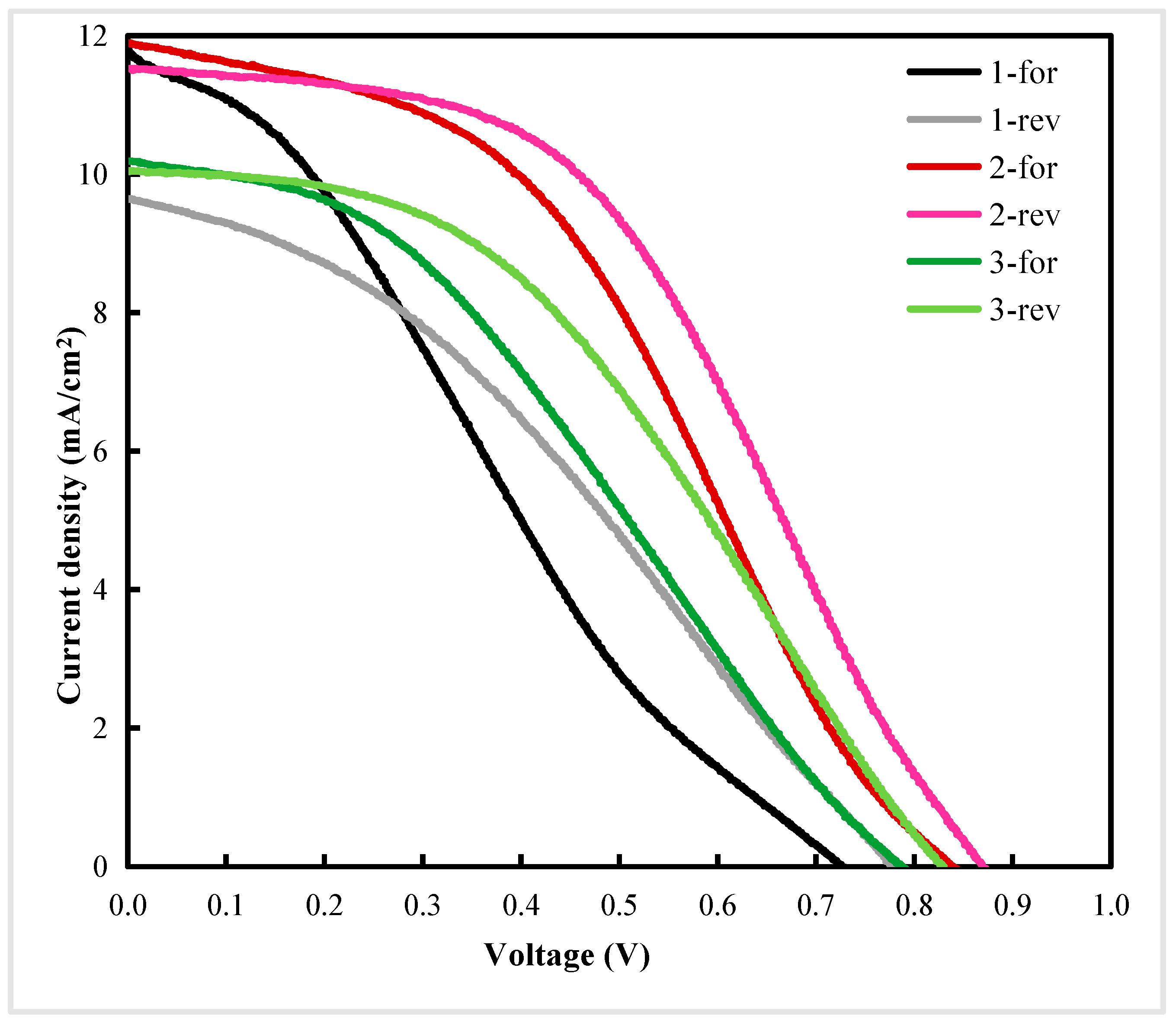
The J–V curves of PSCs with different spin-coating cycles are shown in Figure 7. As shown in Table 1, the performance parameters corresponded to the J–V curves in Figure 7. The series resistance and shunt resistance were calculated from the J–V curves. In this paper, -for and -rev represent forward-scanning and reverse-scanning, respectively. In Figure 7, 1-, 2-, and 3-represent the number of TiO2 spin-coating cycles. It can be seen from Table 1 that the performance of PSCs prepared with spin-coating for two cycles was better than others.
As shown in Table 1 and Figure 3a, compared with spin-coating for two cycles, when TiO2 films were fabricated using one spin-coating cycle, the films could not completely cover the peaks of FTO, and had pinholes. Therefore, the films may not be capable of passivating the defects efficiently. Any pinholes in the TiO2 film could lead to shunt pathways and direct contact between the CH3NH3PbI3 light-absorption layer and FTO, resulting in high leakage current and serious charge carrier recombination at the interface [18]. A device with an excessively thin TiO2 film could not completely cover the FTO, and would experience serious charge carrier recombination, contributing to low shunt resistance and leading to a low open-circuit voltage (Voc). As such, the performance of PSCs prepared with spin-coating for two cycles is better than spin-coating for one cycle.
When the number of spin-coating cycles was increased to three cycles, the thickness of TiO2 increased, as shown in Figure 3f. This led to poor transmittance and weaker light absorption of the perovskite film. When the thickness of TiO2 was increased, the distance became too large to transfer electrons from the perovskite film to the FTO. Therefore, the electrons run a longer distance. Furthermore, the excessively thick ETL had a higher series resistance, which contributed to low short-circuit photocurrent density (Jsc). Thus, the performance of PSCs prepared with spin-coating for two cycles was better than spin-coating for three cycles.

4. Conclusions

Using multiple-cycle spin-coated TiO2 films on rough FTO was demonstrated to reduce the effect of the rough FTO substrate and improve device performance for PSCs in this work.
It was found that the TiO2 ETL was optimized by using two spin-coating cycles. It could form a thin film without holes and cracks, avoiding contact between FTO and the perovskite layer to mitigate the recombination of electrons and holes and reduce energy loss at the interface. The solar cell device prepared with an optimized TiO2 layer had the best electrical performance, with small series resistance and large shunt resistance, so it could improve the performance of PSCs.
The influence of rough FTO on the TiO2 film can be reduced using this optimized method, meaning low-cost and low-quality FTO substrates can be used to fabricate solar cells or photodetectors.
However, there were still some points that need to be improved in our research; for example, an excessively high annealing temperature may degrade MAPbI3. An overly thick spiro-MeOTAD layer may also have some impact on the device, which was based on a carbon electrode in our work. Gold electrodes, the optimization of annealing temperature of MAPbI3, and spiro-MeOTAD layer thickness are currently under investigation.

Author Contributions

Conceptualization, X.Z. and D.C.; methodology, D.C.; formal analysis, J.C.; investigation, J.W., X.Z., J.Z., X.B., Y.Y., C.C., X.Y., B.L., Z.Z. and G.L.; resources, D.C.; data curation, D.C. and J.C.; writing—original draft preparation, J.W.; writing—review and editing, X.Y., B.L., Z.Z., G.L. and X.Z.; visualization, J.C.; supervision, X.Z.; funding acquisition, X.Z. All authors have read and agreed to the published version of the manuscript.

Funding

The authors gratefully acknowledge the Natural Science Foundation of China (no. 61875186), the Natural Science Foundation of Beijing (no. Z160002), the Key Research Projects of BISTU (2019KYNH227), and the Beijing Key Laboratory for Sensors of BISTU (no. 2019CGKF007).

Acknowledgments

Authors thank Yifei Wang, Xiaotong Li and Xiaolan Wang for helpful English grammar checking.

Conflicts of Interest

The authors declare no conflict of interest.

References

  1. Papež, N.; Skvarenina, L.; Tofel, P.; Sobola, D. Thermal stability of gallium arsenide solar cells. Photonics Prague 2017, 27, 1060313. [Google Scholar]
  2. Papež, N.; Gajdoš, A.; Dallaev, R.; Sobola, D.; Sedlak, P.; Motúz, R.; Nebojsa, A.; Grmela, L. Performance analysis of GaAs based solar cells under gamma irradiation. Appl. Surf. Sci. 2020, 510, 145329. [Google Scholar] [CrossRef]
  3. Snaith, H.J. Perovskites: The emergence of a new Era for low-cost, high-effificiency solar cells. J. Phys. Chem. Lett. 2013, 4, 3623–3630. [Google Scholar] [CrossRef]
  4. Green, M.A.; Ho-Baillie, A.; Snaith, H.J. The emergence of perovskite solar cells. Nat. Photonics 2014, 8, 506–514. [Google Scholar] [CrossRef]
  5. Yang, G.; Tao, H.; Qin, P.; Ke, W.; Fang, G. Recent progress in electron transport layers for efficient perovskite solar cells. J. Mater. Chem. 2016, 4, 3970–3990. [Google Scholar] [CrossRef]
  6. Green, M.A.; Ho-Baillie, A. Perovskite solar cells: The birth of a new era in photovoltaics. ACS Energy Lett. 2017, 2, 822–830. [Google Scholar] [CrossRef]
  7. Green, M.A.; Dunlop, E.D.; Levi, D.H.; Hohl-Ebinger, J.; Yoshita, M.; Ho-Baillie, A.W.Y. Solar cell efficiency tables (Version 55). Prog. Photovolt. 2020, 28, 3–15. [Google Scholar] [CrossRef]
  8. Eperon, C.E.; Burlakov, V.M.; Docampo, P.; Goriely, A.; Snaith, H.J. Morphological control for high performance, solution-processed planar heterojunction perovskite solar cells. Adv. Funct. Mater. 2014, 24, 151–157. [Google Scholar] [CrossRef]
  9. Liu, D.; Kelly, T.L. Perovskite solar cells with a planar heterojunction structure prepared using room-temperature solution processing techniques. Nat. Photonics 2014, 8, 133–138. [Google Scholar] [CrossRef]
  10. Zhou, H.; Chen, Q.; Li, G.; Luo, S.; Song, T.B.; Duan, H.S.; Hong, Z.; You, J.; Liu, Y.; Yang, Y. Interface engineering of highly efficient perovskite solar cells. Science 2014, 345, 542–546. [Google Scholar] [CrossRef]
  11. Ke, W.; Fang, G.; Liu, Q.; Xiong, L.; Qin, P.; Tao, H.; Wang, J.; Lei, H.; Li, B.; Wan, J.; et al. Low-temperature solution-processed tin oxide as an alternative electron transporting layer for efficient perovskite solar cells. J. Am. Chem. Soc. 2015, 137, 6730–6733. [Google Scholar] [CrossRef] [PubMed]
  12. Liu, Z.Y.; Sun, B.; Liu, X.Y.; Han, J.H.; Ye, H.B.; Tu, Y.X.; Chen, C.; Shi, T.L.; Lang, Z.R.; Liao, G.L. 15% effificient carbon based planar-heterojunction perovskite solar cells using TiO2/SnO2 bilayer as electron transport layer. J. Mater. Chem. A 2018, 6, 7409–7419. [Google Scholar] [CrossRef]
  13. Ren, Z.Q.; Wang, N.; Zhu, M.H.; Li, X.; Qi, J.Y. A NH4F interface passivation strategy to produce air-processed high-performance planar perovskite solar cells. Electrochim. Acta 2018, 282, 653–661. [Google Scholar] [CrossRef]
  14. Li, X.; Yang, J.Y.; Jiang, Q.H.; Lai, H.; Li, S.P.; Xin, J.W.; Chu, W.J.; Hou, J.D. Low-temperature solution-processed ZnSe electron transport layer for effificient planar perovskite solar cells with negligible hysteresis and improved photostability. ACS Nano 2018, 12, 5605–5614. [Google Scholar] [CrossRef] [PubMed]
  15. Ma, J.J.; Yang, G.; Qin, M.C.; Zheng, X.L.; Lei, H.W.; Chen, C.; Chen, Z.L.; Guo, Y.X.; Han, H.W.; Zhao, X.Z.; et al. MgO nanoparticle modifified anode for highly effificient SnO2-based planar perovskite solar cells. Adv. Sci. 2017, 4, 1700031. [Google Scholar] [CrossRef]
  16. Yu, X.; Zou, X.; Cheng, J.; Chen, D.; Yao, Y.; Chang, C.; Liu, B.; Wang, J.; Zhou, Z.; Li, G. Investigation on Low-temperature Annealing Process of Solution-processed TiO2 Electron Transport Layer for Flexible Perovskite Solar Cell. Materials 2020, 13, 1031. [Google Scholar] [CrossRef] [Green Version]
  17. Nwankwo, U.; Ngqoloda, S.; Nkele, A.C.; Arendse, C.J.; Ozoemena, K.I.; Ekwealor, A.B.C.; Jose, R.; Maaza, M.; Ezema, F.I. Effects of alkali and transition metal-doped TiO2 hole blocking layers on the perovskite solar cells obtained by a two-step sequential deposition method in air and under vacuum. RSC Adv. 2020, 10, 13139. [Google Scholar] [CrossRef] [Green Version]
  18. Supasai, T.; Henjongchom, N.; Tang, I.M.; Deng, F.; Rujisamphan, N. Compact nanostructured TiO2 deposited by aerosol spray pyrolysis for the hole-blocking layer in a CH3NH3PbI3 perovskite solar cell. Sol. Energy 2016, 136, 515–524. [Google Scholar] [CrossRef]
  19. Hu, H.; Dong, B.; Hu, H.; Chen, F.; Kong, M.; Zhang, Q.; Luo, T.; Zhao, L.; Guo, Z.; Li, J.; et al. Atomic layer deposition of TiO2 for high-efficiency hole-blocking layer in hole-conductor-free perovskite solar cells processed in ambient air. ACS Appl. Mater. Inter. 2016, 8, 17999–18007. [Google Scholar] [CrossRef]
  20. Ke, W.J.; Fang, G.J.; Wang, J.; Qin, P.L.; Tao, H.; Lei, H.W.; Liu, Q.; Dai, X.; Zhao, X.Z. Perovskite Solar Cell with an Efficient TiO2 Compact Film. ACS Appl. Mater. Inter. 2014, 6, 15959–15965. [Google Scholar] [CrossRef]
  21. Darvishzadeh, P.; Redzwan, G.; Ahmadi, R.; Gorji, N.E. Modeling the degradation/recovery of short-circuit current density in perovskite and thin film photovoltaics. Org. Electron. 2017, 43, 247–252. [Google Scholar] [CrossRef]
  22. Xiao, M.D.; Huang, F.Z.; Huang, W.C.; Dkhissi, Y.; Zhu, Y.; Etheridge, J.; Gray-Weale, A.; Bach, U.; Cheng, Y.B.; Spiccia, L. A fast deposition-crystallization procedure for highly efficient lead iodide perovskite thin-film solar cells. Angew. Chem. 2014, 126, 10056–10061. [Google Scholar] [CrossRef]
  23. Ahn, N.; Son, D.Y.; Jang, I.H.; Kang, S.M.; Choi, M.; Park, N.G. Highly reproducible perovskite solar cells with average efficiency of 18.3% and best efficiency of 19.7% fabricated via lewis base adduct of lead (II) iodide. J. Am. Chem. Soc. 2015, 137, 8696–8699. [Google Scholar] [CrossRef] [PubMed]
  24. Ke, W.; Zhao, D.; Cimaroli, A.J.; Grice, C.R.; Qin, P.; Liu, Q.; Xiong, L.; Yan, Y.; Fang, G. Effects of annealing temperature of tin oxide electron selective layers on the performance of perovskite solar cells. J. Mater. Chem. A 2015, 3, 24163. [Google Scholar] [CrossRef]
  25. Dao, V.D.; Larina, L.L.; Choi, H.S. Minimizing energy losses in perovskite solar cells using plasma-treated transparent conducting layers. Thin Solid Films 2015, 593, 10–16. [Google Scholar] [CrossRef]
  26. Song, S.; Moon, B.J.; Hörantner, M.T.; Lim, J.; Kang, G.; Park, M.; Kim, J.Y.; Snaith, H.J.; Park, T. Interfacial Electron Accumulation for Efficient Homo-Junction Perovskite Solar Cells. Nano Energy 2016, 28, 269. [Google Scholar] [CrossRef]
  27. Baek, S.; Han, J.W.; Vidyasagar, D.; Cho, H.; HA, H.H.; Kim, D.H.; Heo, Y.W.; Lee, S. Room-Temperature-Processed Amorphous Sn-In-O Electron Transport Layer for Perovskite Solar Cells. Materials 2020, 13, 32. [Google Scholar] [CrossRef] [Green Version]
  28. Zuo, L.J.; Gu, Z.W.; Ye, T.; Fu, W.F.; Wu, G.; Li, H.Y.; Chen, H.Z. Enhanced Photovoltaic Performance of CH3NH3PbI3 Perovskite Solar Cells through Interfacial Engineering Using Self-Assembling Monolayer. J. Am. Chem. Soc. 2015, 137, 2674–2679. [Google Scholar] [CrossRef]
  29. Lai, W.C.; Lin, K.W.; Guo, T.F.; Chen, P.; Wang, Y.T. Conversion efficiency improvement of inverted ch3nh3pbi3 perovskite solar cells with room temperature sputtered zno by adding the c60. Appl. Phys. Lett. 2015, 107, 253301. [Google Scholar] [CrossRef] [Green Version]
  30. Ren, X.D.; Yang, D.; Yang, Z.; Feng, J.S.; Zhu, X.J.; Niu, J.Z.; Liu, Y.C.; Zhao, W.G.; Liu, S.F. Solution-Processed Nb:SnO2 Electron Transport Layer for Efficient Planar Perovskite Solar Cells. ACS Appl. Mater. Inter. 2017, 9, 2421–2429. [Google Scholar] [CrossRef]
  31. Ren, H.Y.; Zou, X.P.; Cheng, J.; Ling, T.; Bai, X.; Chen, D. Facile Solution Spin-Coating SnO2 Thin Film Covering Cracks of TiO2 Hole Blocking Layer for Perovskite Solar Cells. Coatings 2018, 8, 314. [Google Scholar] [CrossRef] [Green Version]
  32. Malviya, K.D.; Dotan, H.; Yoon, K.R.; Kim, I.D.; Rothschild, A. Rigorous substrate cleaning process for reproducible thin film hematite (alpha-Fe2O3) photoanodes. J. Mater. Res. 2016, 31, 1565–1573. [Google Scholar] [CrossRef] [Green Version]
  33. Im, J.H.; Jang, I.H.; Pellet, N.; Gratzel, M.; Park, N.G. Growth of CH3NH3PbI3 Cuboids with Controlled Size for High-Efficiency Perovskite Solar Cells. Nat. Nanotechnol. 2014, 9, 927–932. [Google Scholar] [CrossRef]
  34. Zhang, N.; Guo, Y.; Yin, X.; He, M.; Zou, X. Spongy carbon film deposited on a separated substrate as counter electrode for perovskite-based solar cell. Mater. Lett. 2016, 182, 248–252. [Google Scholar] [CrossRef]
  35. Mohammadpour, F.; Altomare, M.; So, S.; Lee, K.; Schmuki, P. High-temperature annealing of TiO2 nanotube membranes for efficient dye-sensitized solar cells. Semicond. Sci. Technol. 2016, 31, 014010. [Google Scholar] [CrossRef] [Green Version]
  36. Cao, D.H.; Stoumpos, C.C.; Malliakas, C.D.; Katz, M.J.; Farha, O.K.; Hupp, J.T.; Kanatzidis, M.G. Remnant PbI2, an unforeseen necessity in high-efficiency hybrid perovskite-based solar cells? APL Mater. 2014, 2, 091101. [Google Scholar] [CrossRef] [Green Version]
Figure 1. Flow schematic of device fabrication.
Materials 13 02272 g001
Figure 2. SEM images of top view (a), cross section (b), and schematic diagram (c) of the rough surface of the FTO substrate.
Materials 13 02272 g002
Figure 3. SEM images of TiO2 film with different spin-coating cycles: (a,c,e) Top view images of TiO2 for one, two, and three spin-coating cycles, respectively; (b,d,f) Cross-sectional view images of TiO2 for one, two, and three spin-coating cycles, respectively.
Materials 13 02272 g003
Figure 4. Schematic diagram of multiple layers of TiO2 on rough FTO substrate. (a): rough FTO; (b): 1 layer of TiO2 on the FTO; (c): 2 layer of TiO2 on the FTO; (d): 3 layer of TiO2 on the FTO.
Materials 13 02272 g004
Figure 5. XRD pattern of perovskite light-absorbing layer film.
Materials 13 02272 g005
Figure 6. (a) Cross-sectional SEM images of perovskite solar cell with two cycles of spin-coating TiO2; (b) An enlargement of the red frame in (a).
Materials 13 02272 g006
Figure 7. Current–voltage (J–V) curves of perovskite solar cells with different spin-coating cycles.
Materials 13 02272 g007
Table 1. Performance parameters of perovskite solar cells with different spin-coating cycles of TiO2.
SamplePCE a (%)Voc b (V)Jsc c (mA/cm2)FF dRs e (Ωcm2)Rsh f (Ωcm2)Average Thickness g (nm)Standard Error of Thickness (nm)RMS h (nm)Standard Error of Roughness (nm)
1-for2.260.7311.810.2639.88159.591011.64321.72
1-rev2.590.789.650.3453.15268.20
2-for4.140.8411.900.4233.15322.821501.77191.20
2-rev4.680.8711.530.4732.801026.60
3-for2.870.7910.190.3648.42378.791892.45160.97
3-rev3.510.8310.050.4245.601637.45
Notes: a PCE: power conversion efficiency; b Voc: open-circuit voltage; c Jsc: short-circuit photocurrent density; d FF: fill factor; e Rs: series resistance; f Rsh: shunt resistance; g Average thickness: the average thickness of TiO2 films; h RMS: roughness measurement of the surface of TiO2 films.