Selective Laser Sintering (SLS) and Post-Processing of Prosopis Chilensis/Polyethersulfone Composite (PCPC)

 ,
,
Abstract
:1. Introduction
2. Materials and Method
2.1. Materials
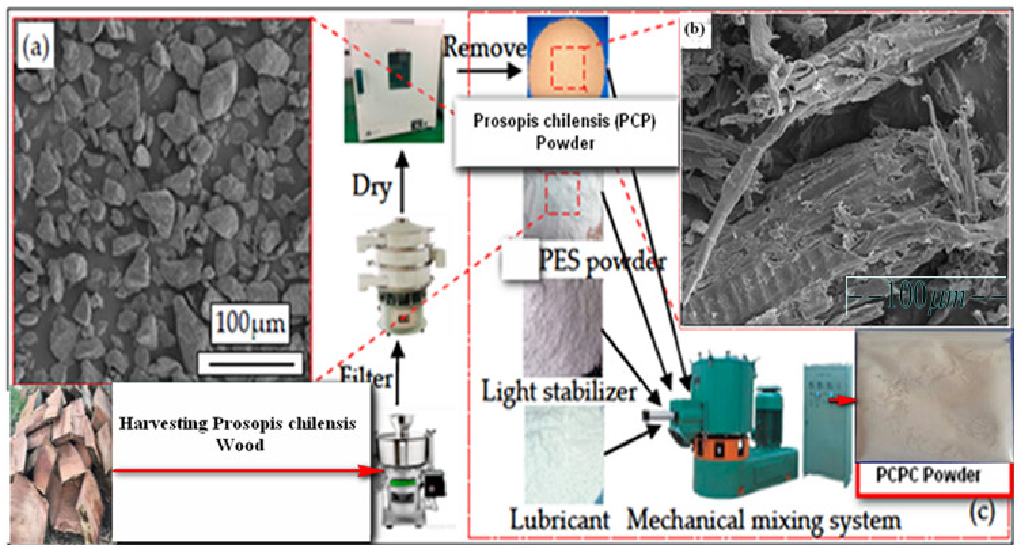
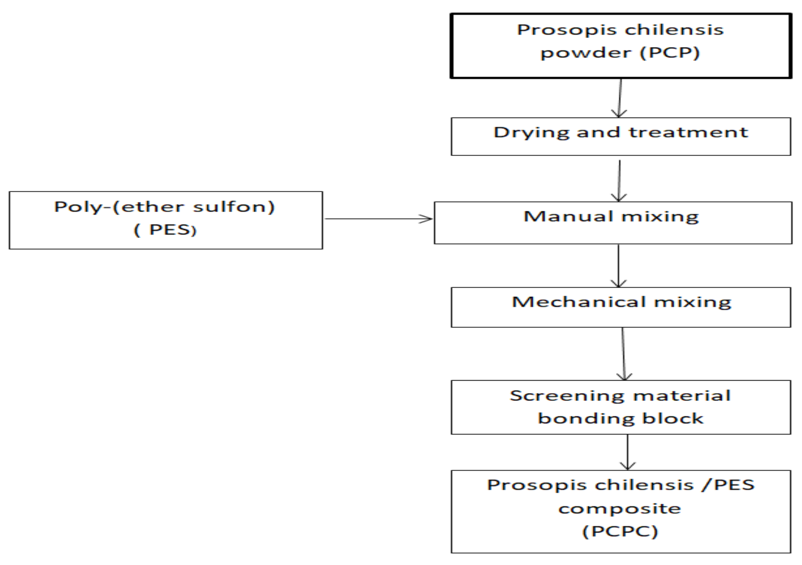
2.1.1. PCP
2.1.2. Prosopis Chilensis/PES Composite Powder (PCPC)
2.2. Methodology
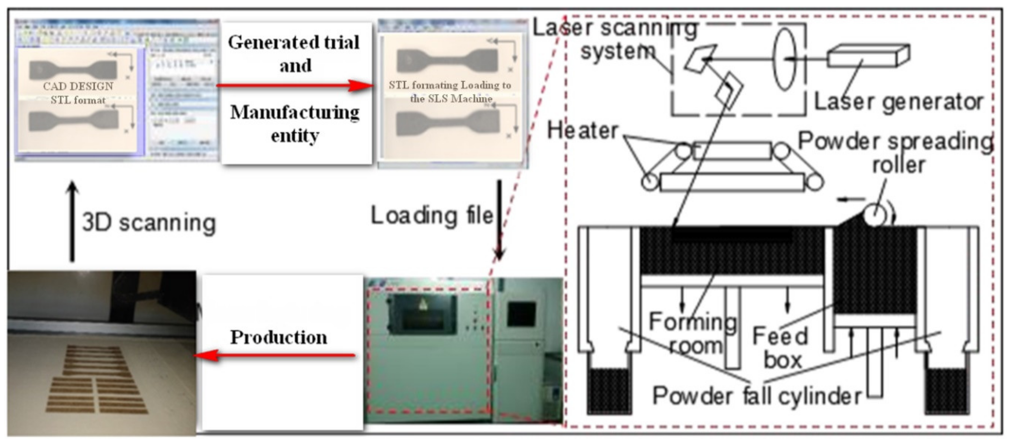
2.2.1. Selective Laser Sintering
2.2.2. Post-Processing
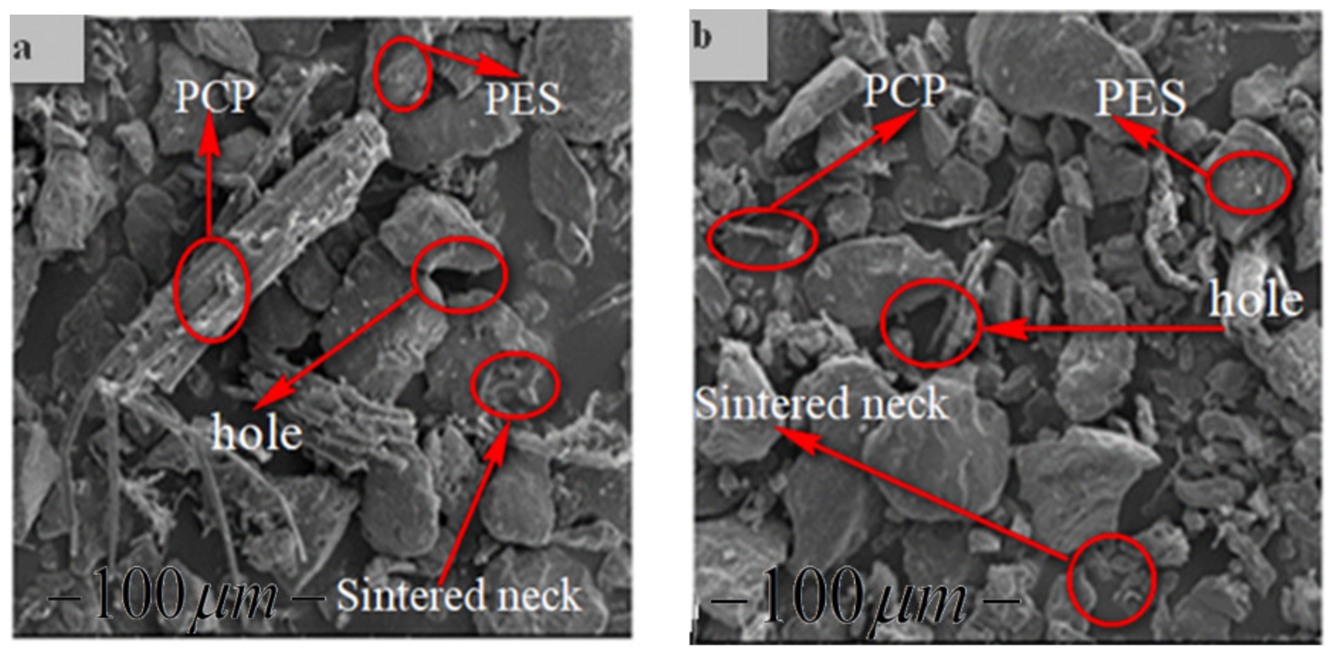
2.2.3. Scanning Electron Microscopy (SEM)
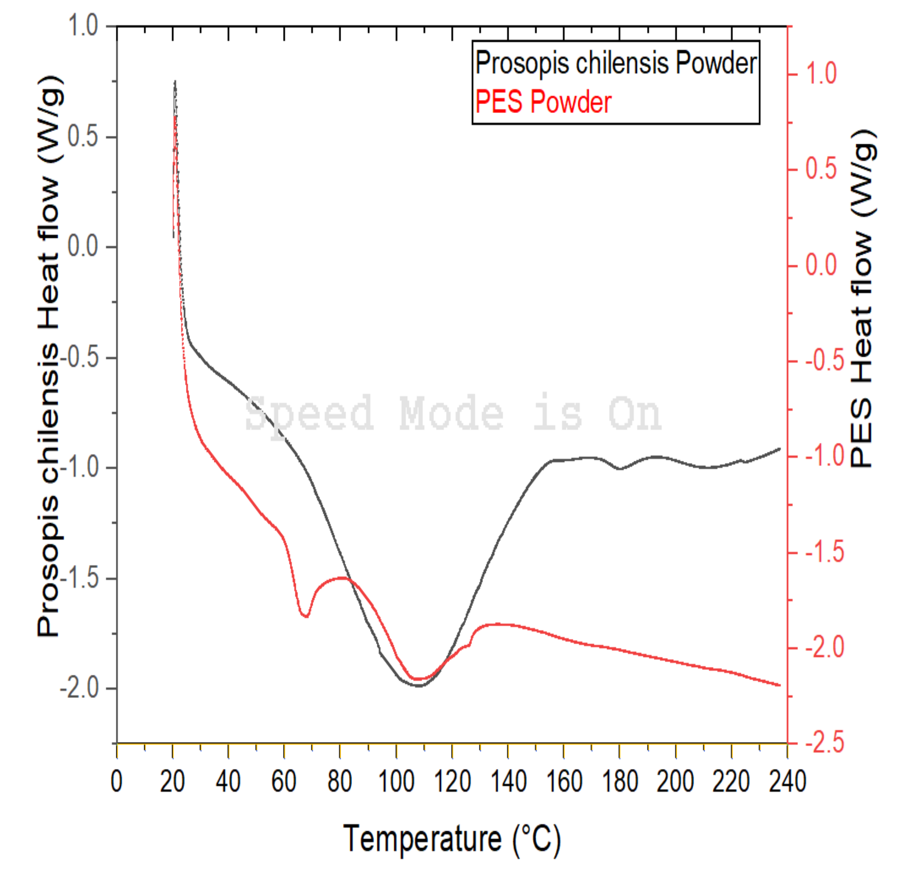
2.2.4. Differential Scanning Calorimetry
2.2.5. Mechanical Testing
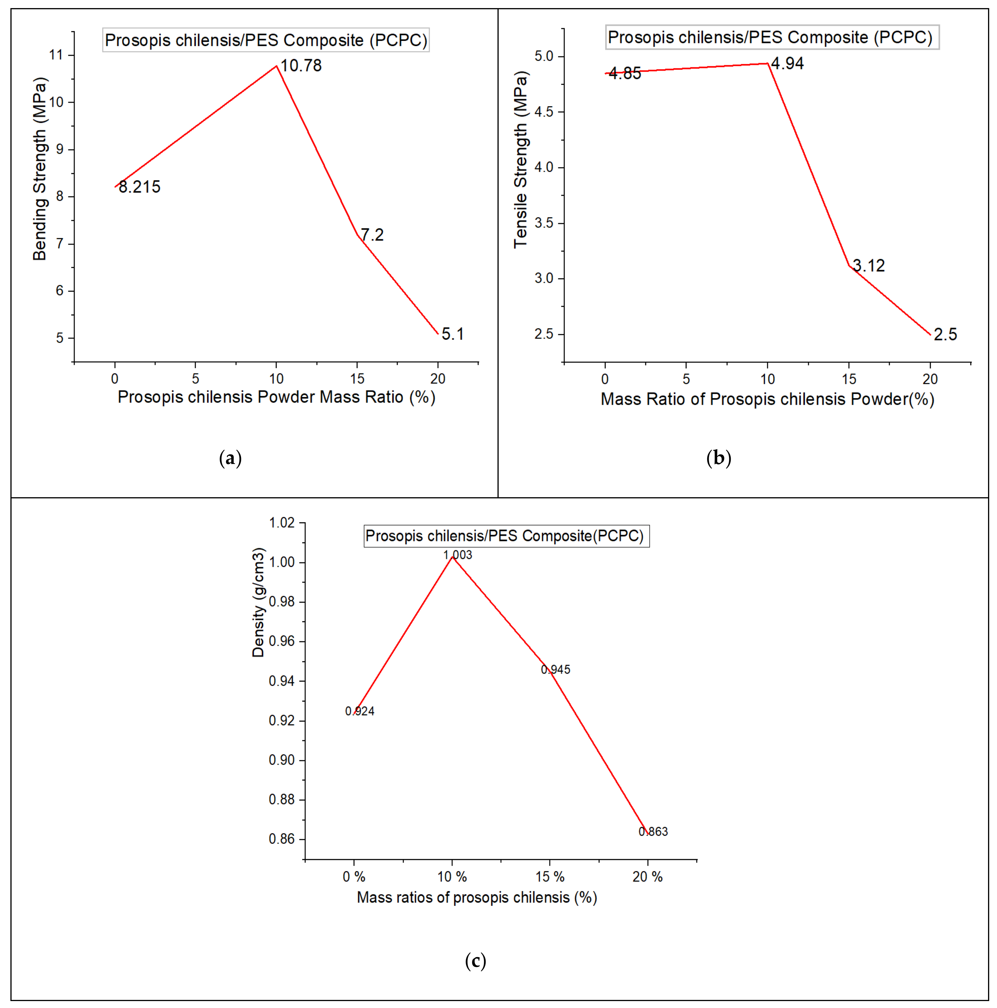
2.2.6. Density
2.2.7. Dimensional Precision (DP)
3. Results and Discussion
3.1. Single-Layer Sintering
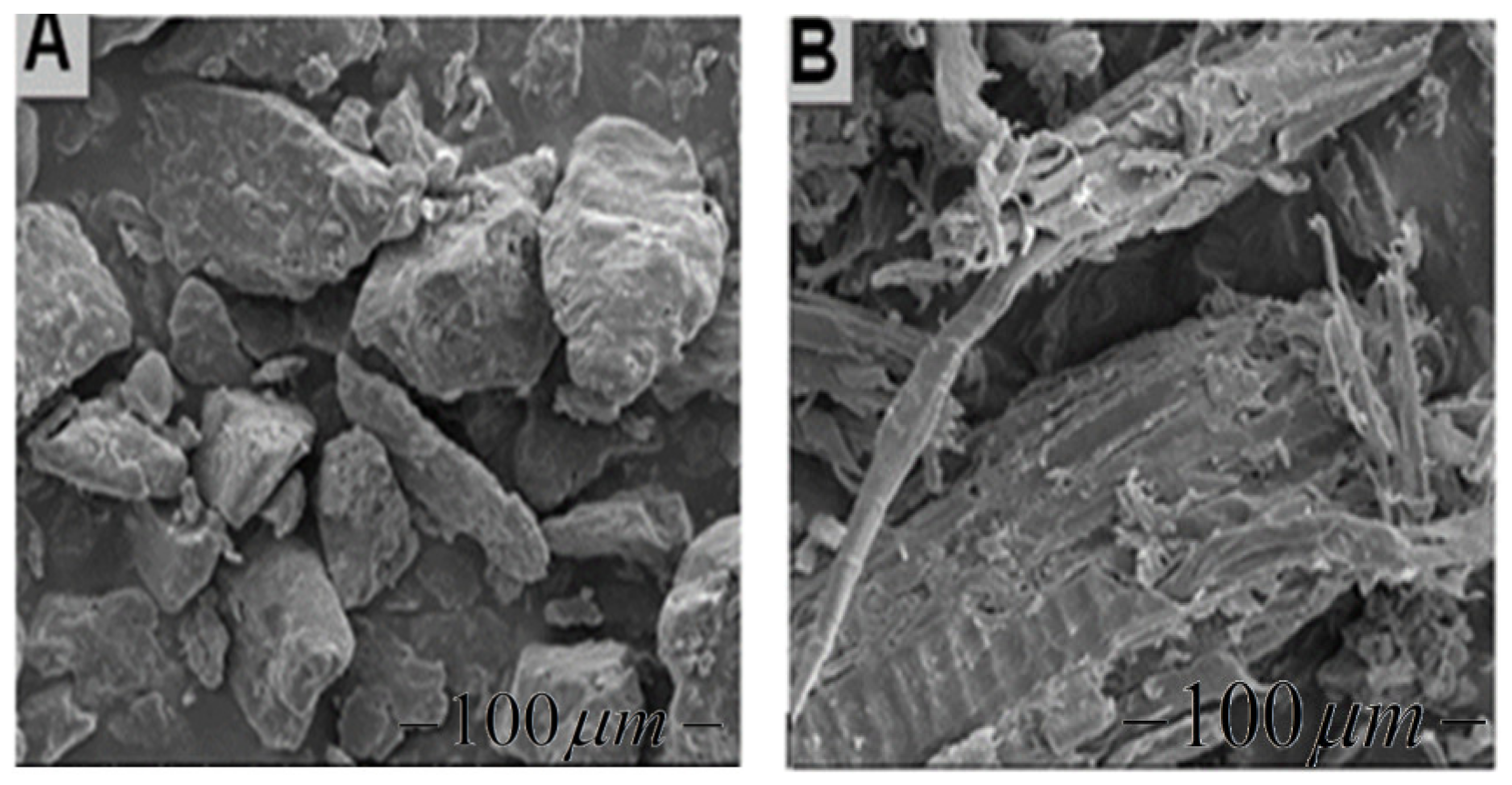
3.2. PCPC Morphology
3.3. Selective Laser Sintering Experiment
3.4. Mechanical Properties
3.5. The Surface Quality of the Sintered Part
3.6. Sintering Temperature of the PCPC
4. Conclusions
Author Contributions
Funding
Acknowledgments
Conflicts of Interest
References
- Beaman, J.J.; Barlow, J.W.; Bourell, D.L.; Crawford, R.H.; Marcus, H.L.; McAlea, K.P. Solid Freeform Fabrication: A New Direction in Manufacturing; Kluwer Academic Publishers: Norwell, MA, USA, 1997; Volume 2061, pp. 25–49. [Google Scholar]
- Guo, Y.; Jiang, K.; Bourell, D.L. Accuracy and mechanical property analysis of LPA12 parts fabricated by laser sintering. Polym. Test. 2015, 42, 175–180. [Google Scholar] [CrossRef]
- Yuan, S.; Bai, J.; Chua, C.K.; Wei, J.; Zhou, K. Material evaluation and process optimization of CNT-coated polymer powders for selective laser sintering. Polymers 2016, 8, 370. [Google Scholar] [CrossRef] [PubMed] [Green Version]
- Guo, Y.; Jiang, K.; Bourell, D.L. Preparation and laser sintering of limestone PA 12 composite. Polym. Test. 2014, 37, 210–215. [Google Scholar] [CrossRef]
- Gibbons, G.J.; Williams, R.; Purnell, P.; Farahi, E. 3D Printing of cement composites. Adv. Appl. Ceram. 2010, 109, 287–290. [Google Scholar] [CrossRef] [Green Version]
- Yu, Y.; Guo, Y.; Jiang, T.; Li, J.; Jiang, K.; Zhang, H. Study on Process and Parameter Optimization of Selective Laser Sintering of Walnut Shell Composite Powder. BioResources 2018, 13, 3017–3029. [Google Scholar] [CrossRef]
- Zeng, W.; Guo, Y.; Jiang, K.; Yu, Z.; Liu, Y. Preparation and Selective Laser Sintering Of Rice Husk-Plastic Composite Powder and Post Processing. Dig. J. Nanomater. Biostruct. 2012, 7, 1063–1070. [Google Scholar]
- Li, J.; Idriss, A.I.I.; Guo, Y.; Wang, Y.; Zhang, Z.; Zhang, H.; Elfaki, E.A. Selective Laser Sintering and Post-Processing of Sisal Fiber/Poly-(ether sulfone) Composite Powder. BioResources 2020, 15, 1338–1353. [Google Scholar]
- Bai, J.; Zhang, B.; Song, J.; Bi, G.; Wang, P.; Wei, J. The effect of processing conditions on the mechanical properties of polyethylene produced by selective laser sintering. Polym. Test. 2016, 52, 89–93. [Google Scholar] [CrossRef]
- Lu, K.; Reynolds, W.T. 3DP process for fine mesh structure printing. Powder Technol. 2008, 187, 11–18. [Google Scholar] [CrossRef]
- Qi, F.; Chen, N.; Wang, Q. Preparation of PA11/BaTiO3 nanocomposite powders with improved processability, dielectric and piezoelectric properties for use in selective laser sintering. Mater. Des. 2017, 131, 135–143. [Google Scholar] [CrossRef]
- Guo, H.; Chen, Y.; Chen, X.; Wen, R.; Yue, G.H.; Peng, D.L. Facile synthesis of near-monodisperse Ag@ Ni core–shell nanoparticles and their application for catalytic generation of hydrogen. Nanotechnology 2011, 22, 195604. [Google Scholar] [CrossRef]
- Yu, Y.; Guo, Y.; Jiang, T.; Jiang, K.; Li, J.; Guo, S. Laser sintering and post-processing of a walnut shell/Co-PES composite. Rsc Adv. 2017, 7, 23176–23181. [Google Scholar] [CrossRef] [Green Version]
- Saboori, A.; Gallo, D.; Biamino, S.; Fino, P.; Lombardi, M. An overview of additive manufacturing of titanium components by directed energy deposition: Microstructure and mechanical properties. Appl. Sci. 2017, 7, 883. [Google Scholar] [CrossRef] [Green Version]
- Aldahash, S.A. Optimum manufacturing parameters in selective laser sintering of PA12 with white cement additives. Int. J. Adv. Manuf. Technol. 2018, 96, 257–270. [Google Scholar] [CrossRef]
- Tiwari, S.K.; Pande, S.; Bobade, S.M.; Kumar, S. Assessment of mechanical properties and flammability of magnesium oxide/PA12 composite material for SLS process. Rapid Prototyp. J. 2019, 25, 176–186. [Google Scholar] [CrossRef]
- Leach, R.K.; Bourell, D.; Carmignato, S.; Donmez, A.; Senin, N.; Dewulf, W. Geometrical metrology for metal additive manufacturing. CIRP Ann. 2019, 68, 677–700. [Google Scholar] [CrossRef]
- Sofia, D.; Barletta, D.; Poletto, M. Laser sintering process of ceramic powders: The effect of particle size on the mechanical properties of sintered layers. Addit. Manuf. 2018, 23, 215–224. [Google Scholar] [CrossRef]
- Sun, Z.; Yang, L.; Zhang, D.; Song, W. High performance, flexible and renewable nano-biocomposite artificial muscle based on mesoporous cellulose/ionic liquid electrolyte membrane. Sens. Actuators B Chem. 2019, 283, 579–589. [Google Scholar] [CrossRef]
- Sun, Z.; Yang, L.; Zhang, D.; Bian, F.; Song, W. High-Performance biocompatible nano-biocomposite artificial muscles based on a renewable ionic electrolyte made of cellulose dissolved in ionic liquid. Nanotechnology 2019, 30, 285503. [Google Scholar] [CrossRef]
- Sofia, D.; Chirone, R.; Lettieri, P.; Barletta, D.; Poletto, M. Selective laser sintering of ceramic powders with bimodal particle size distribution. Chem. Eng. Res. Design 2018, 136, 536–547. [Google Scholar] [CrossRef] [Green Version]
- Sofia, D.; Granese, M.; Barletta, D.; Poletto, M. Laser sintering of unimodal distributed glass powders of different size. Procedia Eng. 2015, 102, 749–758. [Google Scholar] [CrossRef] [Green Version]
- Sun, Z.; Du, S.; Zhang, D.; Song, W. Influence of pH and loading of PANI on electrochemical and electromechanical properties for high-performance renewable soft actuator with nano-biocomposite electrode. React. Funct. Polym. 2019, 139, 102–111. [Google Scholar] [CrossRef]
- Sun, Z.; Song, W.; Zhao, G.; Wang, H. Chitosan-Based polymer gel paper actuators coated with multi-wall carbon nanotubes and MnO2 composite electrode. Cellulose 2017, 24, 4383–4392. [Google Scholar] [CrossRef]
- Idriss, A.I.; Li, J.; Wang, Y.; Guo, Y.; Elfaki, E.A. Effects of Various Processing Parameters on the Mechanical Properties of Sisal fiber/PES Composites Produced via Selective Laser Sintering. BioResources 2020, 15, 5710–5724. [Google Scholar]


| PCP/PES Ratios | Density (g cm3) | Dimensional Accuracy of the PCPC Parts (%) | ||
|---|---|---|---|---|
| X | Y | Z | ||
| Pure PES | 0.924 | 99.88 | 99.42 | 91.015 |
| PCPC (10/90) | 1.003 | 99.937 | 99.572 | 92.024 |
| PCPC (15/85) | 0.945 | 99.883 | 99.40 | 90.703 |
| PCPC (20/80) | 0.863 | 99.862 | 99.380 | 88.495 |
| Material | Tensile Strength (MPa) | Bending Strength (MPa) | Reference |
|---|---|---|---|
| Prosopis chilensis/PES (20/80 wt/wt) | 2.50 | 5.10 | Current study |
| Wood/plastic | 2.17 | 3.22 | Guo et al. 2011 [12] |
| Walnut shell/co-PES (20/80 wt/wt) | 2.3 | 4.2 | Yueqiang et al. 2017 [13] |
| Sisal fiber/PES (SFPC) (20/80 wt/wt) | 3.24 | 7.12 | Li Jian et al. 2020 [8] |
© 2020 by the authors. Licensee MDPI, Basel, Switzerland. This article is an open access article distributed under the terms and conditions of the Creative Commons Attribution (CC BY) license (http://creativecommons.org/licenses/by/4.0/).
Share and Cite
Idriss, A.I.B.; Li, J.; Wang, Y.; Guo, Y.; Elfaki, E.A.; Adam, S.A. Selective Laser Sintering (SLS) and Post-Processing of Prosopis Chilensis/Polyethersulfone Composite (PCPC). Materials 2020, 13, 3034. https://doi.org/10.3390/ma13133034
Idriss AIB, Li J, Wang Y, Guo Y, Elfaki EA, Adam SA. Selective Laser Sintering (SLS) and Post-Processing of Prosopis Chilensis/Polyethersulfone Composite (PCPC). Materials. 2020; 13(13):3034. https://doi.org/10.3390/ma13133034
Chicago/Turabian StyleIdriss, Aboubaker I. B., Jian Li, Yangwei Wang, Yanling Guo, Elkhawad A. Elfaki, and Shareef A. Adam. 2020. "Selective Laser Sintering (SLS) and Post-Processing of Prosopis Chilensis/Polyethersulfone Composite (PCPC)" Materials 13, no. 13: 3034. https://doi.org/10.3390/ma13133034