Wear Resistance Enhancement of Al6061 Alloy Surface Layer by Laser Dispersed Carbide Powders


Abstract
:
1. Introduction
2. Materials and Methods
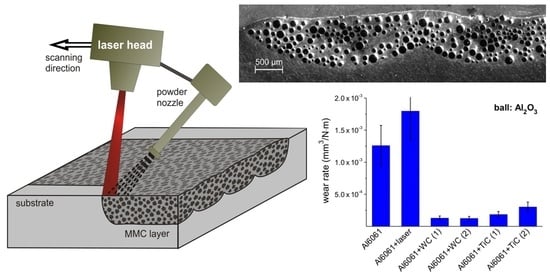
2.1. Laser Stand
2.2. Substrate Material and Reinforcing Powders
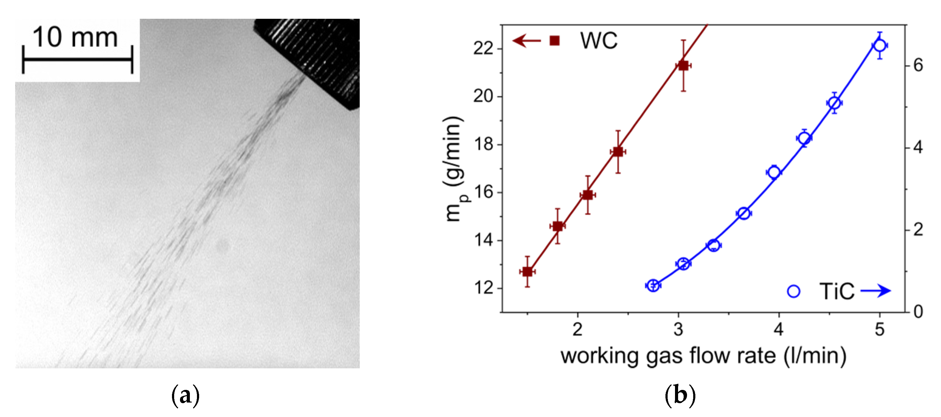
2.3. Powder Feeding
2.4. Selection of Process Parameters
3. Results and Discussion
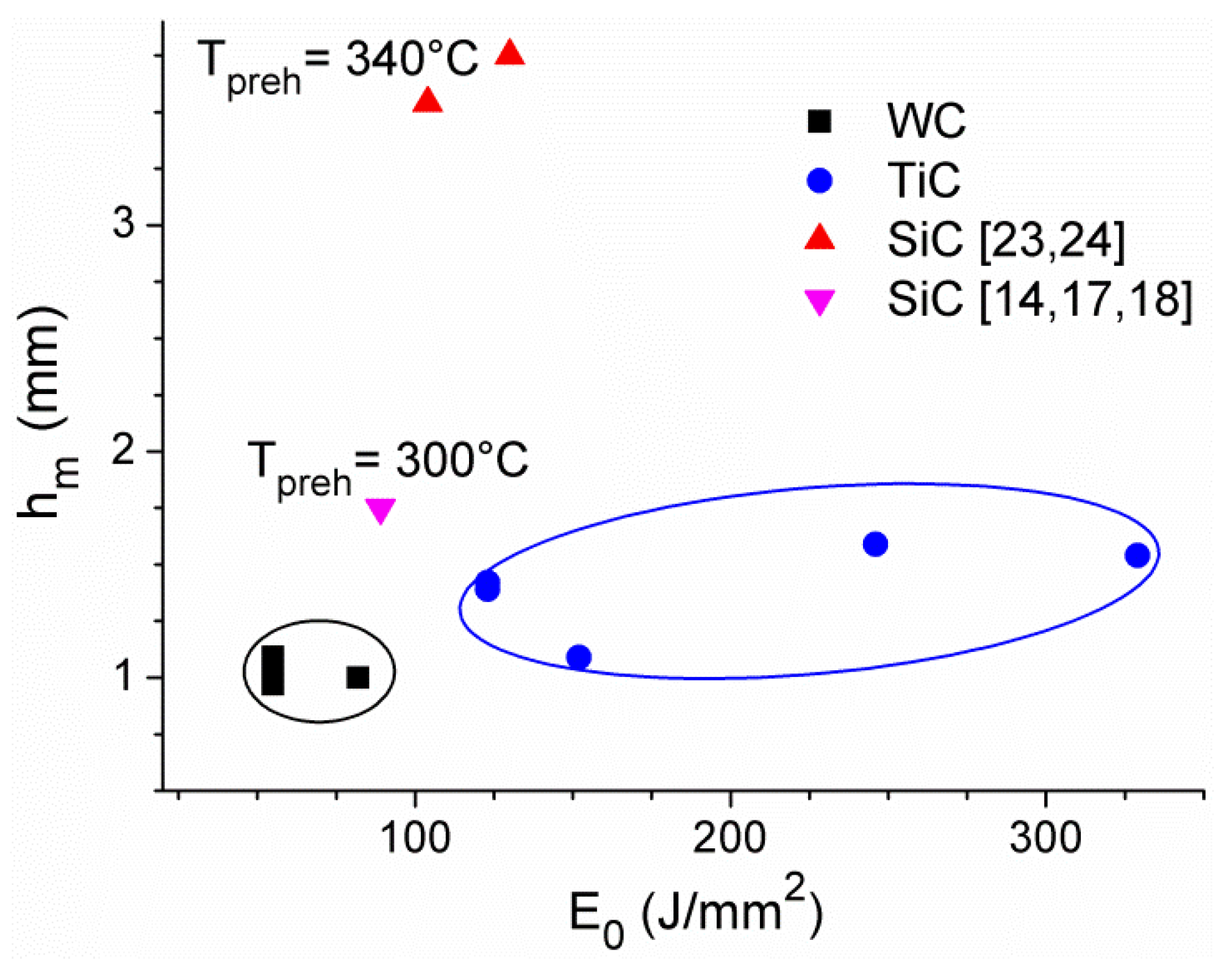
3.1. Single Track MMC Layers
3.2. Multi-Track Reinforced MMC Coatings
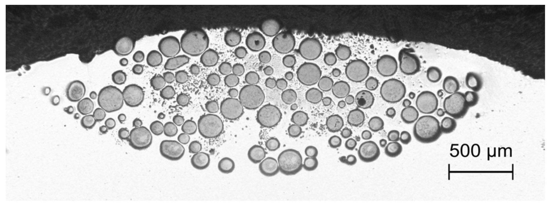
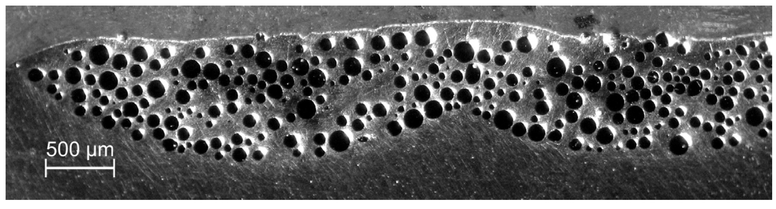
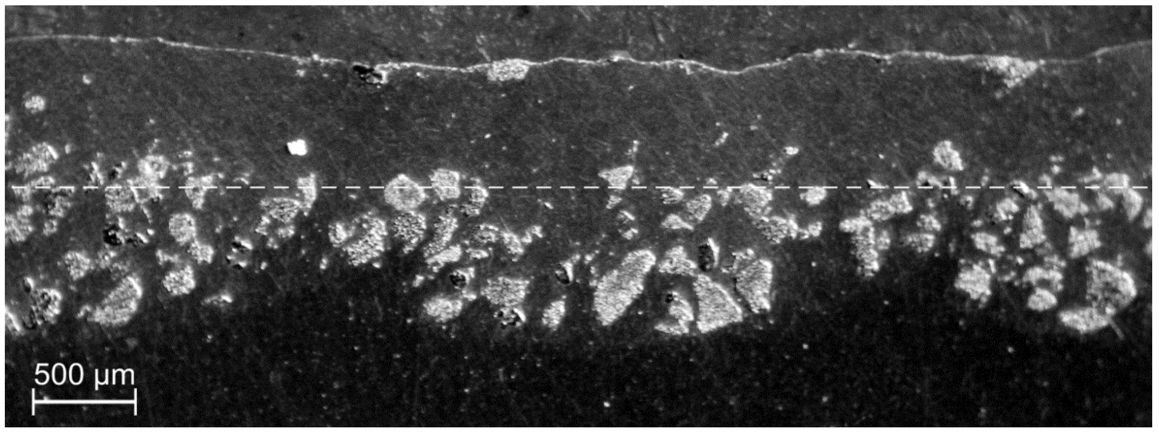
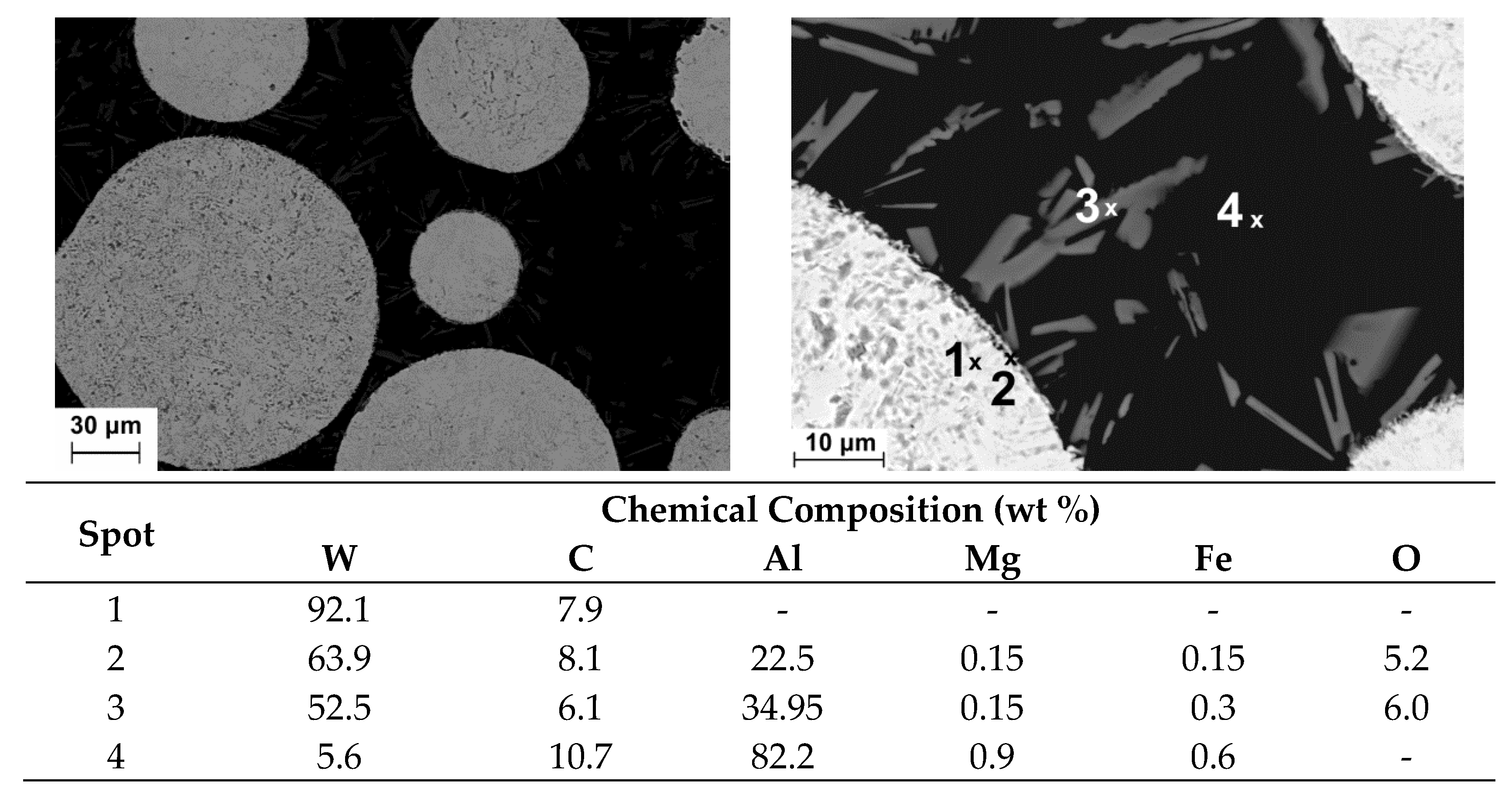
3.3. MMC Morfology and Chemical Composition
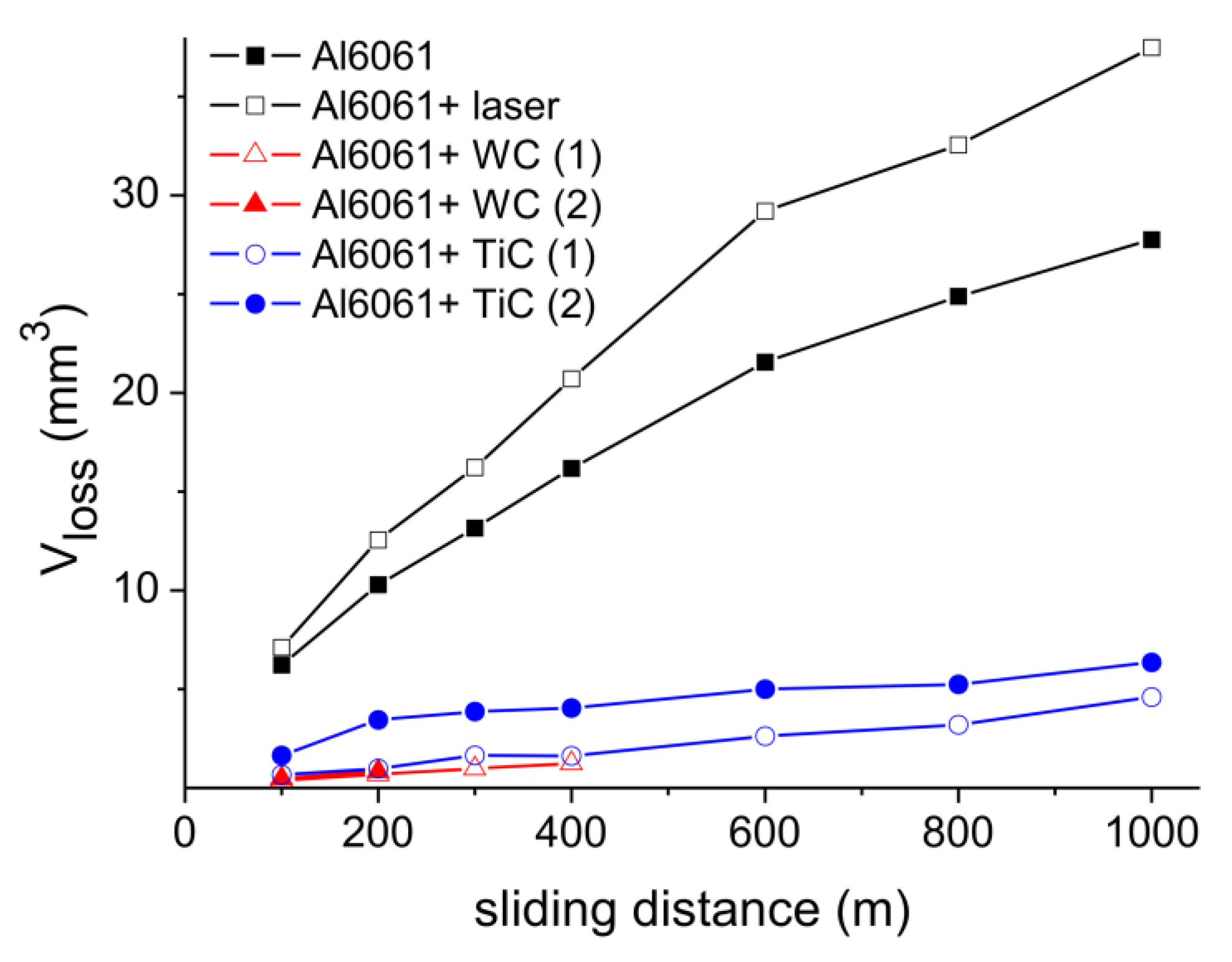
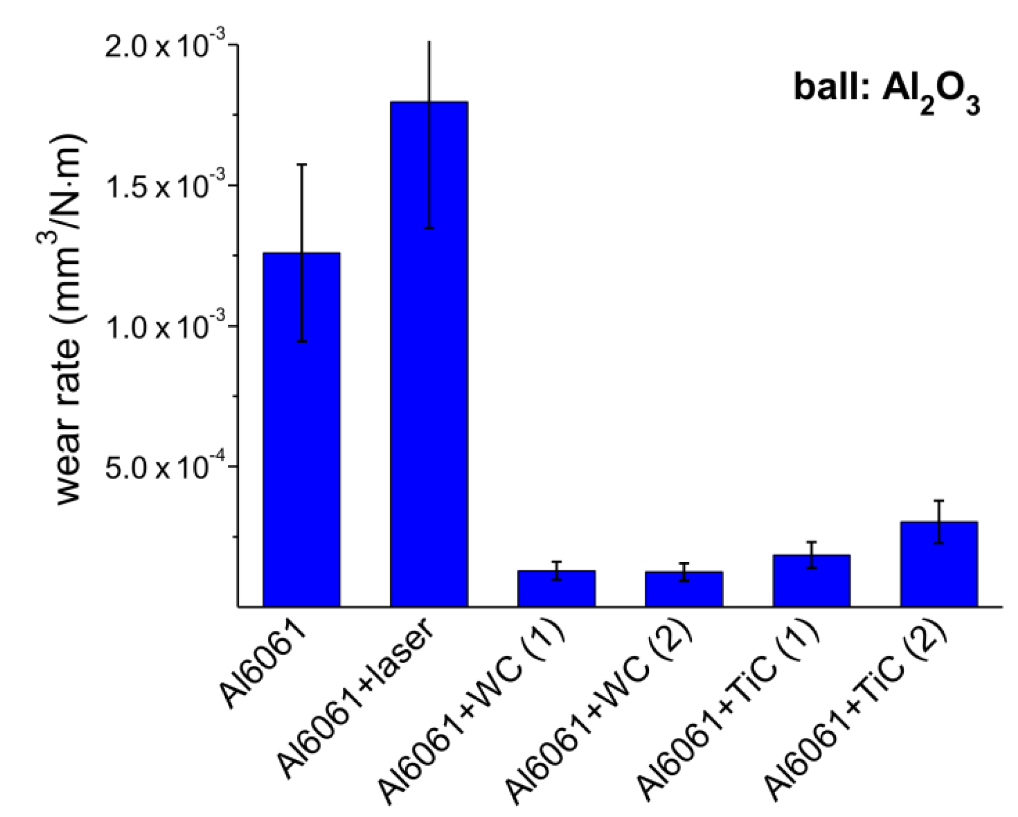
3.4. Wear Resistance
4. Conclusions
Author Contributions
Funding
Conflicts of Interest
References
- Ivanov, Y.F.; Gromov, V.E.; Konovalov, S.V.; Zagulyaev, D.V.; Petrikova, E.A.; Semin, A.P. Modification of structure and surface properties of hypoeutectic silumin by intense pulse electron beams. Prog. Phys. Met. 2018, 19, 195–222. [Google Scholar] [CrossRef] [Green Version]
- Wahab, J.A.; Ghazali, M.J. Erosion resistance of laser textured plasma-sprayed Al2O3-13%TiO2 coatings on mild steel. Wear 2019, 432–433, 202937. [Google Scholar] [CrossRef]
- Kümmel, D.; Hamann-Schroer, M.; Hetzner, H.; Schneider, J. Tribological behavior of nanosecond-laser surface textured Ti6Al4V. Wear 2019, 422–423, 261–268. [Google Scholar] [CrossRef] [Green Version]
- Salguero, J.; Del Sol, I.; Vazquez-Martinez, J.M.; Schertzer, M.J.; Iglesias, P. Effect of laser parameters on the tribological behavior of Ti6Al4V titanium microtextures under lubricated conditions. Wear 2019, 426–427, 1272–1279. [Google Scholar] [CrossRef]
- Sanjeev, K.C.; Nezhadfar, P.D.; Phillips, C.; Kennedy, M.S.; Shamsaei, N.; Jackson, R.L. Tribological behavior of 17-4 PH stainless steel fabricated by traditional manufacturing and laser-based additive manufacturing methods. Wear 2019, 440–441, 203100. [Google Scholar] [CrossRef]
- Riquelme, A.; Rodrigo, P.; Escalera-Rodríguez, M.D.; Rams, J. Additively Manufactured Al/SiC Cylindrical Structures by Laser Metal Deposition. Materials 2020, 13, 3331. [Google Scholar] [CrossRef]
- Dilawary, S.A.A.; Motallebzadeh, A.; Houdková, Š.; Medlin, R.; Haviar, S.; Lukáč, F.; Afzal, M.; Cimenoglu, H. Modification of M2 hardfacing: Effect of molybdenum alloying and laser surface melting on microstructure and wear performance. Wear 2018, 404–405, 111–121. [Google Scholar] [CrossRef]
- Yang, K.; Li, J.; Wang, Q.Y.; Li, Z.; Jiang, Y.; Bao, Y. Effect of laser remelting on microstructure and wear resistance of plasma sprayed Al2O3-40%TiO2 coating. Wear 2019, 426–427, 314–318. [Google Scholar] [CrossRef]
- Piasecki, A.; Kotkowiak, M.; Makuch, N.; Kulka, M. Wear behavior of self-lubricating boride layers produced on Inconel 600-alloy by laser alloying. Wear 2019, 426–427, 919–933. [Google Scholar] [CrossRef]
- Vandoni, L.; Demir, A.G.; Previtali, B.; Lecis, N.; Ugues, D. Wear Behavior of Fiber Laser Textured TiN Coatings in a Heavy Loaded Sliding Regime. Materials 2012, 5, 2360–2382. [Google Scholar] [CrossRef]
- Roy, T.; Lai, Q.; Abrahams, R.; Mutton, P.; Paradowska, A.; Soodi, M.; Yan, W. Effect of deposition material and heat treatment on wear and rolling contact fatigue of laser cladded rails. Wear 2018, 412–413, 69–81. [Google Scholar] [CrossRef]
- Roy, T.; Abrahams, R.; Paradowska, A.; Lai, Q.; Mutton, P.; Soodi, M.; Fasihi, P.; Yan, W. Evaluation of the mechanical properties of laser cladded hypereutectoid steel rails. Wear 2019, 432–433, 202930. [Google Scholar] [CrossRef]
- Chen, Y.; Zhao, X.; Liu, P.; Pan, R.; Ren, R. Influences of local laser quenching on wear performance of D1 wheel steel. Wear 2018, 414–415, 243–250. [Google Scholar] [CrossRef]
- Vreeling, J.A. Laser Melt Injection of Ceramic Particles in Metals. Ph.D. Thesis, University of Groningen, Groningen, The Netherlands, 2001. [Google Scholar]
- Pei, Y.T.; Ocelik, V.; De Hosson, J.T.M. SiCp/Ti6Al4V functionally graded materials produced by laser melt injection. Acta Mater. 2002, 50, 2035–2051. [Google Scholar] [CrossRef]
- Anandkumar, R.; Almeida, A.; Vilar, R. Microstructure and sliding wear resistance of an Al-12 wt% Si/TiC laser clad coating. Wear 2012, 282–283, 31–39. [Google Scholar] [CrossRef]
- Vreeling, J.A.; Ocelik, V.; Pei, Y.T.; van Agterveld, D.T.L.; De Hosson, J.T.M. Laser melt injection in aluminum alloys: On the role of the oxide skin. Acta Mater. 2000, 48, 4225–4233. [Google Scholar] [CrossRef] [Green Version]
- Vreeling, J.A.; Ocelik, V.; Hamstra, G.A.; Pei, Y.T.; De Hosson, J.T.M. In-situ microscopy investigation of failure mechanisms in Al/SiCp MMC produced by laser embedding. Scr. Mater. 2000, 42, 589–595. [Google Scholar] [CrossRef]
- Ocelik, V.; Matthews, D.; De Hosson, J.T.M. Sliding wear resistance of metal matrix composite layers prepared by high power laser. Surf. Coat. Tech. 2005, 197, 303–315. [Google Scholar] [CrossRef]
- Kaplan, A.F.H.; Liedl, G.; Zimmermann, J.; Schuocker, D. Laser dispersing of TiC-powder into Al-substrates. Lasers Eng. 1998, 7, 165–178. [Google Scholar]
- Li, F.; Gao, Z.; Zhang, Y.; Chen, Y. Alloying effect of titanium on WCp/Al composite fabricated by coincident wire-powder laser deposition. Mater. Des. 2016, 93, 370–378. [Google Scholar] [CrossRef]
- Kang, N.; El Mansori, M.; Lu, J.L.; Lin, X.; Huang, W.D. Effect of selective post-aging treatment on subsurface damage of quasicrystal reinforced Al composite manufactured by selective laser melting. Wear 2019, 426–427, 934–941. [Google Scholar] [CrossRef]
- Jendrzejewski, R.; Van Acker, K.; Vanhoyweghen, D.; Śliwiński, G. Metal matrix composite production by means of laser dispersing of SiC and WC powder in Al alloy. Appl. Surf. Sci. 2009, 255, 5584–5587. [Google Scholar] [CrossRef]
- Jendrzejewski, R.; Van Acker, K.; Vanhoyweghen, D. Laser dispersing of ceramic powders into Al-alloys. Proc. SPIE 2007, 6598, 65980D. [Google Scholar] [CrossRef]
- Jendrzejewski, R. Laser dispersing of carbide powders in Ti-6Al-4V alloy. Proc. SPIE 2013, 8703, 87030K. [Google Scholar] [CrossRef]
- Jendrzejewski, R.; Śliwiński, G. Laser dispersing of WC and TiC powders in light metal alloys for wear resistance enhancement. Proc. SPIE 2015, 9447, 94470G. [Google Scholar] [CrossRef]
- Rohde, M.; Dimitrova, D. Modelling of laser surface alloying and dispersing of ceramics. Laser Photon Rev. 2008, 2, 290–298. [Google Scholar] [CrossRef]
- Li, F.Q.; Li, L.Q.; Chen, Y.B. Arc enhanced laser melt injection WC particles on Al surface. Surf. Eng. 2013, 29, 296–299. [Google Scholar] [CrossRef]
- Dobrzański, L.A.; Tański, T.; Dobrzańska-Danikiewicz, A.D.; Jonda, E.; Bonek, M.; Drygała, A. Structures, properties and development trends of laser-surface-treated hot-work steels, light metal alloys and polycrystalline silicon. In Laser Surface Engineering, Processes and Applications; Lawrence, J., Waugh, D.G., Eds.; Elsevier: Amsterdam, The Netherlands, 2015; pp. 3–32. [Google Scholar] [CrossRef]
- Betts, J.C. Laser surface modification of aluminium and magnesium alloys. In Surface Engineering of Light Alloys. Aluminium, Magnesium and Titanium Alloys; Dong, H., Ed.; Woodhead Publishing Limited: Cambridge, UK; CRC Press: Boca Raton, FL, USA, 2010; pp. 444–474. [Google Scholar] [CrossRef]


| Powder | Alloy | Laser | Wavelength (nm) | Beam Profile | Substrate Preheating | Single/Multi-Tracks | References |
|---|---|---|---|---|---|---|---|
| SiC | Pure Al | Nd:YAG | 1064 | Gaussian | Yes | Single | [14,17,18] |
| SiC | Al–8Si | Nd:YAG | 1064 | Gaussian | Yes | Single | [19] |
| TiC | AlSi7 | CO2 | 10,600 | Multimode | No data | Single | [20] |
| SiC | Al6061 | Diode | 808 and 940 | Top-hat | Yes | Multi | [23,24] |
| TiC, WC | Al6061 | Yb:YAG | 1030 | Top-hat | No | Single | [26] |
| SiC, TiC, WC | Al6061 | Yb:YAG | 1030 | Top-hat | No | Multi | This work |
| Alloy | Chemical Composition | ρ (kg/m3) | Tm (°C) |
|---|---|---|---|
| Al6061 | 0.8–1.2% Mg, ≤0.7% Fe, 0.4–0.8% Si, 0.15–0.4% Cu, ≤0.25% Zn, ≤0.15% Mn, 0.04–0.35% Cr, ≤0.15% Ti, bal. Al | 2700 | 585 |
| Powder | Grain Shape | Grain Size (µm) | ρ (kg/m3) | Tm (°C) |
|---|---|---|---|---|
| SiC | Irregular | ~80 (60–100) | 3200 | 2730 |
| TiC | Irregular | ~95 (50–150) | 4900 | 3160 |
| WC | Spherical | ~100 (45–150) | 16,400 | 2870 |
| Scanning Velocity vsc (mm/s) | Powder Feed-Rate mp (g/min) | Laser Power P (W) | Laser Beam Spot Size dl (mm) | Laser Beam Intensity I (W/mm2) | Laser Energy Density E0 (J/mm2) | |||
|---|---|---|---|---|---|---|---|---|
| TiC | WC | SiC | ||||||
| Min | 5 | 1.6 | 15.9 | 1.3 | 800 | 1.3 | 110 | 33 |
| Max | 30 | 6.5 | 30 | 4 | 5000 | 3.1 | 2810 | 329 |
| No. | E0 (J/mm2) | vsc (mm/s) | mp (g/min) | Sample Cross-Section |
|---|---|---|---|---|
| 1 | 123 | 10 | 5.0 | 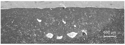 |
| 2 | 152 | 10 | 5.0 | 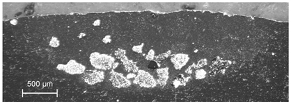 |
| 3 | 123 | 10 | 5.0 | 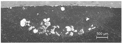 |
| 4 | 246 | 5 | 5.0 | 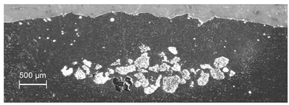 |
| 5 | 329 | 5 | 5.0 | 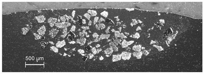 |
| 6 | 123 | 10 | 6.5 |  |
© 2020 by the authors. Licensee MDPI, Basel, Switzerland. This article is an open access article distributed under the terms and conditions of the Creative Commons Attribution (CC BY) license (http://creativecommons.org/licenses/by/4.0/).
Share and Cite
Jendrzejewski, R.; Łubiński, J.; Śliwiński, G. Wear Resistance Enhancement of Al6061 Alloy Surface Layer by Laser Dispersed Carbide Powders. Materials 2020, 13, 3683. https://doi.org/10.3390/ma13173683
Jendrzejewski R, Łubiński J, Śliwiński G. Wear Resistance Enhancement of Al6061 Alloy Surface Layer by Laser Dispersed Carbide Powders. Materials. 2020; 13(17):3683. https://doi.org/10.3390/ma13173683
Chicago/Turabian StyleJendrzejewski, Rafał, Jacek Łubiński, and Gerard Śliwiński. 2020. "Wear Resistance Enhancement of Al6061 Alloy Surface Layer by Laser Dispersed Carbide Powders" Materials 13, no. 17: 3683. https://doi.org/10.3390/ma13173683