A Facile Method for the Generation of Fe3C Nanoparticle and Fe-Nx Active Site in Carbon Matrix to Achieve Good Oxygen Reduction Reaction Electrochemical Performances


Abstract
:
1. Introduction
2. Experimental Section
2.1. Materials
2.2. Catalysts Preparation
2.3. Characterization
2.4. Electrochemical Measurements
3. Results and Discussion
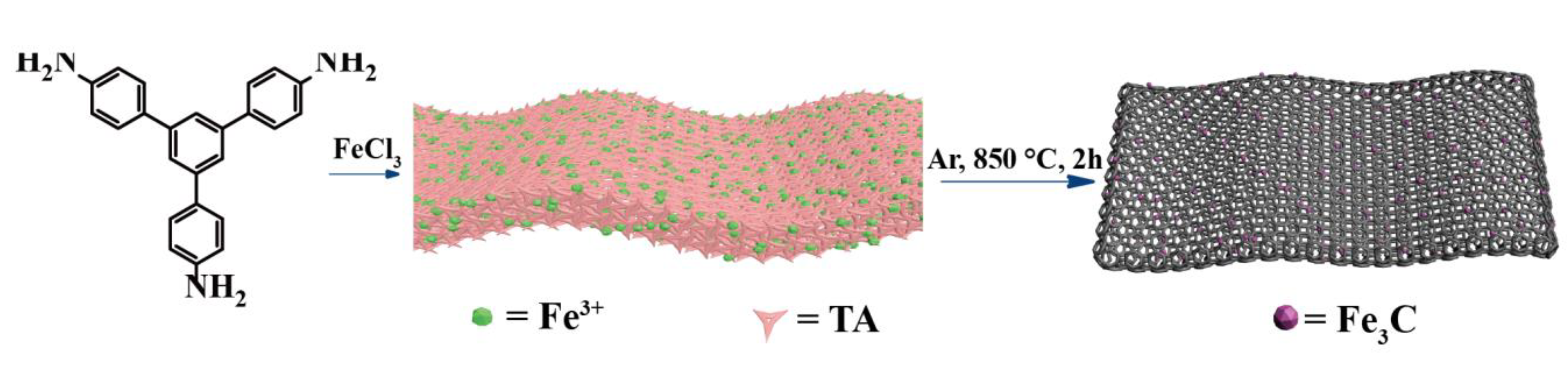
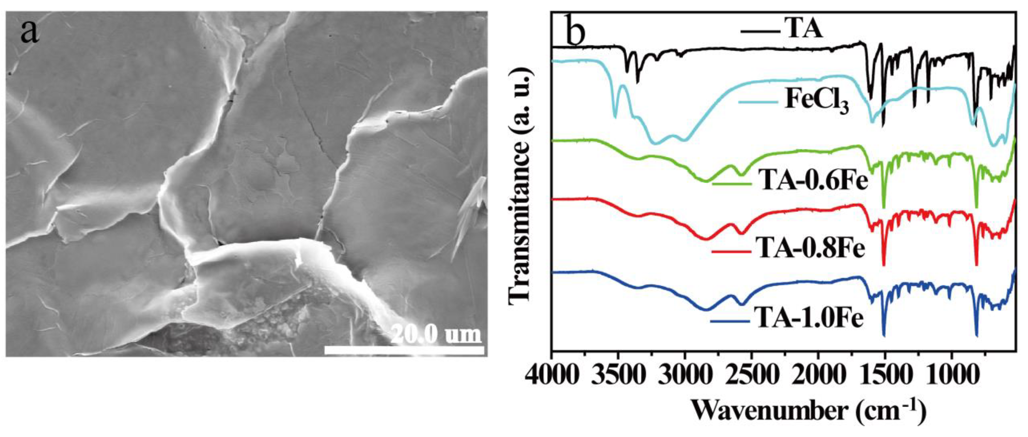
3.1. Characterization of Metallosupramolecular Polymer Precursors
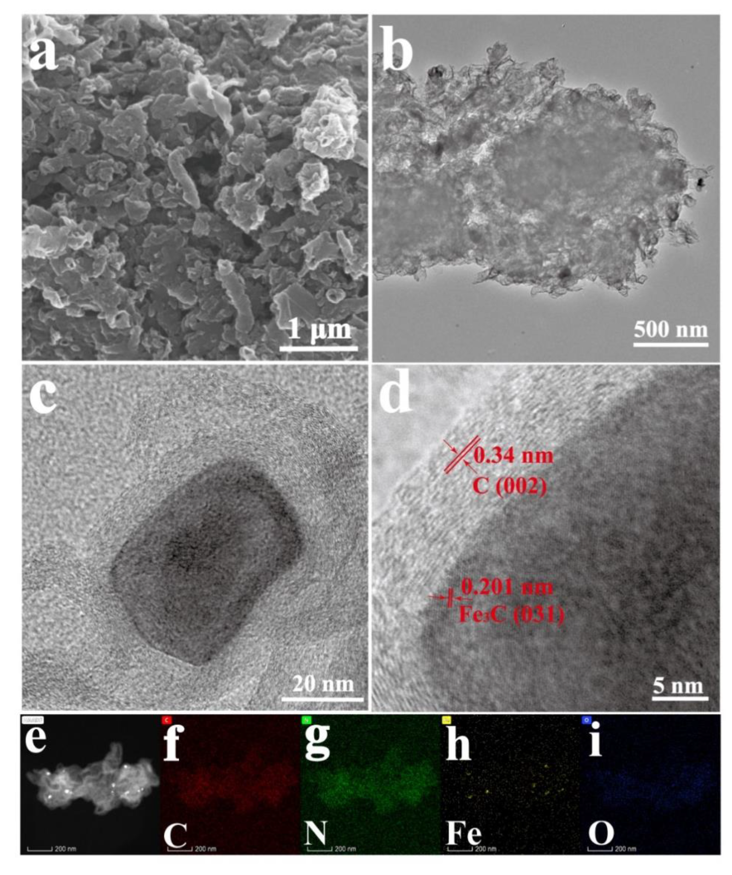
3.2. Structure and Composition of CNSs
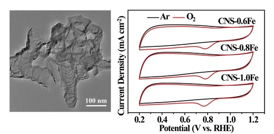
3.3. ORR Performance of CNSs
4. Conclusions
Supplementary Materials
Author Contributions
Funding
Conflicts of Interest
References
- Shao, M.; Chang, Q.; Dodelet, J.-P.; Chenitz, R. Recent Advances in Electrocatalysts for Oxygen Reduction Reaction. Chem. Rev. 2016, 116, 3594–3657. [Google Scholar] [CrossRef] [Green Version]
- Lu, X.; Wang, D.; Ge, L.; Xiao, L.; Zhang, H.; Liu, L.; Zhang, J.; An, M.; Yang, P. Enriched graphitic N in nitrogen-doped graphene as a superior metal-free electrocatalyst for the oxygen reduction reaction. New J. Chem. 2018, 42, 19665–19670. [Google Scholar] [CrossRef]
- Asahi, M.; Yamazaki, S.-I.; Morimoto, Y.; Itoh, S.; Ioroi, T. Crystal structure and oxygen reduction reaction (ORR) activity of copper(II) complexes of pyridylmethylamine ligands containing a carboxy group. Inorganica Chim. Acta 2018, 471, 91–98. [Google Scholar] [CrossRef]
- Bukka, S.; Badam, R.; Vedarajan, R.; Matsumi, N. Photo-generation of ultra-small Pt nanoparticles on carbon-titanium dioxide nanotube composites: A novel strategy for efficient ORR activity with low Pt content. Int. J. Hydrogen Energy 2019, 44, 4745–4753. [Google Scholar] [CrossRef]
- Banhamd, D.; Ye, S.; Pei, K.; Ozaki, J.-I.; Kishimoto, T.; Imashiro, Y. A review of the stability and durability of non-precious metal catalysts for the oxygen reduction reaction in proton exchange membrane fuel cells. J. Power Sources 2015, 285, 334–348. [Google Scholar] [CrossRef]
- Wu, J.; Wang, J.; Lv, X.; Wang, X. A thin slice-like Co3O4/N-doped graphene hybrid as an efficient catalyst for oxygen reduction reaction. Inorg. Chem. Commun. 2019, 106, 128–134. [Google Scholar] [CrossRef]
- Yan, Z.; Dai, C.; Zhang, M.; Lv, X.; Zhao, X.; Xie, J. Nitrogen doped porous carbon with iron promotion for oxygen reduction reaction in alkaline and acidic media. Int. J. Hydrogen Energy 2019, 44, 4090–4101. [Google Scholar] [CrossRef]
- Chu, Y.; Gu, L.; Du, H.; Qu, K.; Zhang, Y.; Zhao, J.; Xie, Y. The synthesis of phenanthroline and bipyridine based ligand for the preparation of Fe-Nx/C type electrocatalyst for oxygen reduction. Int. J. Hydrogen Energy 2018, 43, 21810–21823. [Google Scholar] [CrossRef]
- Hassan, D.; El-Safty, S.A.; Khalil, K.A.; Dewidar, M.; Abu El-Magd, G. Carbon Supported Engineering NiCo2O4 Hybrid Nanofibers with Enhanced Electrocatalytic Activity for Oxygen Reduction Reaction. Materials 2016, 9, 759. [Google Scholar] [CrossRef] [Green Version]
- Abdelwahab, A.; Carrasco-Marín, F.; Pérez-Cadenas, A.F. Binary and Ternary 3D Nanobundles Metal Oxides Functionalized Carbon Xerogels as Electrocatalysts toward Oxygen Reduction Reaction. Materials 2020, 13, 3531. [Google Scholar] [CrossRef]
- Mahammed, A.; Gross, Z. Metallocorroles as Electrocatalysts for the Oxygen Reduction Reaction (ORR). Isr. J. Chem. 2016, 56, 756–762. [Google Scholar] [CrossRef]
- Dou, S.; Wang, X.; Wang, S. Rational Design of Transition Metal-Based Materials for Highly Effcient Electrocatalysis. Small Methods 2019, 3, 1800211. [Google Scholar] [CrossRef] [Green Version]
- Toh, R.J.; Poh, H.L.; Sofer, Z.; Pumera, M. Transition Metal (Mn, Fe, Co, Ni)-Doped Graphene Hybrids for Electrocatalysis. Chem. Asian J. 2013, 8, 1295–1300. [Google Scholar] [CrossRef] [PubMed]
- Peng, H.; Liu, F.; Liu, X.; Liao, S.; You, C.; Tian, X.; Nan, H.; Luo, F.; Song, H.; Fu, Z.; et al. Effect of Transition Metals on the Structure and Performance of the Doped Carbon Catalysts Derived From Polyaniline and Melamine for ORR Application. ACS Catal. 2014, 4, 3797–3805. [Google Scholar] [CrossRef]
- Eisenberg, D.; Slot, T.K.; Rothenberg, G. Understanding Oxygen Activation on Metal- and Nitrogen-Codoped Carbon Catalysts. ACS Catal. 2018, 8, 8618–8629. [Google Scholar] [CrossRef]
- Guo, J.; Cheng, Y.; Xiang, Z. Confined-Space-Assisted Preparation of Fe3O4-Nanoparticle-Modified Fe–N–C Catalysts Derived from a Covalent Organic Polymer for Oxygen Reduction. ACS Sustain. Chem. Eng. 2017, 5, 7871–7877. [Google Scholar] [CrossRef]
- Wang, Q.; Zhou, Z.-Y.; Lai, Y.-J.; You, Y.; Liu, J.-G.; Wu, X.-L.; Terefe, E.; Chen, C.; Song, L.; Rauf, M.; et al. Phenylenediamine-Based FeNx/C Catalyst with High Activity for Oxygen Reduction in Acid Medium and Its Active-Site Probing. J. Am. Chem. Soc. 2014, 136, 10882–10885. [Google Scholar] [CrossRef]
- Wang, M.-Q.; Ye, C.; Wang, M.; Li, T.-H.; Yu, Y.-N.; Bao, S.-J. Synthesis of M (Fe3C, Co, Ni)-porous carbon frameworks as high-efficient ORR catalysts. Energy Storage Materials. 2018, 11, 112–117. [Google Scholar] [CrossRef]
- Tei, G.; Tamaki, T.; Hayashi, T.; Nakajima, K.; Sakai, A.; Yotsuhashi, S.; Ogawa, T. Oxygen Reduction Reaction (ORR) Activity of a Phenol-Substituted Linear FeIII-Porphyrin Dimer. Eur. J. Inorg. Chem. 2017, 2017, 3229–3232. [Google Scholar] [CrossRef]
- Li, W.; Sun, L.; Hu, R.; Liao, W.; Li, Z.; Li, Y.; Guo, C. Surface Modification of Multi-Walled Carbon Nanotubes via Hemoglobin-Derived Iron and Nitrogen-Rich Carbon Nanolayers for the Electrocatalysis of Oxygen Reduction. Materials 2017, 10, 564. [Google Scholar] [CrossRef] [Green Version]
- Li, Y.; Li, Z.; Wu, Y.; Wu, H.; Zhang, H.; Wu, T.; Yuan, C.; Xu, Y.; Zeng, B.; Dai, L. Carbon particles co-doped with N, B and Fe from metal-organic supramolecular polymers for boosted oxygen reduction performance. J. Power Sources 2019, 412, 623–630. [Google Scholar] [CrossRef]
- Gu, W.; Hu, L.; Li, J.; Wang, E. Recent Advancements in Transition Metal-Nitrogen-Carbon Catalysts for Oxygen Reduction Reaction. Electroanalysis 2018, 30, 1217–1228. [Google Scholar] [CrossRef]
- Zhang, Z.; Li, H.; Liu, H. Insight into the adsorption of tetracycline onto amino and amino–Fe3+ gunctionalized mesoporous silica: Effect of functionalized groups. J. Environ. Sci. 2018, 65, 171–178. [Google Scholar] [CrossRef]
- Li, L.; Yuan, C.; Zhou, D.; Ribbe, A.E.; Kittilstved, K.R.; Thayumanavan, S. Utilizing Reversible Interactions in Polymeric Nanoparticles To Generate Hollow Metal-Organic Nanoparticles. Angew. Chem. 2015, 127, 13183–13187. [Google Scholar] [CrossRef]
- Zuo, J.-C.; Tong, S.-R.; Yu, X.-L.; Wu, L.-Y.; Cao, C.-Y.; Ge, M.; Song, W.-G. Fe3+ and amino functioned mesoporous silica: Preparation, structural analysis and arsenic adsorption. J. Hazard. Mater. 2012, 235, 336–342. [Google Scholar] [CrossRef]
- Jiang, W.-J.; Gu, L.; Li, L.; Zhang, Y.; Zhang, X.; Zhang, L.-J.; Wang, J.; Hu, J.-S.; Wei, Z.; Wan, L.-J. Understanding the High Activity of Fe–N–C Electrocatalysts in Oxygen Reduction: Fe/Fe3C Nanoparticles Boost the Activity of Fe–Nx. J. Am. Chem. Soc. 2016, 138, 3570–3578. [Google Scholar] [CrossRef]
- Wei, J.; Liang, Y.; Hu, Y.; Kong, B.; Simon, G.P.; Zhang, J.; Jiang, S.P.; Wang, H. A Versatile Iron-Tannin-Framework Ink Coating Strategy to Fabricate Biomass-Derived Iron Carbide/Fe-N-Carbon Catalysts for Efficient Oxygen Reduction. Angew. Chem. Int. Ed. 2015, 55, 1355–1359. [Google Scholar] [CrossRef]
- Shen, H.; Gracia-Espino, E.; Xamxikamar, M.; Zang, K.; Luo, J.; Wang, L.; Gao, S.; Mamat, X.; Sanshuang, G.; Wagberg, T.; et al. Synergistic Effects between Atomically Dispersed Fe−N−C and C−S−C for the Oxygen Reduction Reaction in Acidic Media. Angew. Chem. Int. Ed. 2017, 56, 13800–13804. [Google Scholar] [CrossRef]
- Chang, Y.; Yuan, C.; Li, Y.; Liu, C.; Wu, T.; Zeng, B.; Xu, Y.; Thayumanavan, S. Controllable fabrication of a N and B co-doped carbon shell on the surface of TiO2 as a support for boosting the electrochemical performances. J. Mater. Chem. A 2017, 5, 1672–1678. [Google Scholar] [CrossRef]
- Hou, Y.; Huang, T.; Wen, Z.; Mao, S.; Cui, S.; Chen, J. Metal−Organic Framework-Derived Nitrogen-Doped Core-Shell-Structured Porous Fe/Fe3C@C Nanoboxes Supported on Graphene Sheets for Efficient Oxygen Reduction Reactions. Adv. Energy Mater. 2014, 4, 1400337. [Google Scholar] [CrossRef]
- Jiao, L.; Wan, G.; Zhang, R.; Zhou, H.; Yu, S.-H.; Jiang, H.-L. From Metal-Organic Frameworks to Single-Atom Fe Implanted N doped Porous Carbons: Efficient Oxygen Reduction in Both Alkaline and Acidic Media. Angew. Chem. Int. Ed. 2018, 57, 1–6. [Google Scholar] [CrossRef] [PubMed]
- Chang, Y.; Yuan, C.; Liu, C.; Mao, J.; Li, Y.; Wu, H.; Wu, Y.; Xu, Y.; Zeng, B.; Dai, L. B, N co-doped carbon from cross-linking induced self-organization of boronate polymer for supercapacitor and oxygen reduction reaction. J. Power Sources 2017, 365, 354–361. [Google Scholar] [CrossRef]
- Rouhet, M.; Bozdech, S.; Bonnefont, A.; Savinova, E.R. Influence of the proton transport on the ORR kinetics and on the H2O2 escape in three-dimensionally ordered electrodes. Electrochem. Commun. 2013, 33, 111–114. [Google Scholar] [CrossRef]
- Liu, S.-H.; Wu, J.-R.; Pan, C.-J.; Hwang, B.-J. Synthesis and characterization of carbon incorporated Fe-N/carbonsfor methanol-tolerant oxygen reduction reaction of polymer electrolyte fuel cells. J. Power Sources 2014, 250, 279–285. [Google Scholar] [CrossRef]
- Kosmala, T.; Bibent, N.; Sougrati, M.T.; Dražić, G.; Agnoli, S.; Jaouen, F.; Granozzi, G. Stable, Active, and Methanol-Tolerant PGM-Free Surfaces in an Acidic Medium: Electron Tunneling at Play in Pt/FeNC Hybrid Catalysts for Direct Methanol Fuel Cell Cathodes. ACS Catal. 2020, 10, 7475–7485. [Google Scholar] [CrossRef]
- Vecchio, C.L.; Sebastián, D.; Lázaro, M.J.; Aricò, A.S.; Baglio, V. Methanol-Tolerant M–N–C Catalysts for Oxygen Reduction Reactions in Acidic Media and Their Application in Direct Methanol Fuel Cells. Catalysts 2018, 8, 650. [Google Scholar] [CrossRef] [Green Version]


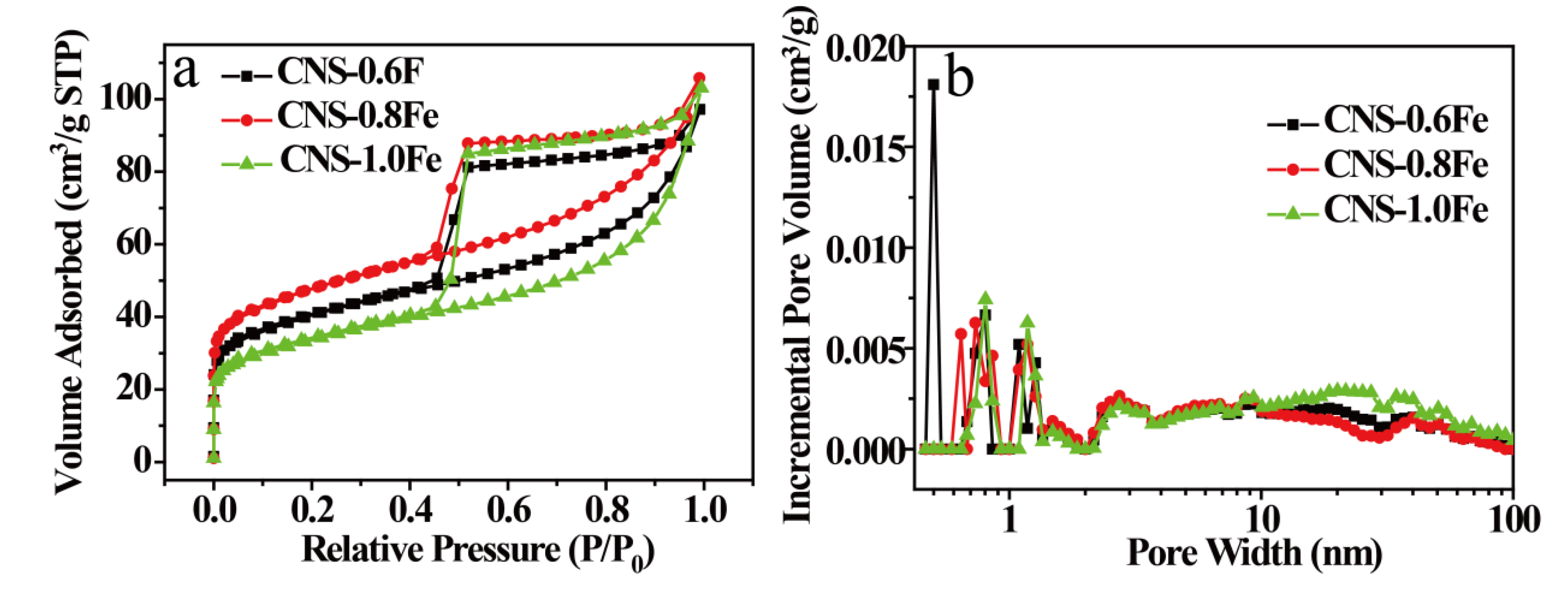
| Samples | SBET a [m2·g−1] | Smicro b [m2·g−1] | Smeso+macro c [m2·g−1] | Vtotal d [cm3·g−1] |
|---|---|---|---|---|
| CNS–0.6Fe | 167.86 | 73.36 | 94.49 | 0.16 |
| CNS–0.8Fe | 196.20 | 95.39 | 100.81 | 0.17 |
| CNS–1.0Fe | 145.20 | 62.43 | 82.77 | 0.17 |
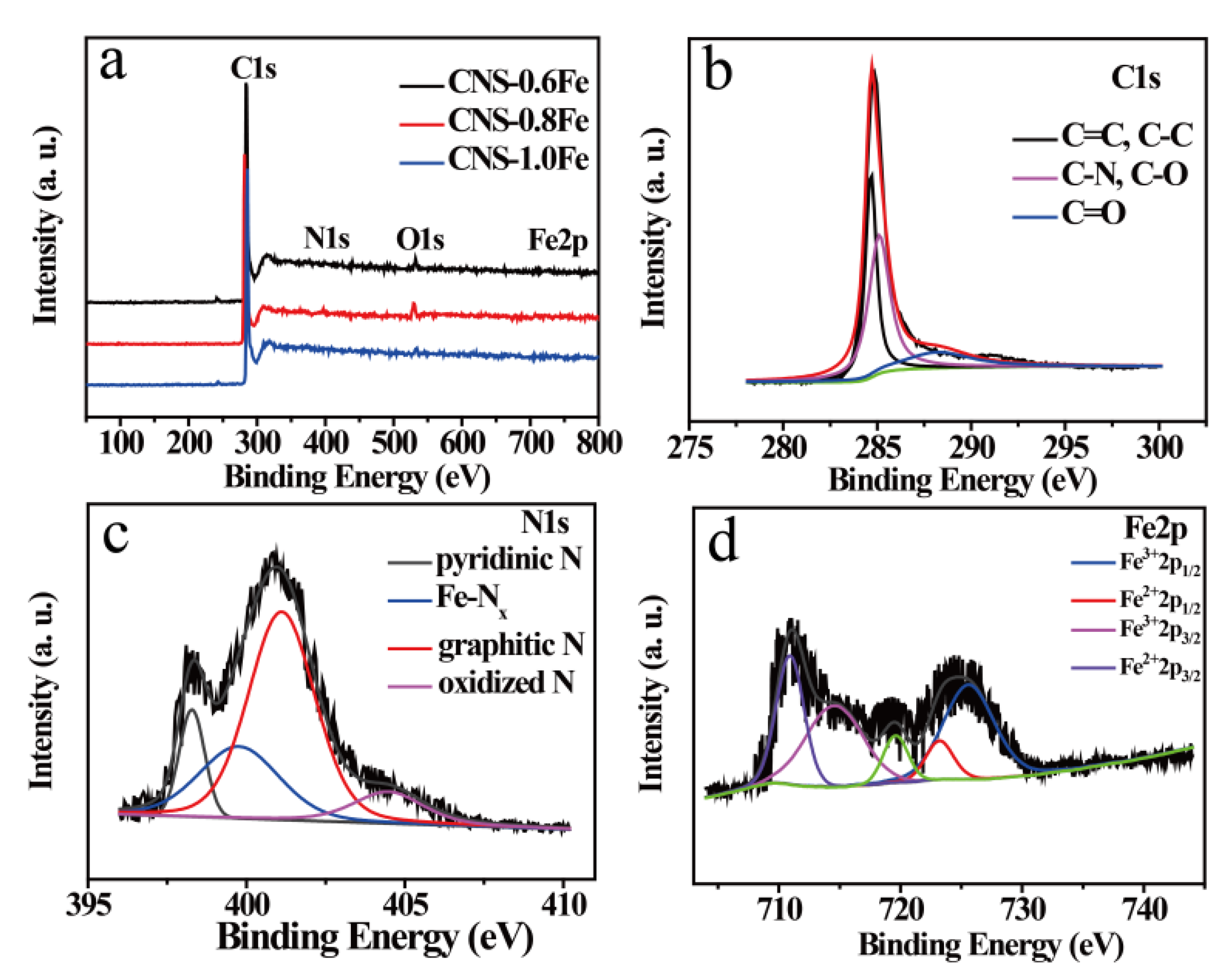
| Samples | N (at.%) a | |||
|---|---|---|---|---|
| Pyridinic N | Fe–Nx | Graphitic N | Oxidized N | |
| CNS-0.6Fe | 0.17 | 0.20 | 0.37 | 0.19 |
| CNS-0.8Fe | 0.28 | 0.43 | 0.89 | 0.21 |
| CNS-1.0Fe | 0.25 | 0.22 | 0.35 | 0.16 |
Publisher’s Note: MDPI stays neutral with regard to jurisdictional claims in published maps and institutional affiliations. |
© 2020 by the authors. Licensee MDPI, Basel, Switzerland. This article is an open access article distributed under the terms and conditions of the Creative Commons Attribution (CC BY) license (http://creativecommons.org/licenses/by/4.0/).
Share and Cite
Wu, Y.; Li, Y.; Yuan, C.; Dai, L. A Facile Method for the Generation of Fe3C Nanoparticle and Fe-Nx Active Site in Carbon Matrix to Achieve Good Oxygen Reduction Reaction Electrochemical Performances. Materials 2020, 13, 4779. https://doi.org/10.3390/ma13214779
Wu Y, Li Y, Yuan C, Dai L. A Facile Method for the Generation of Fe3C Nanoparticle and Fe-Nx Active Site in Carbon Matrix to Achieve Good Oxygen Reduction Reaction Electrochemical Performances. Materials. 2020; 13(21):4779. https://doi.org/10.3390/ma13214779
Chicago/Turabian StyleWu, Yuzhe, Yuntong Li, Conghui Yuan, and Lizong Dai. 2020. "A Facile Method for the Generation of Fe3C Nanoparticle and Fe-Nx Active Site in Carbon Matrix to Achieve Good Oxygen Reduction Reaction Electrochemical Performances" Materials 13, no. 21: 4779. https://doi.org/10.3390/ma13214779