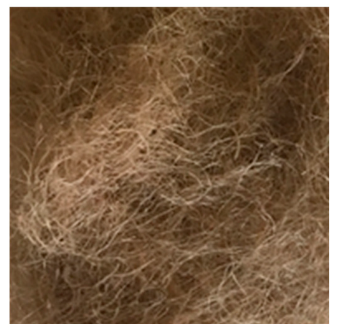
Figure 1.
Jute fibres (not to scale).
Figure 1.
Jute fibres (not to scale).
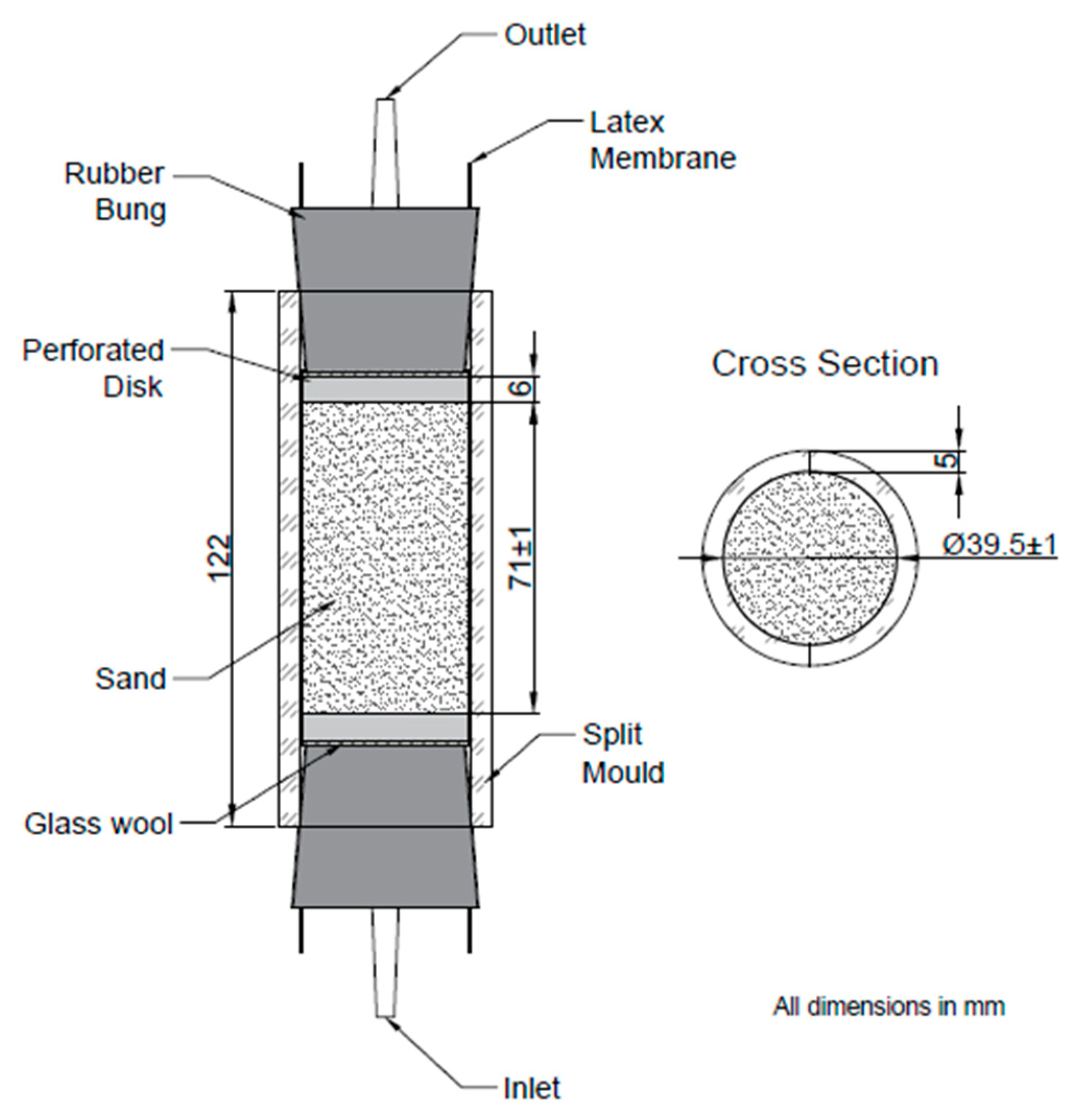
Figure 2.
Column assembly.
Figure 2.
Column assembly.
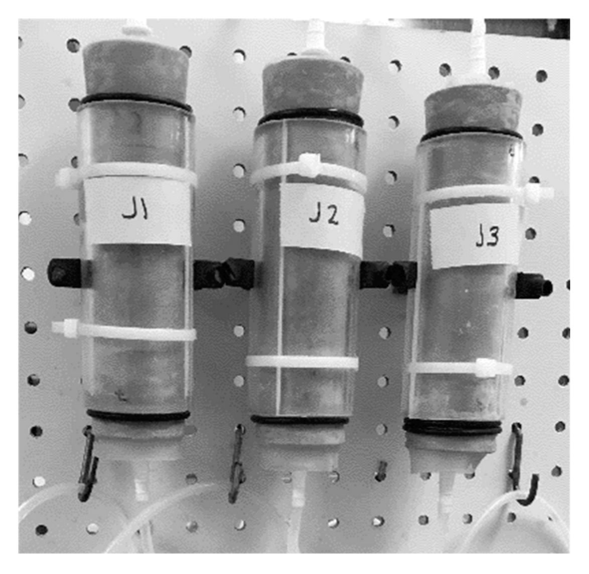
Figure 3.
Columns attached to frame.
Figure 3.
Columns attached to frame.
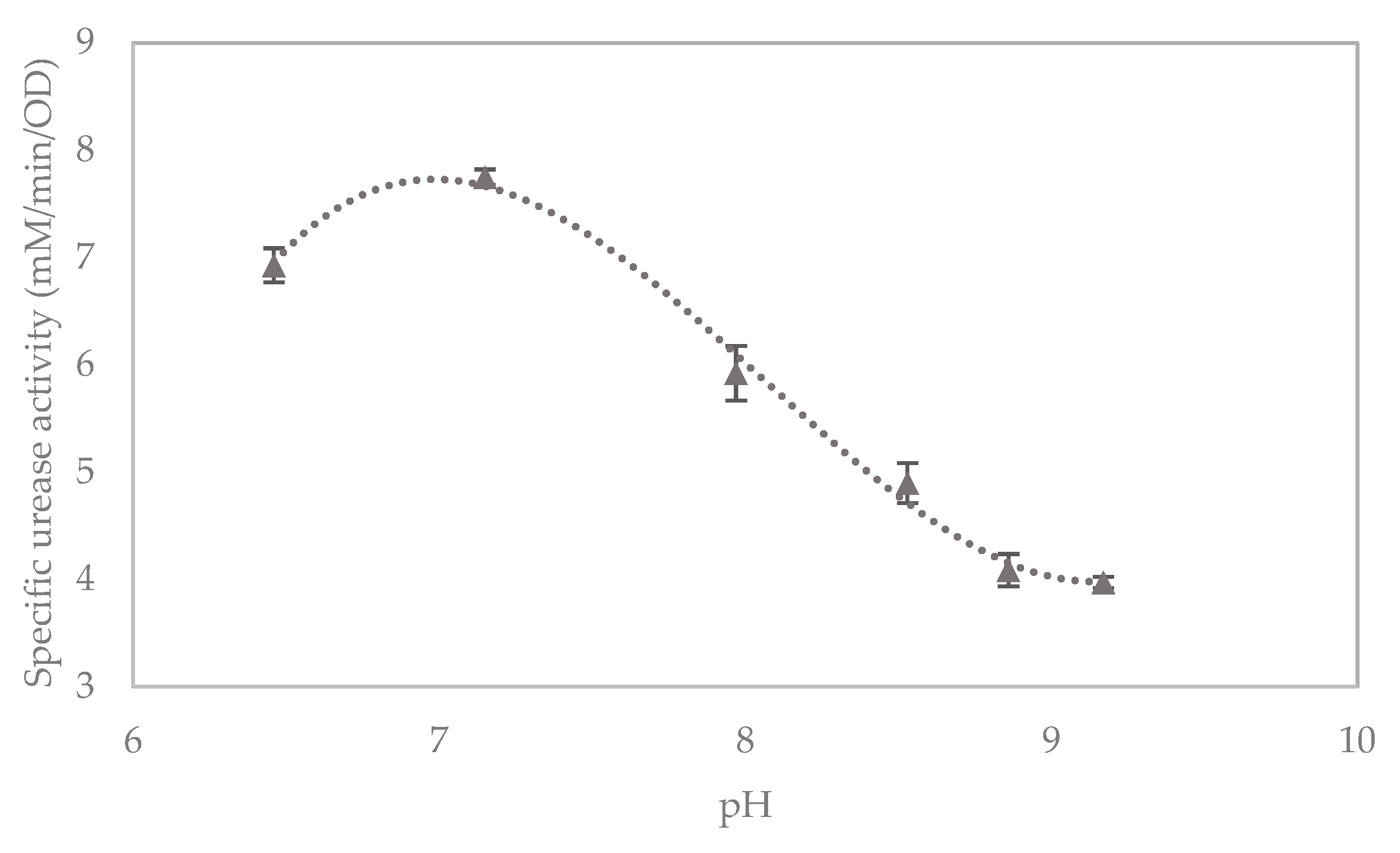
Figure 4.
Effect of pH on specific urease activity in liquid broth cultures, with error bars showing standard errors of the means.
Figure 4.
Effect of pH on specific urease activity in liquid broth cultures, with error bars showing standard errors of the means.
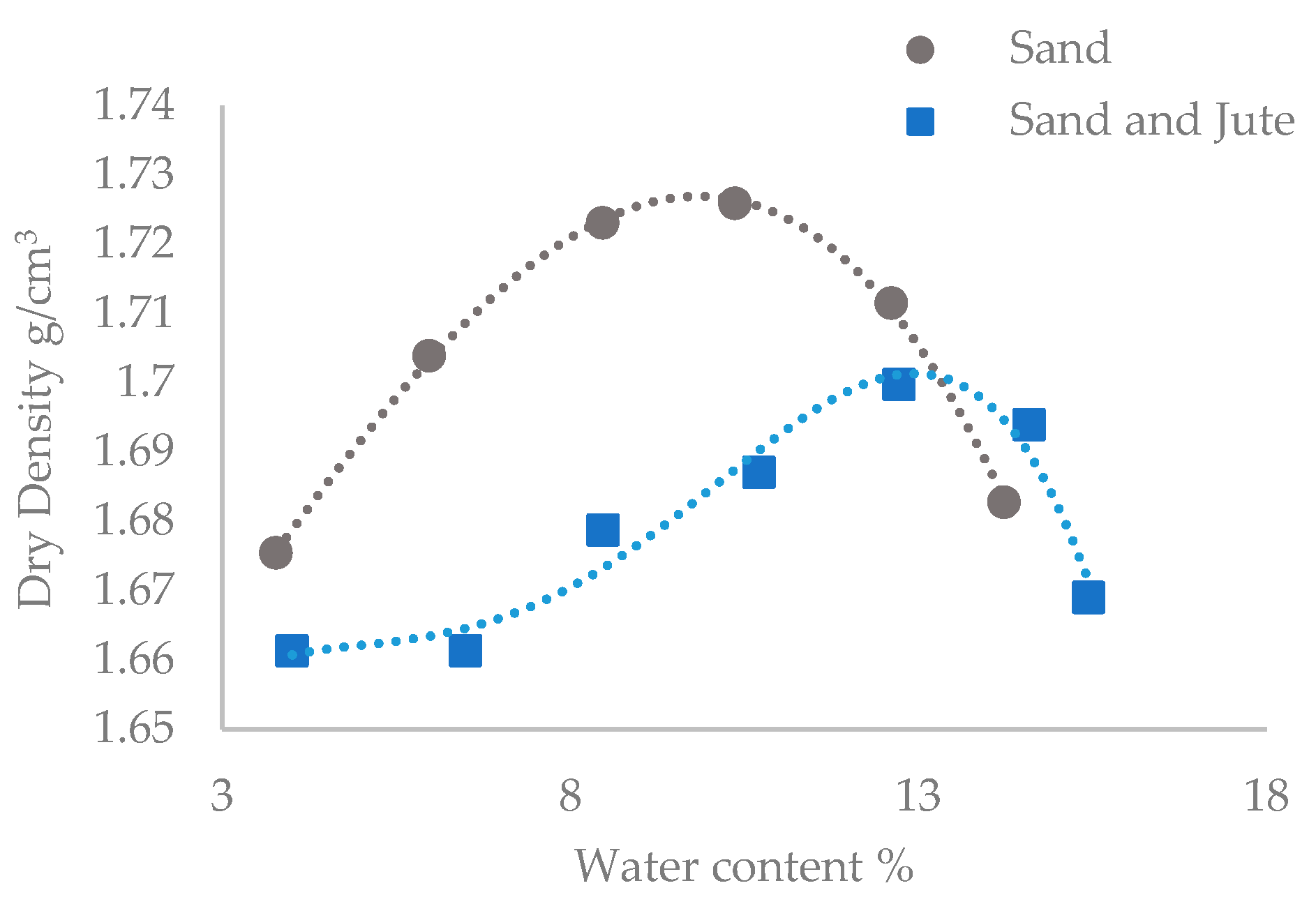
Figure 5.
Proctor compaction curves for sand only and fibre and sand mixtures.
Figure 5.
Proctor compaction curves for sand only and fibre and sand mixtures.
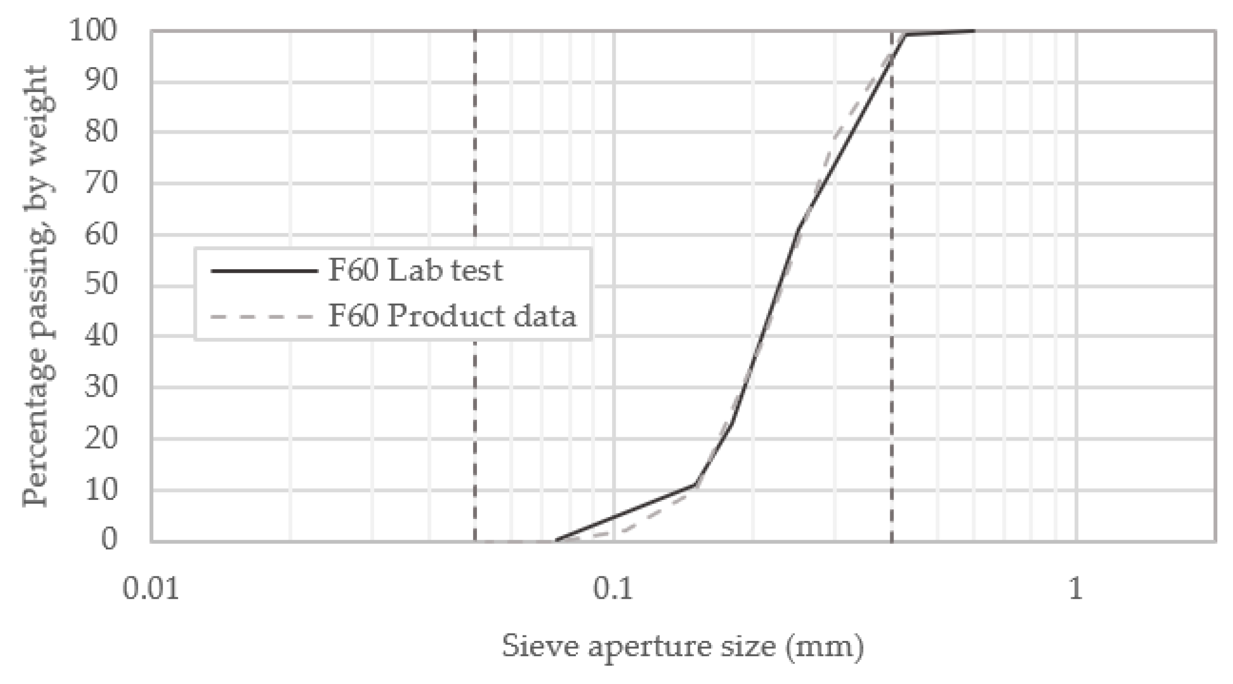
Figure 6.
Particle size distribution of F60 sand.
Figure 6.
Particle size distribution of F60 sand.
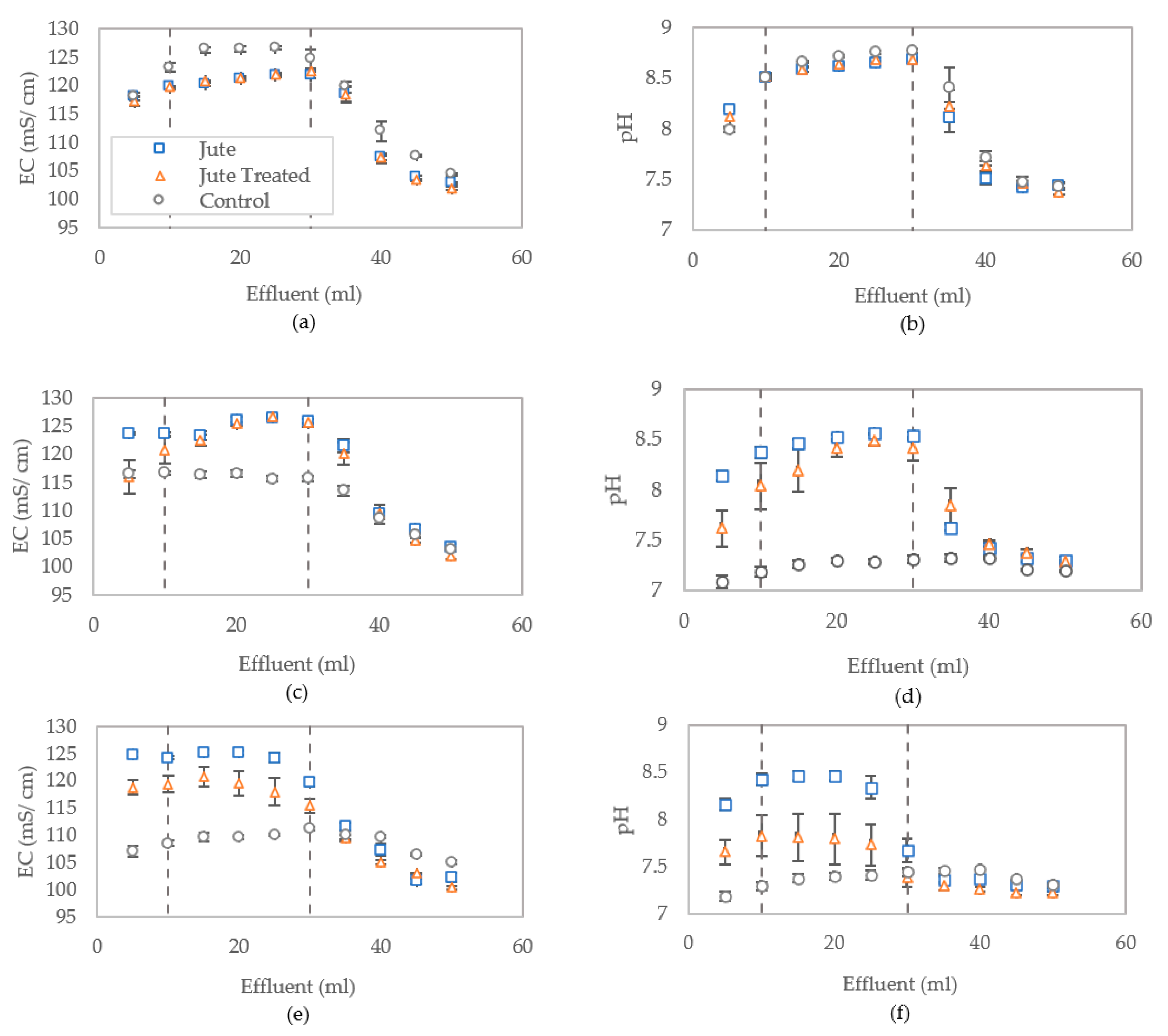
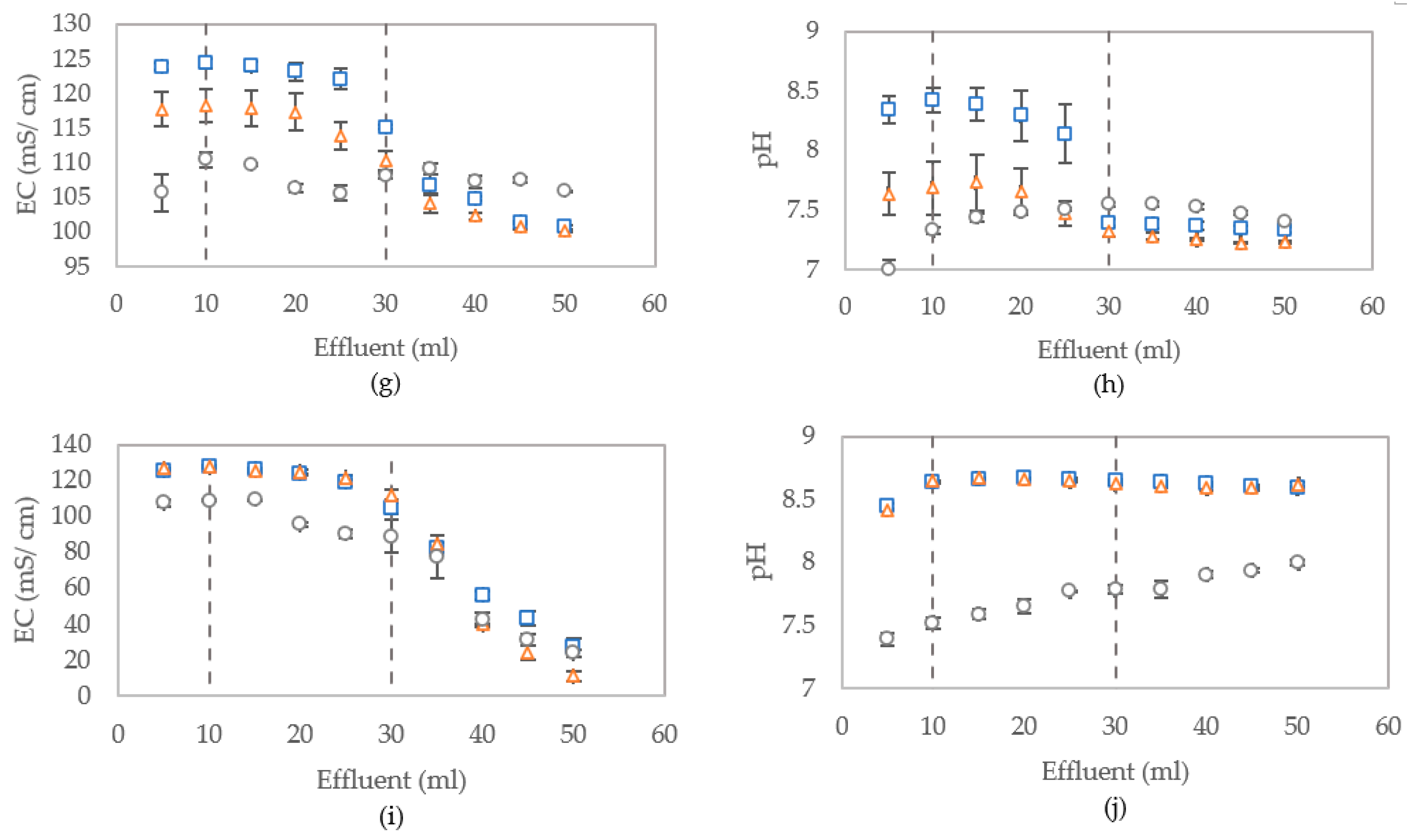
Figure 7.
Conductivity and pH of columns effluent measured following treatments 1 (a,b), 2 (c,d), 3 (e,f), 4 (g,h) and 5 (i,j), with error bars showing standard errors of the means for the triplicates.
Figure 7.
Conductivity and pH of columns effluent measured following treatments 1 (a,b), 2 (c,d), 3 (e,f), 4 (g,h) and 5 (i,j), with error bars showing standard errors of the means for the triplicates.
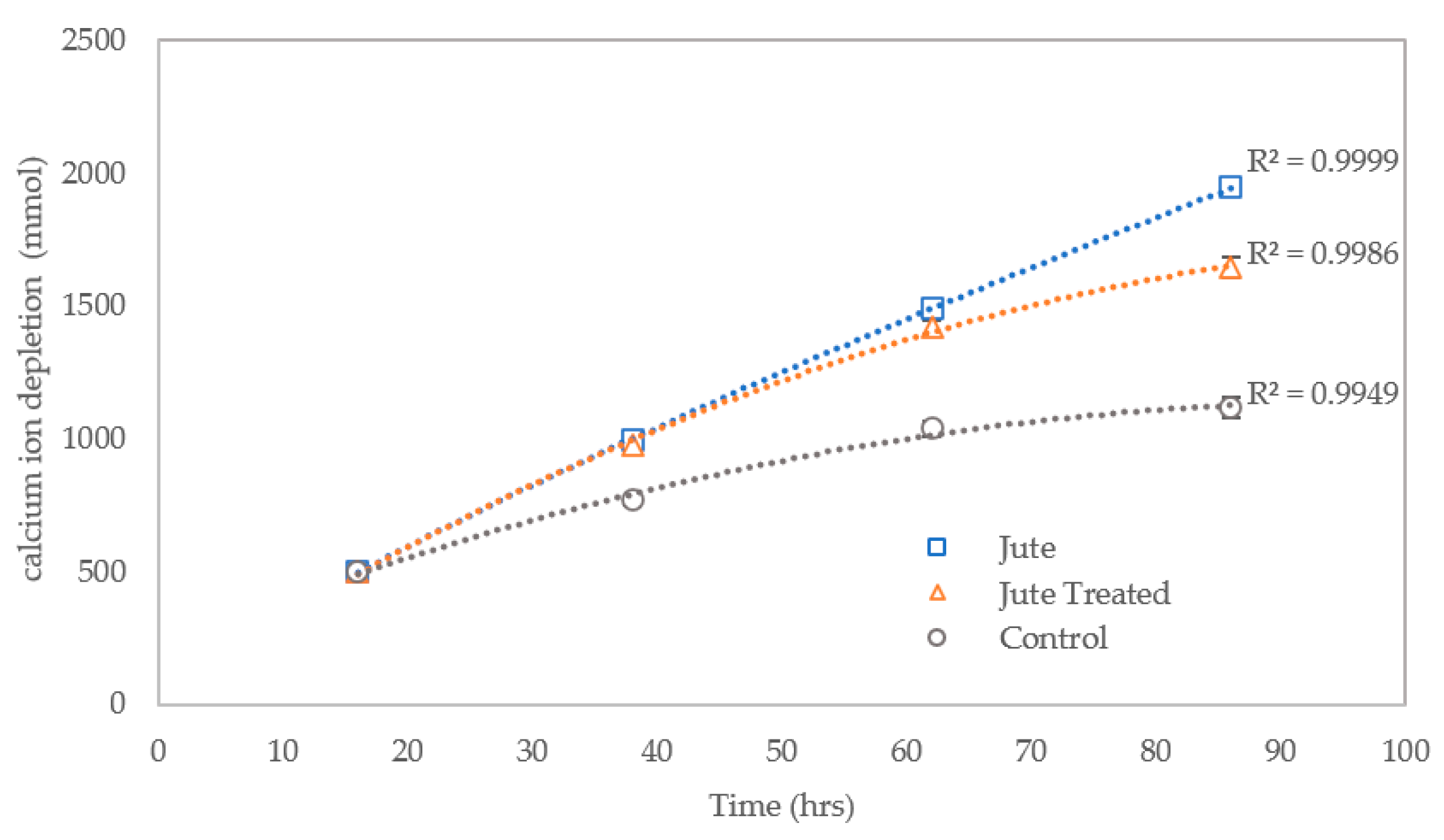
Figure 8.
Cumulative reduction in concentration of calcium ions in columns between cementation medium (CM) treatments one and four, with error bars showing standard errors of the means.
Figure 8.
Cumulative reduction in concentration of calcium ions in columns between cementation medium (CM) treatments one and four, with error bars showing standard errors of the means.
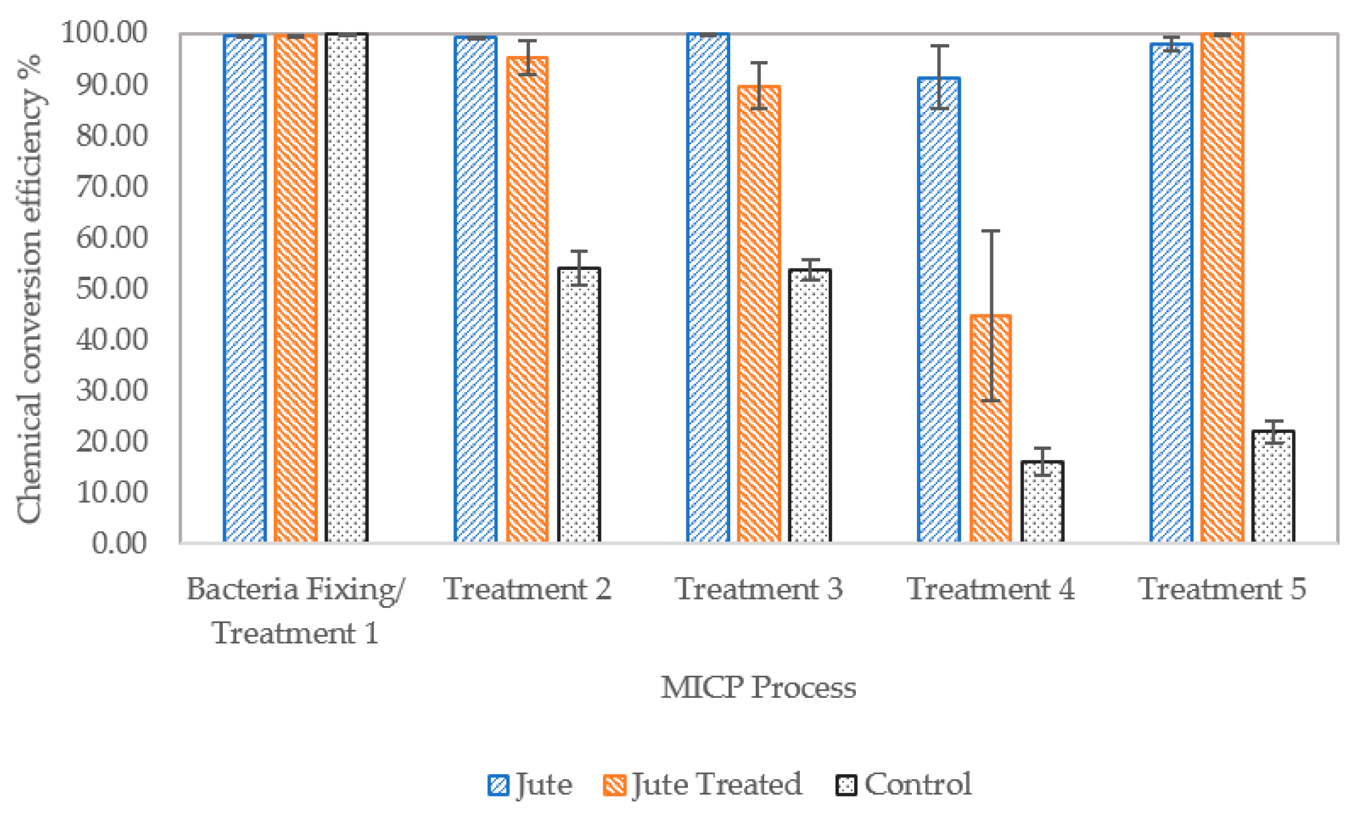
Figure 9.
Chemical conversion efficiency, with error bars showing standard error of means.
Figure 9.
Chemical conversion efficiency, with error bars showing standard error of means.
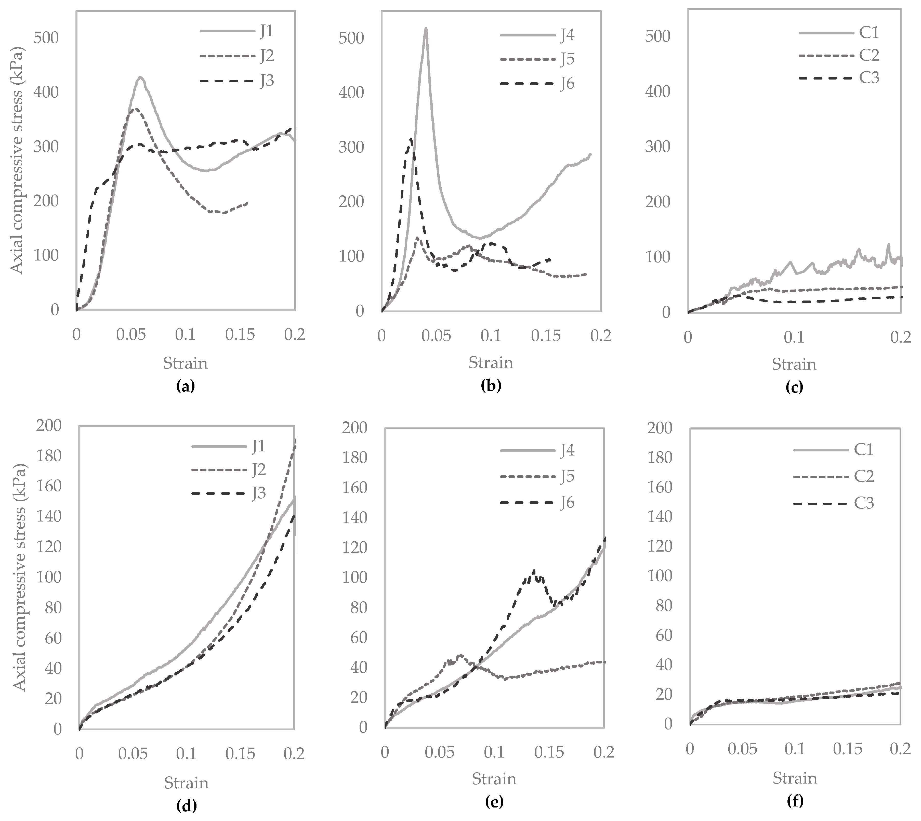
Figure 10.
Unconfined compression test results following CM treatment five (a–c), and after reconstitution, flushing and saturation with water and eight days curing to test for self-healing (d–f).
Figure 10.
Unconfined compression test results following CM treatment five (a–c), and after reconstitution, flushing and saturation with water and eight days curing to test for self-healing (d–f).
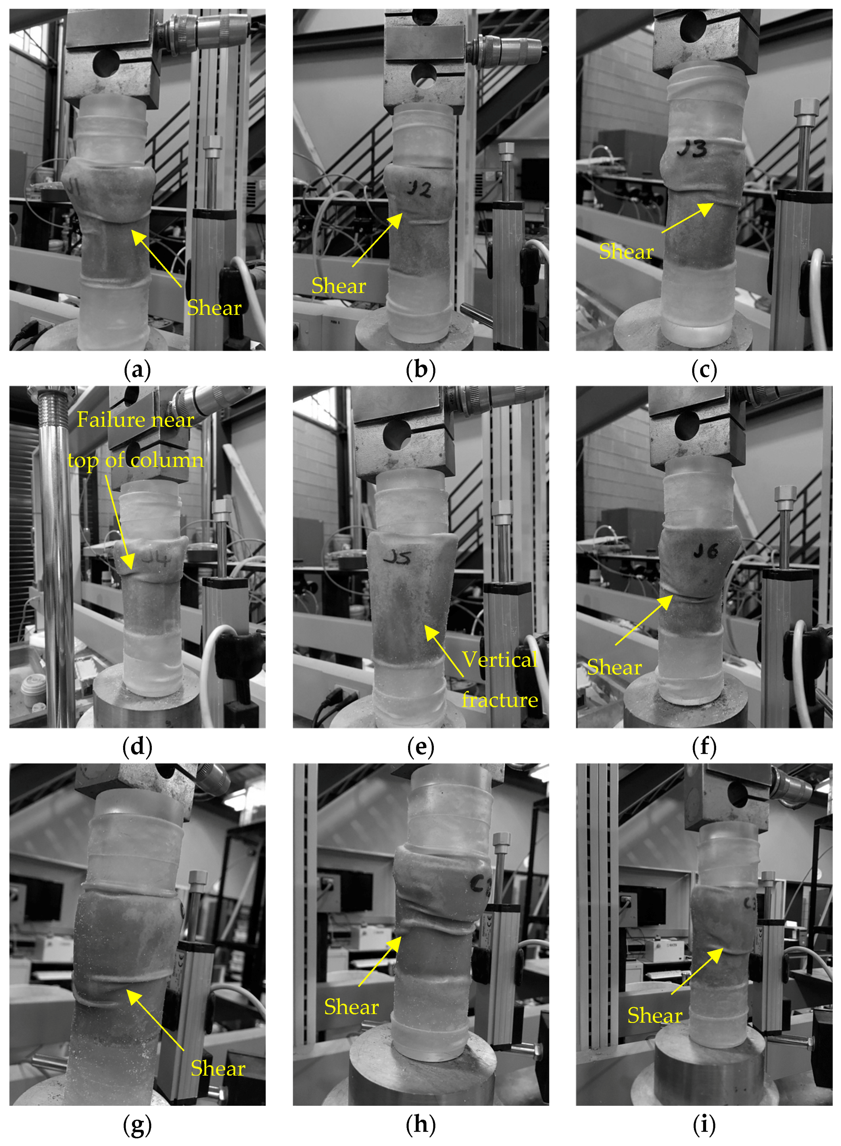
Figure 11.
Images of columns J1 to J3 (a–c), J4 to J6 (d–f) and C1 to C3 (g–i), following the onset of failure during unconfined compressive strength testing.
Figure 11.
Images of columns J1 to J3 (a–c), J4 to J6 (d–f) and C1 to C3 (g–i), following the onset of failure during unconfined compressive strength testing.
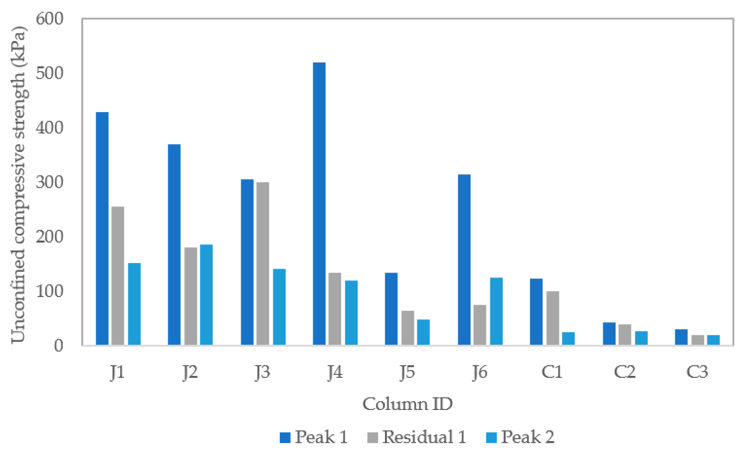
Figure 12.
Unconfined compressive strength (UCS) test results.
Figure 12.
Unconfined compressive strength (UCS) test results.
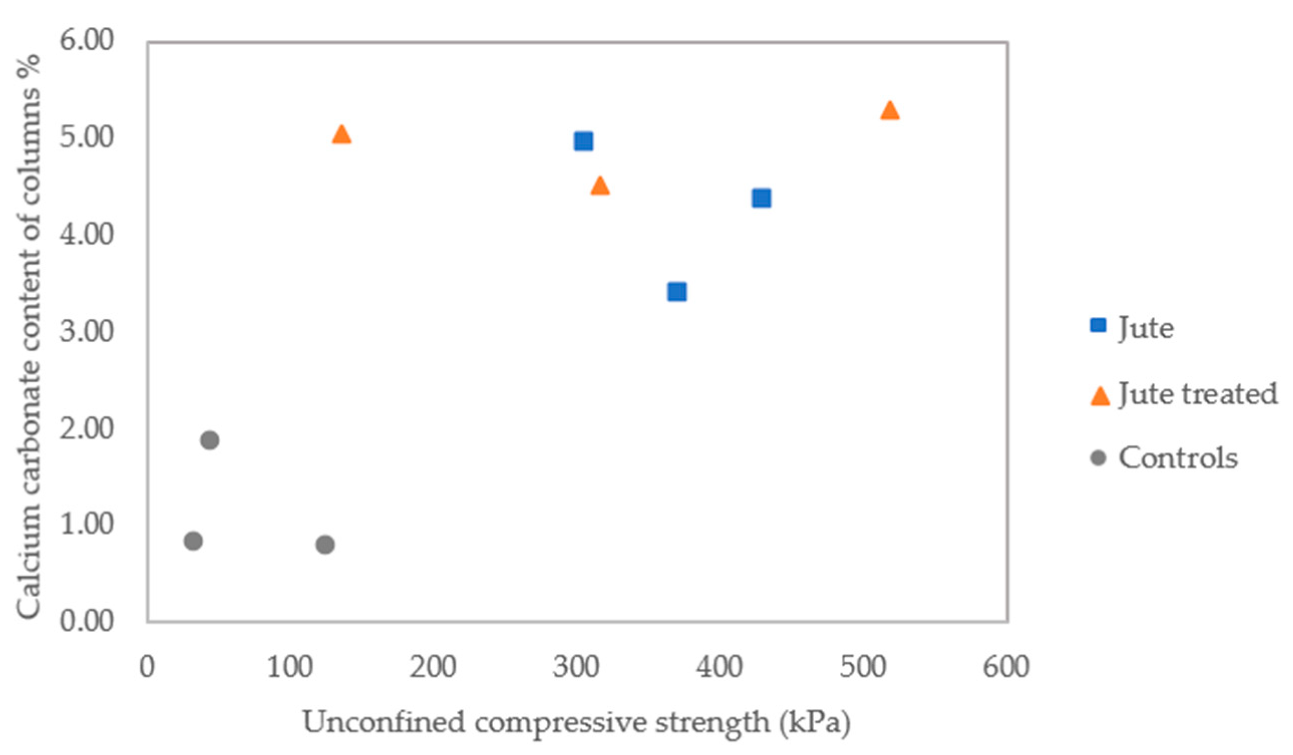
Figure 13.
Calcium carbonate content of columns.
Figure 13.
Calcium carbonate content of columns.
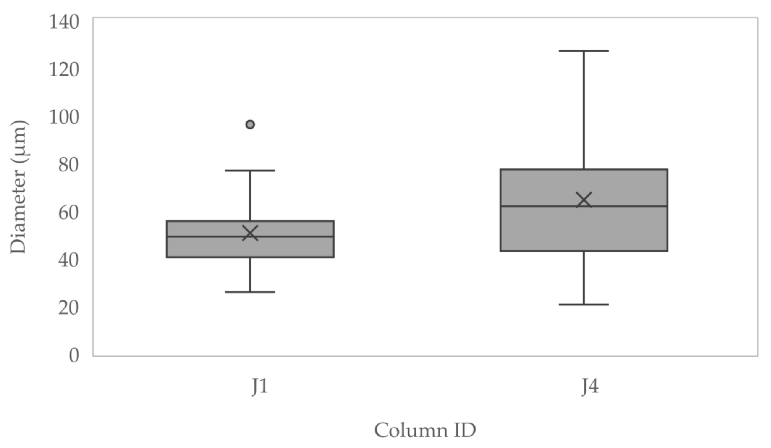
Figure 14.
Diameters of jute fibres measured using scanning electron microscopy (SEM).
Figure 14.
Diameters of jute fibres measured using scanning electron microscopy (SEM).
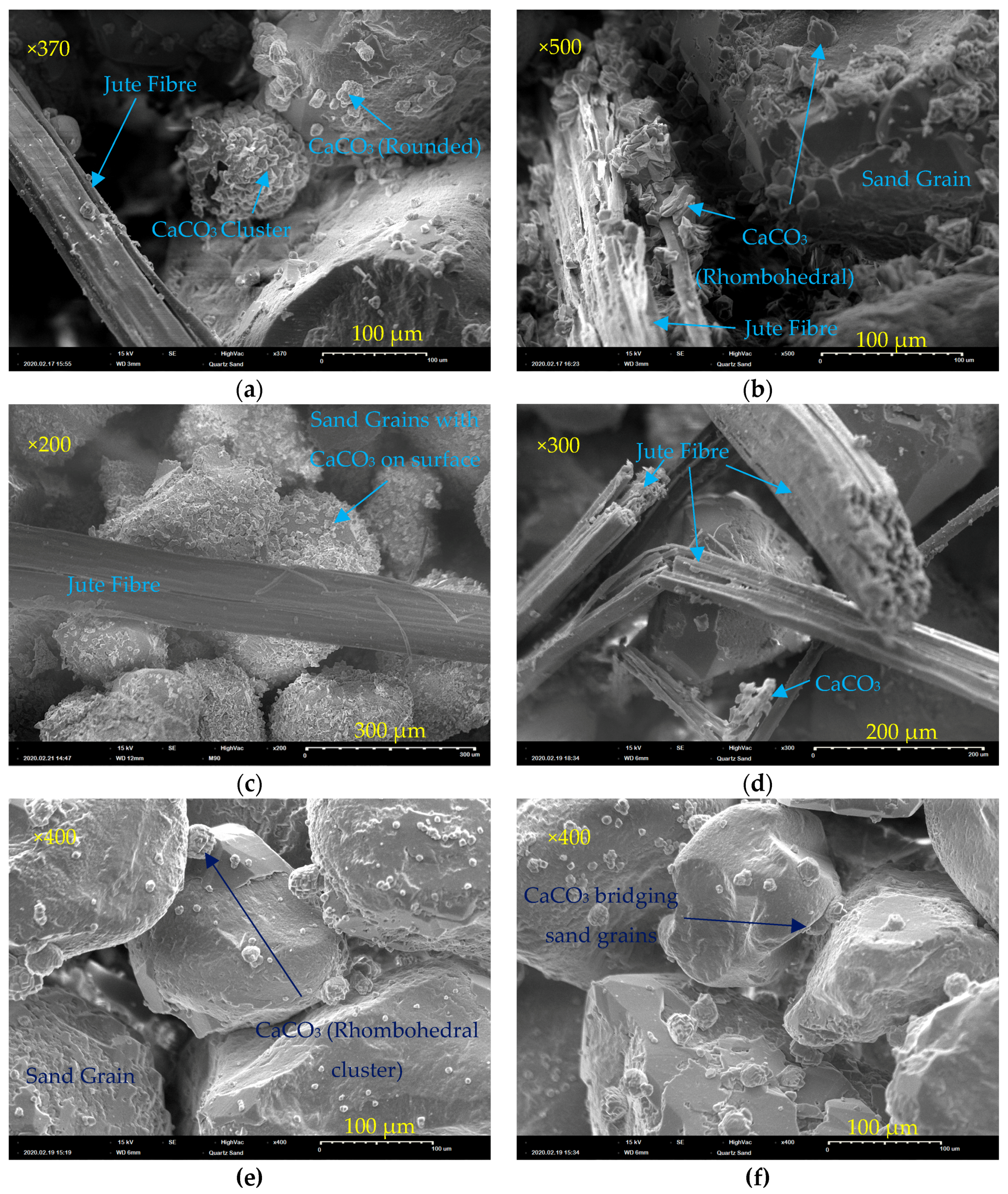
Figure 15.
SEM images of samples from biocemented sand columns containing jute (a,b), treated jute (c,d), and sand only controls (e,f).
Figure 15.
SEM images of samples from biocemented sand columns containing jute (a,b), treated jute (c,d), and sand only controls (e,f).
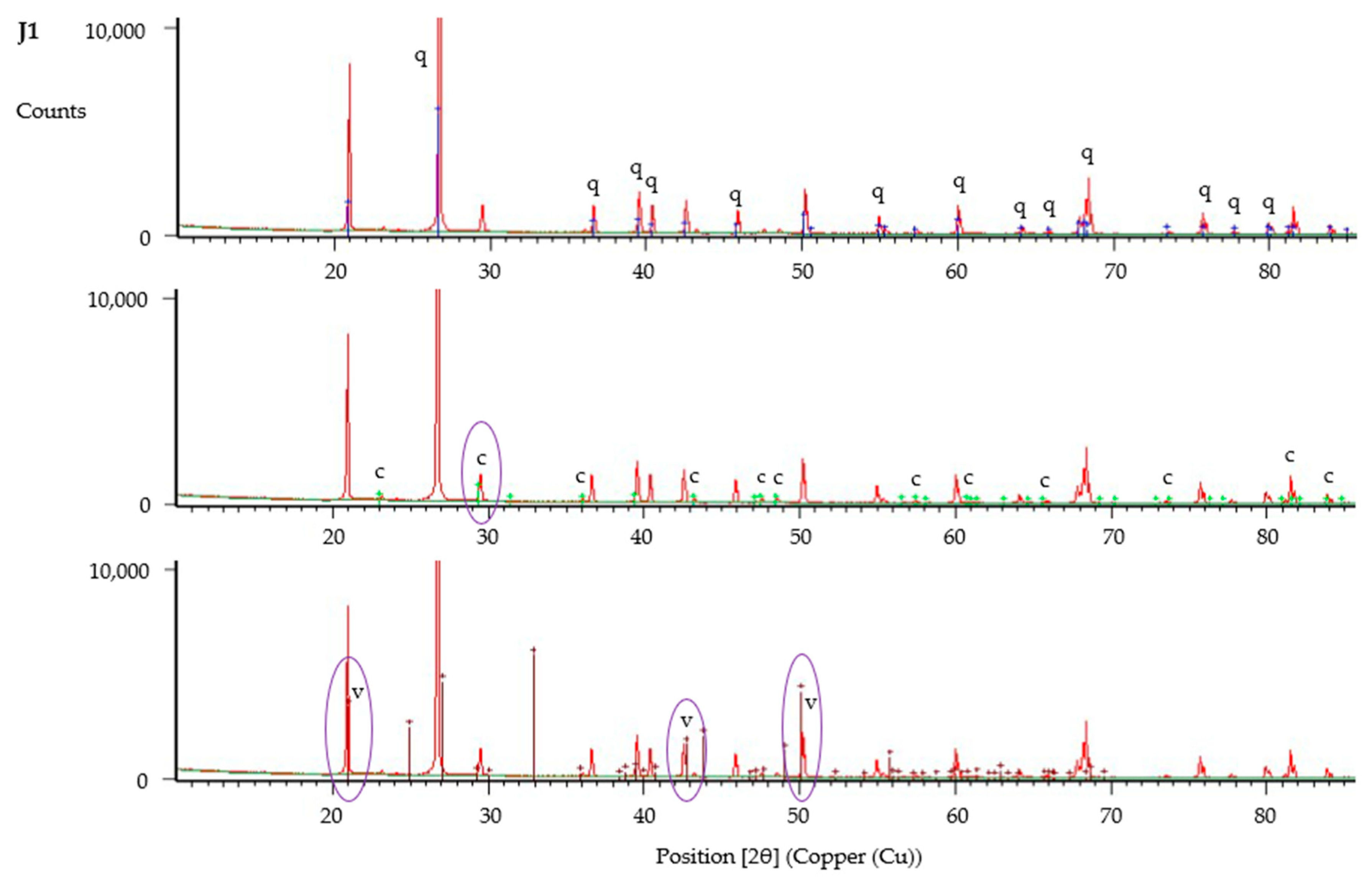
Figure 16.
X-ray powder diffraction (XRD) analysis of sample from column J1, showing identified peaks of quartz (q), calcite (c) and vaterite (v).
Figure 16.
X-ray powder diffraction (XRD) analysis of sample from column J1, showing identified peaks of quartz (q), calcite (c) and vaterite (v).
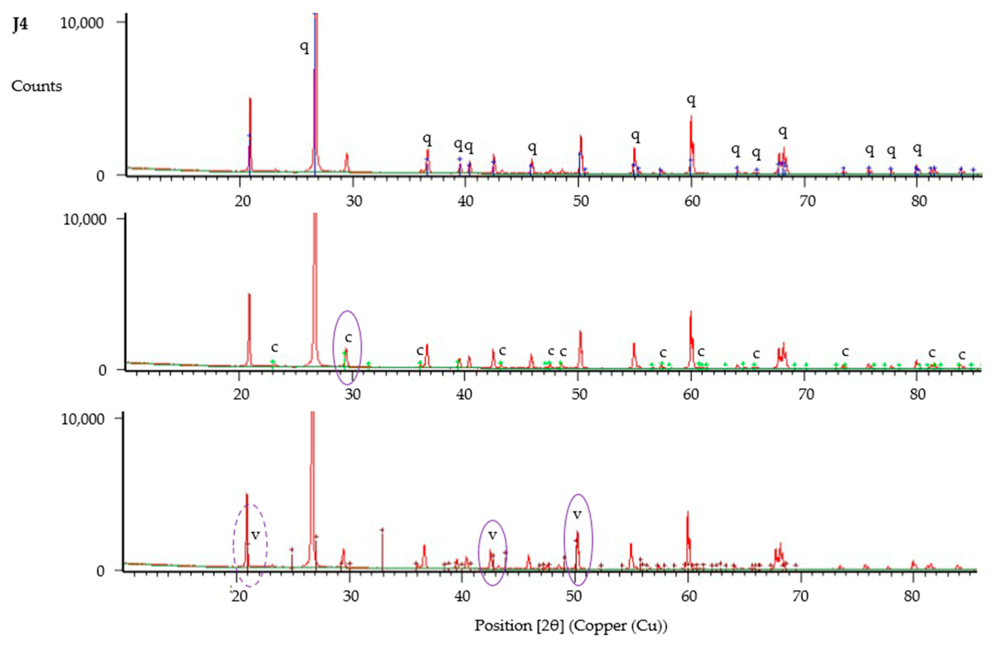
Figure 17.
XRD analysis of sample from column J4, showing identified peaks of quartz (q), calcite (c) and vaterite (v). The peak at 21 [°2θ] is identified as vaterite based on results for J1 and C1, however results for J4 alone suggest this could be also be quartz.
Figure 17.
XRD analysis of sample from column J4, showing identified peaks of quartz (q), calcite (c) and vaterite (v). The peak at 21 [°2θ] is identified as vaterite based on results for J1 and C1, however results for J4 alone suggest this could be also be quartz.
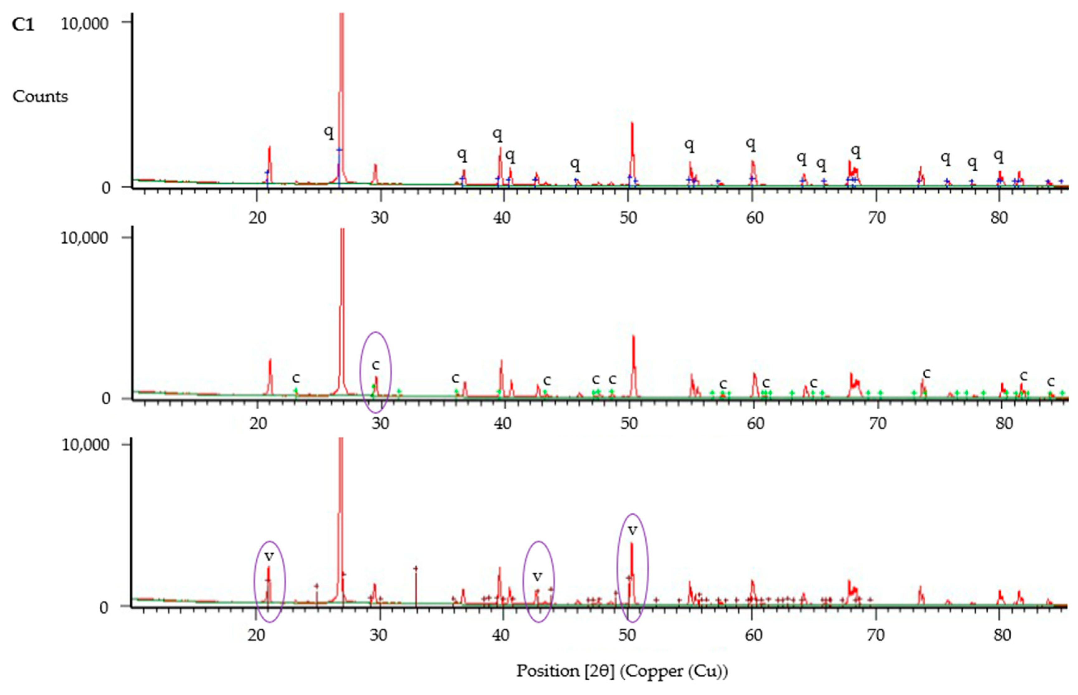
Figure 18.
XRD analysis of sample from column C1, showing identified peaks of quartz (q), calcite (c) and vaterite (v).
Figure 18.
XRD analysis of sample from column C1, showing identified peaks of quartz (q), calcite (c) and vaterite (v).
Table 1.
Sand properties.
Table 1.
Sand properties.
| Soil Origin | Gs | ρ (g/cm3) | Mineralogy | Shape |
|---|
| Ottawa | 2.65 | 1.522 | Quartz | Round |
Table 2.
Cementation media composition and sterilisation methods.
Table 2.
Cementation media composition and sterilisation methods.
| Precursor Chemicals and Nutrients | CM1
(g/L) | CM2
(g/L) | CM3
(g/L) | Sterilisation Method |
|---|
| Calcium chloride dihydrate (CaCl2∙2H2O) | 73.51 | 73.51 | 147.02 | Autoclaved |
| Urea (NH2(CO)NH2) | 40 | 40 | 80 | Syringe filtered |
| Ammonium chloride (NH4Cl) | 0 | 20 | - | Autoclaved |
| Sodium bicarbonate (NaHCO3) | 0 | 2.12 | - | Syringe filtered |
| Oxoid CM0001 nutrient broth | 3 | 6 | 12 | Autoclaved |
Table 3.
Column contents.
Table 3.
Column contents.
| Column ID | Sand, g | Jute, g | Immobilised CM, g |
|---|
| J1 | 133 | 1 | 0 |
| J2 | 133 | 1 | 0 |
| J3 | 133 | 1 | 0 |
| J4 | 133 | 1 | 1.687 |
| J5 | 133 | 1 | 1.681 |
| J6 | 133 | 1 | 1.686 |
| C1 | 143 | 0 | 0 |
| C2 | 143 | 0 | 0 |
| C3 | 143 | 0 | 0 |
Table 4.
Columns treatment schedule.
Table 4.
Columns treatment schedule.
| Day | Time Since Prior Injection (h) | Column Injection (1.5 × Pore Volume) | Treatment |
|---|
| 0 | 0 | CM1 | 1 |
| 1 | 16 | CM2 | 2 |
| 2 | 22 | CM2 | 3 |
| 3 | 24 | CM2 | 4 |
| 4 | 24 | CM2 | 5 |
| 12 | 192 | Tap Water | None |
Table 5.
Results from urease activity tests.
Table 5.
Results from urease activity tests.
| ID | Water | Inoculant | pH | Culture Time | OD | Electrical Conductivity (mS/cm/min) | Urea Hydrolysed (mM/min) | Specific Urease Activity (mM/min/OD) |
|---|
| 1 | Tap | PC | 8.37 | 19 | 0.940 | 0.56 | 6.22 | 6.62 |
| 2 | DI | PC | 7.97 | 19 | 0.937 | 0.41 | 4.59 | 4.90 |
| 3 | Tap | LBC | 8.37 | 19 | 1.308 | 0.75 | 8.30 | 6.34 |
| 4 | Tap | LBC | 8.37 | 16 | 1.222 | 0.69 | 7.63 | 6.24 |
| 5 | Tap | LBC | 8.37 | 14 | 1.068 | 0.57 | 6.30 | 5.89 |
| 6 | DI | LBC | 6.46 | 19 | 1.005 | 0.63 | 6.96 | 6.93 |
| 7 | DI | LBC | 7.15 | 19 | 0.822 | 0.57 | 6.37 | 7.75 |
| 8 | DI | LBC | 7.97 | 19 | 1.038 | 0.55 | 6.15 | 5.92 |
| 9 | DI | LBC | 8.53 | 19 | 1.134 | 0.50 | 5.56 | 4.90 |
| 10 | DI | LBC | 8.86 | 19 | 1.196 | 0.44 | 4.89 | 4.09 |
| 11 | DI | LBC | 9.17 | 19 | 1.156 | 0.41 | 4.59 | 3.97 |
Table 6.
Sand parameters.
Table 6.
Sand parameters.
| D10 | D50 | D60 | D30 | Cu | Cz |
|---|
| 0.140 | 0.226 | 0.250 | 0.193 | 1.786 | 1.064 |
Table 7.
Optical density of column effluent following bacteria fixing.
Table 7.
Optical density of column effluent following bacteria fixing.
| Column | J1 | J2 | J3 | J4 | J5 | J6 | C1 | C2 | C3 |
|---|
| Effluent OD600 (5–10 mL) | 0.018 | 0.01 | 0.015 | 0.011 | 0.008 | 0.011 | 0.055 | 0.02 | 0.044 |
Table 8.
Moisture and CaCO3 contents of biocemented columns (averages from triplicates).
Table 8.
Moisture and CaCO3 contents of biocemented columns (averages from triplicates).
| Columns | Moisture Content % | CaCO3 Content% |
|---|
| J1–J3 | 18.35 ± 0.34 | 3.98 ± 0.59 |
| J4–J6 | 16.82 ± 1.33 | 4.63 ± 0.31 |
| C1–C3 | 17.03 ± 0.39 | 1.08 ± 0.47 |


