Investigations into Structural Behavior of Concrete-Filled RHS Columns with Unequal Flange Thickness under Compressive Load


Abstract
:1. Introduction
2. Experimental Studies
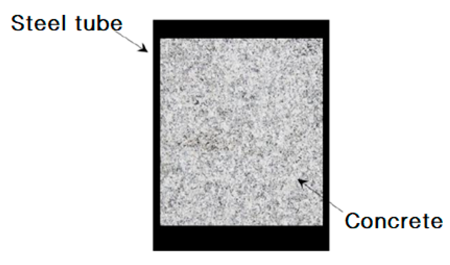
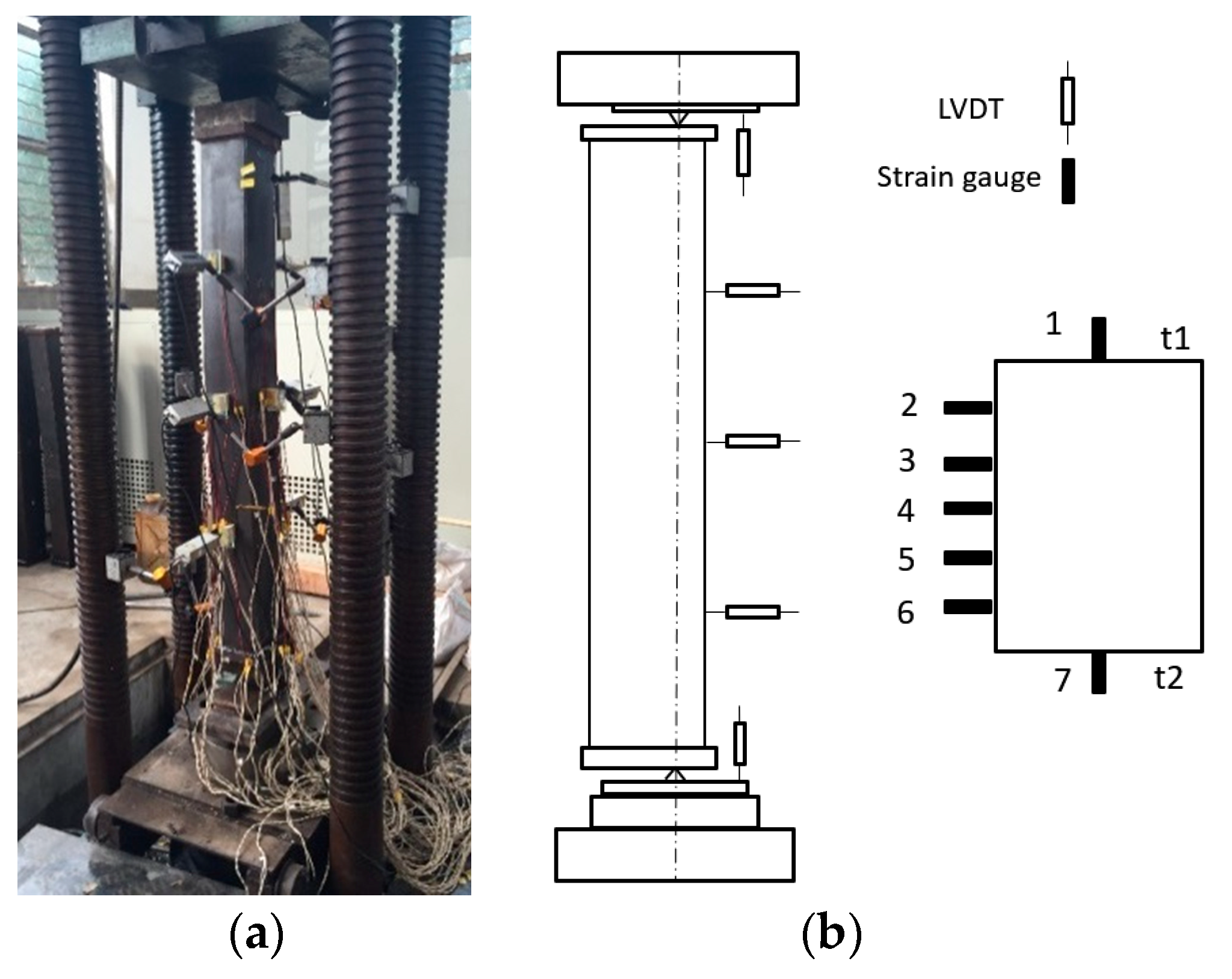
2.1. Test Program
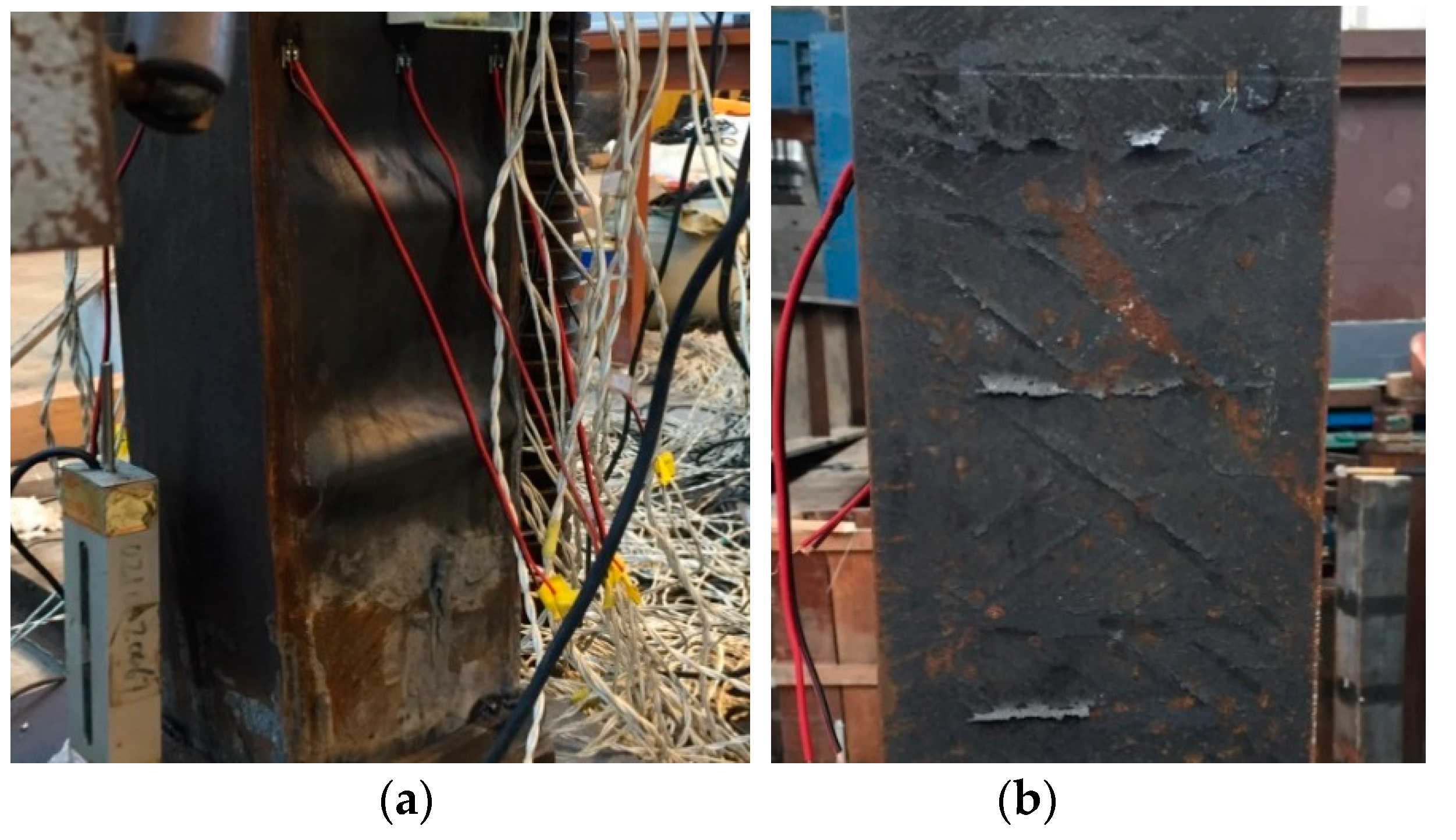
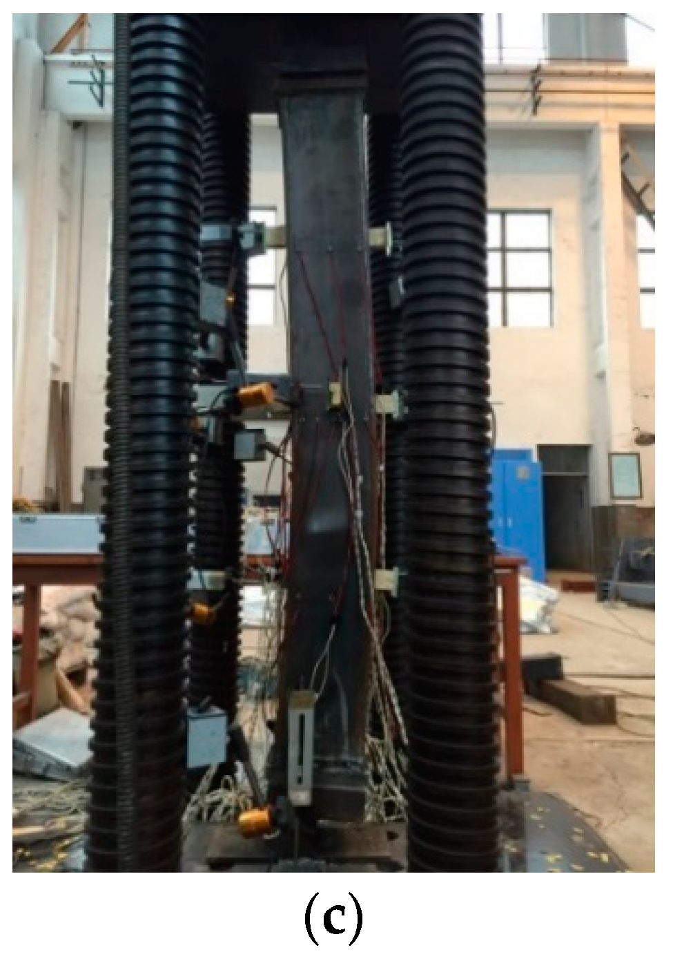
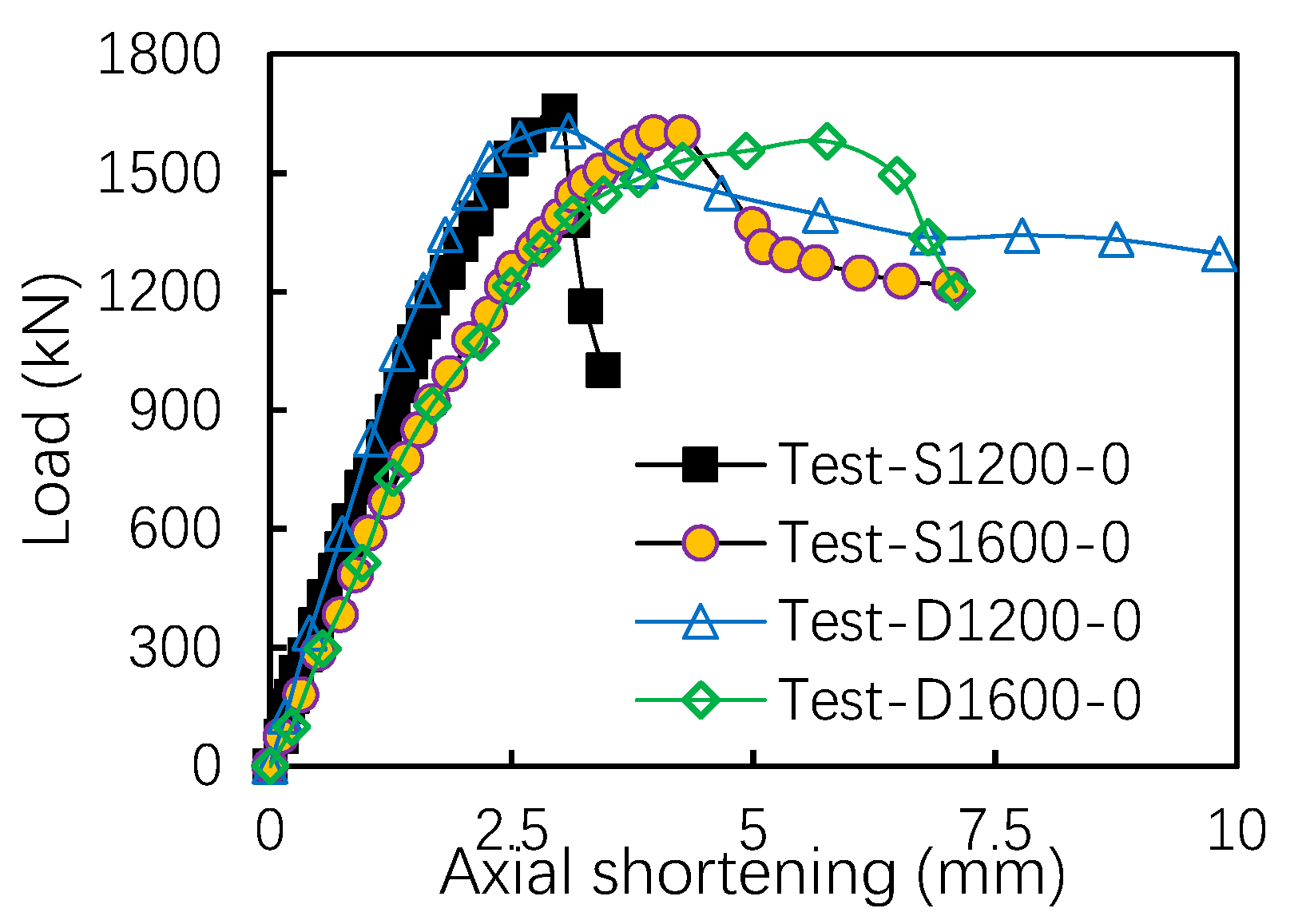
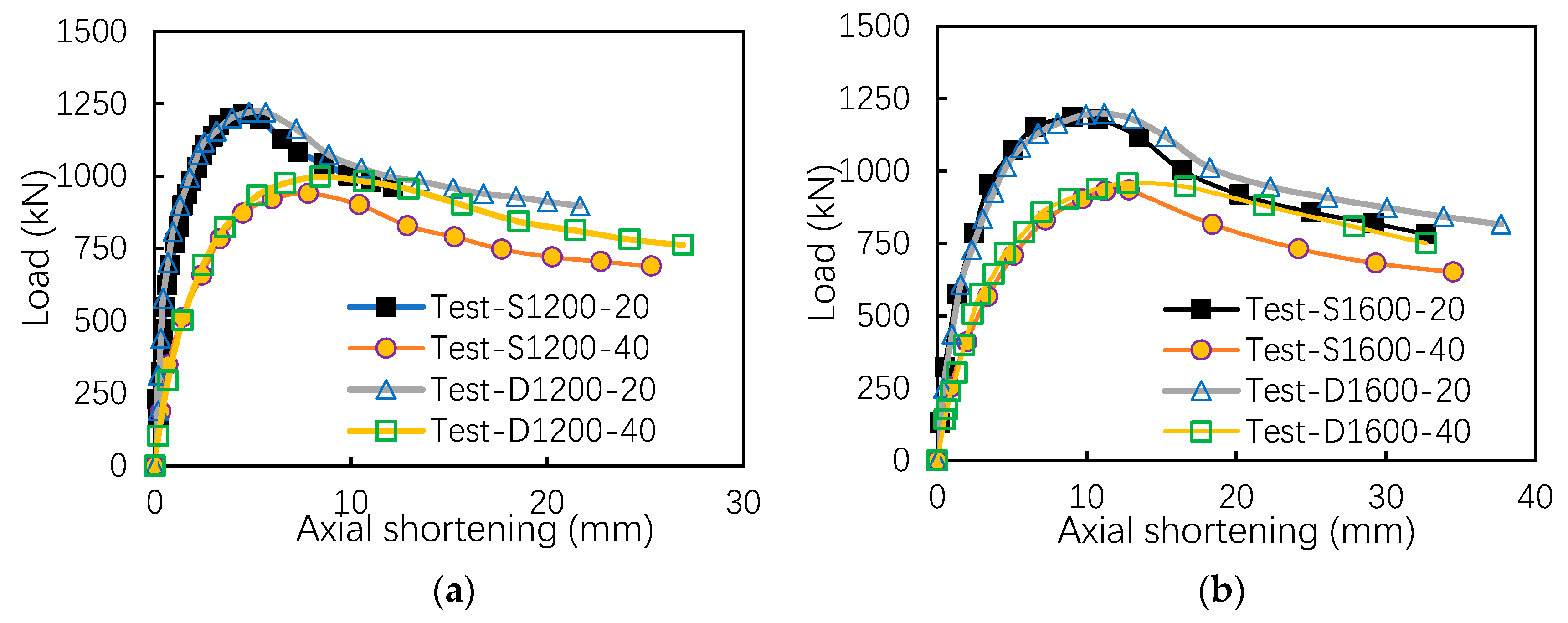
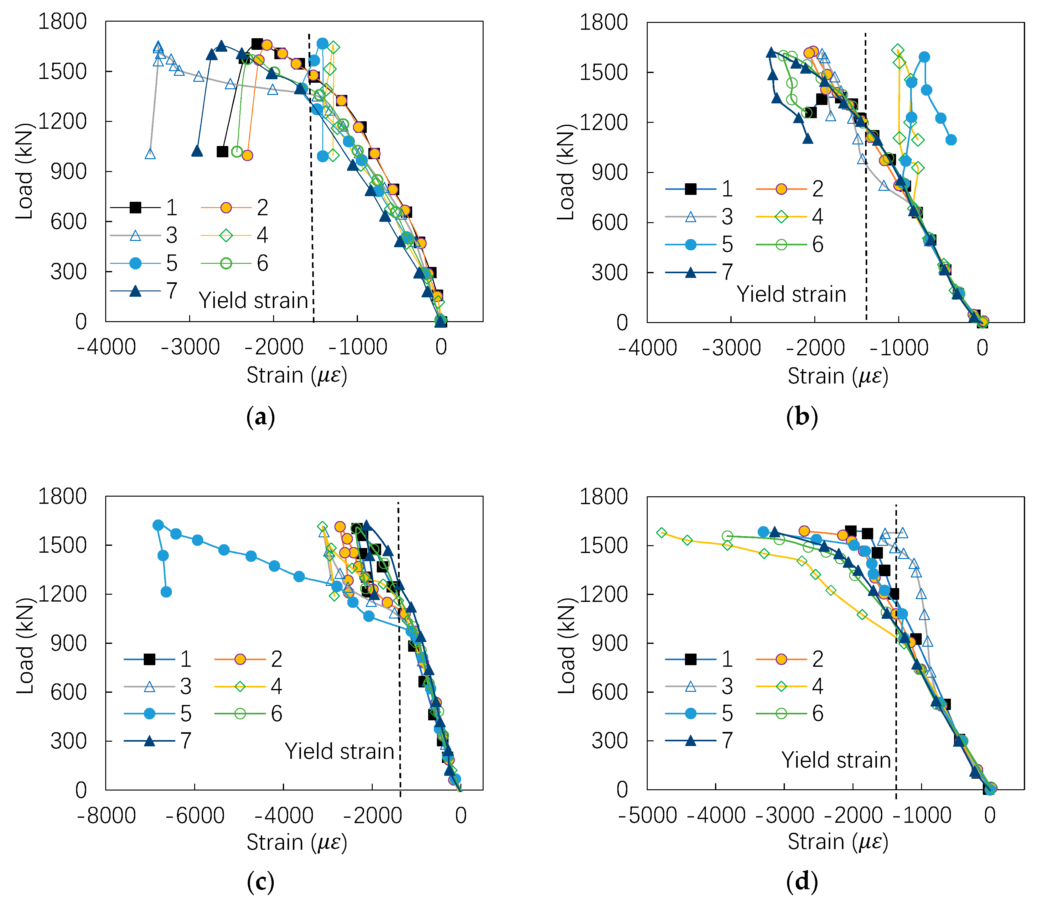
2.2. Test Results
3. Numerical Analysis
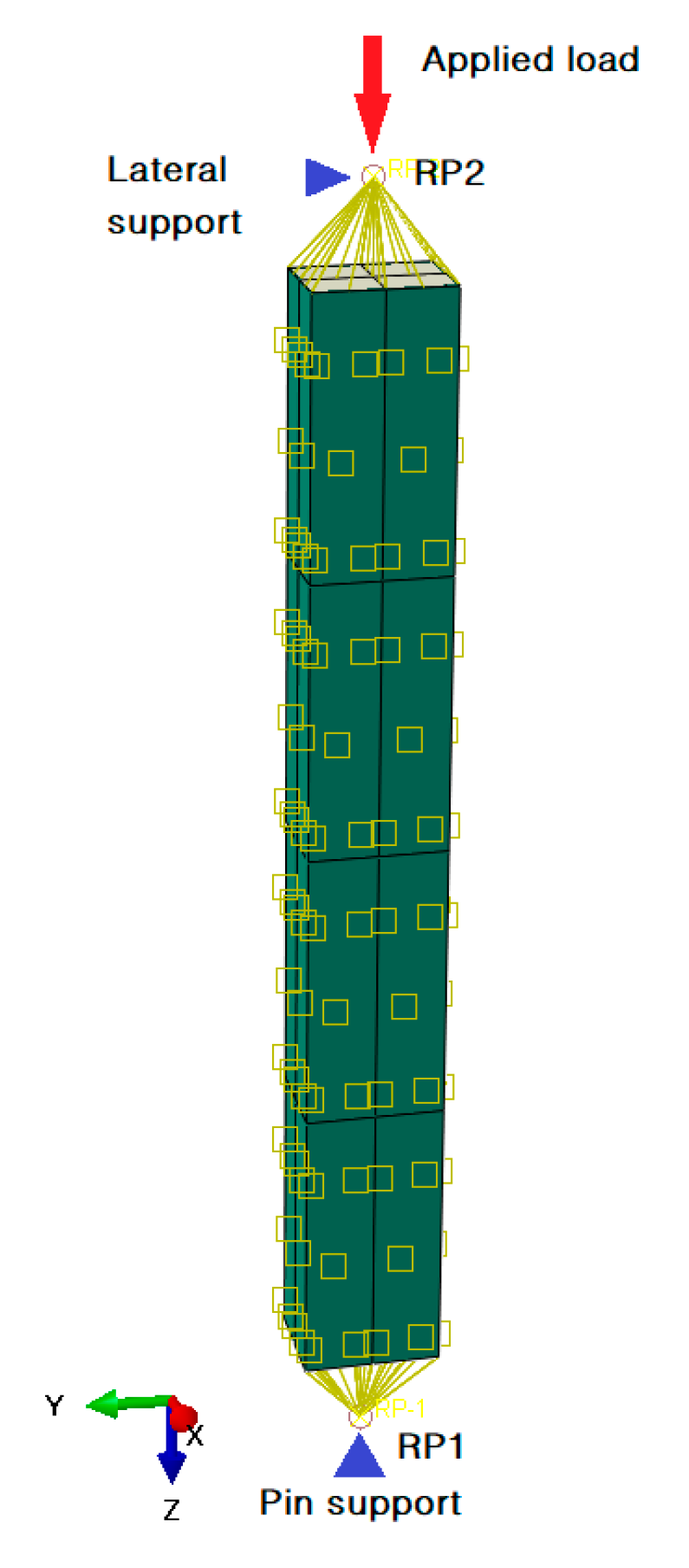
3.1. Modeling Process
3.2. Model Validation
3.3. Parametric Analysis
4. Analytical Design Approach
- (1)
- The lateral effect of the steel column is ignored.
- (2)
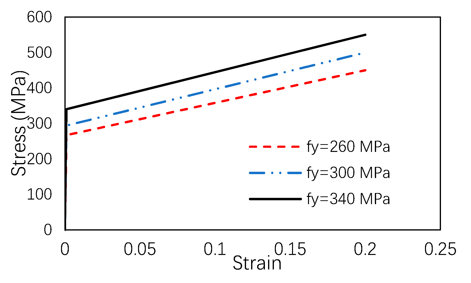
- It is assumed that the stress–strain curve of the steel and concrete is following ideal elastoplasticity.
- (3)
- The deformations of the steel tube and the core concrete are coordinated.
- (4)
- The deflection of the column is assumed as a sine half-wave under the failure load.
4.1. Case Study
Case 1
Case 2
4.2. Results Comparison
5. Conclusions
- (1)
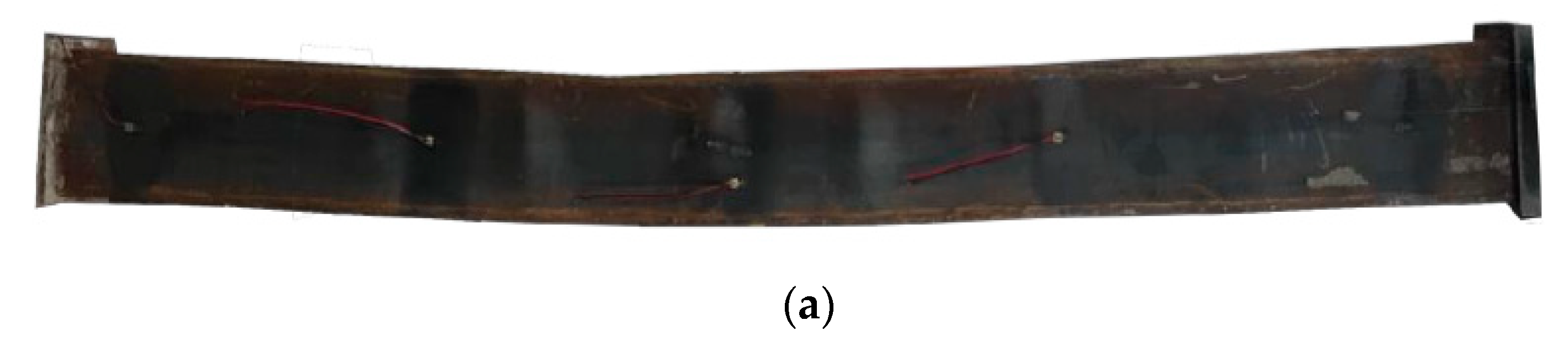
- The failure mode of the axial compression column is the local buckling of the tube on the top side, and the final failure mode of the eccentric compressed column is the buckling on the middle section of the column. For the equal-walled and unequal-walled CFRHS columns, when the thickness of the flange and web is relatively small, the bucking is tending to occur on these regions; hence, the outer steel tube needs to be reinforced to resist local buckling.
- (2)
- It is found that axially compressed unequal-wall-thickness CFRHS columns have good ductility when compared with the unequal-wall-thickness columns.
- (3)
- It is indicated that, with the same section area, slenderness, and eccentricity, the load-bearing capacity of eccentrically compressed CFRHS column with unequal wall thickness can improve 20% more than columns with equal shell thickness. Therefore, in order to improve the load-bearing capacity, we recommend designing the eccentric compressed column with unequal-wall-thickness section.
- (4)
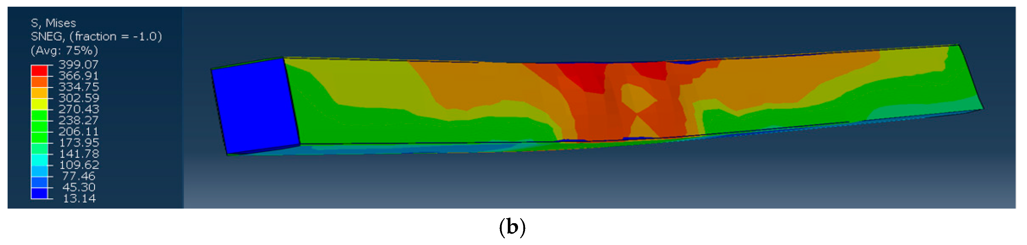
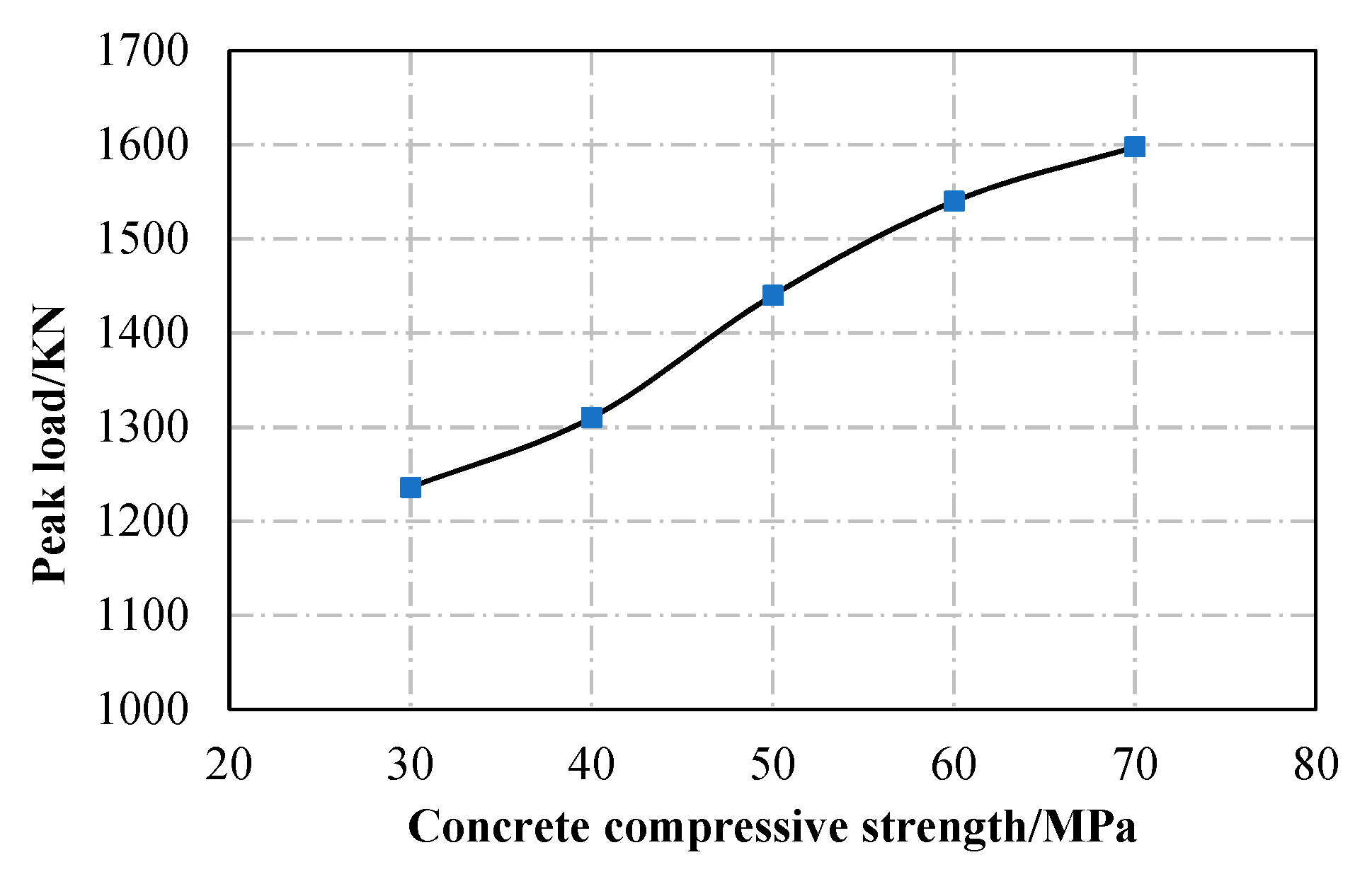
- The numerical simulation method of the compressed CFRHS column is in good agreement with the experimental results, which verifies the correctness of the finite element simulation method. Parametric studies show that the eccentricity, shell thickness, and concrete strength have a significant impact on the load-bearing capacity of the column.
Author Contributions
Funding
Conflicts of Interest
References
- Lu, Y.Q.; Kennedy, D.J.L. The flexural behaviour of concrete-filled hollow structural sections. Can. J. Civ. Eng. 1994, 21, 111–130. [Google Scholar] [CrossRef]
- Jiang, A.Y.; Chen, J.; Jin, W.L. Experimental investigation and design of thin-walled concrete-filled steel tubes subject to bending. Thin Wall. Struct. 2013, 63, 44–50. [Google Scholar] [CrossRef]
- Moon, J.; Roeder, C.W.; Lehman, D.E.; Lee, H.E. Analytical modeling of bending of circular concrete-filled steel tubes. Eng. Struct. 2012, 42, 349–361. [Google Scholar] [CrossRef]
- Han, L.H. Tests on stub columns of concrete-filled RHS sections. J. Constr. Steel Res. 2002, 58, 353–372. [Google Scholar] [CrossRef]
- Lyu, X.T.; Xu, Y.; Xu, Q.; Yu, Y. Axial Compression Performance of Square Thin Walled Concrete-Filled Steel Tube Stub Columns with Reinforcement Stiffener under Constant High-Temperature. Materials 2019, 12, 1098. [Google Scholar] [CrossRef] [PubMed] [Green Version]
- Liu, S.M.; Ding, X.X.; Li, X.K.; Liu, Y.; Zhao, S. Behavior of Rectangular-Sectional Steel Tubular Columns Filled with High-Strength Steel Fiber Reinforced Concrete under Axial Compression. Materials 2019, 12, 2716. [Google Scholar] [CrossRef] [PubMed] [Green Version]
- Cha, S.L.; Lee, J.S.; Park, C.K.; Kim, J.K.; Kwon, S.H. Experimental Investigation on Behavior of Rectangular Concrete-Filled Tubular Columns Considering Diaphragms. Materials 2020, 13, 4412. [Google Scholar] [CrossRef] [PubMed]
- Hasan, H.G.; Ekmekyapar, T.; Shehab, B.A. Mechanical performances of stiffened and reinforced concrete filled steel tubes under axial compression. Mar. Struct. 2019, 65, 417–432. [Google Scholar] [CrossRef]
- Zhang, T.; Ding, F.X.; Liu, X.M.; Yu, Z.W. Compressive behavior of steel-reinforced concrete-filled circular steel tubular stub columns. Structures 2020, 28, 863–877. [Google Scholar] [CrossRef]
- Varma, A.H.; Ricles, J.M.; Sause, R.; Lu, L.W. Seismic Behavior and Modeling of High-Strength Composite Concrete-Filled Tube (CFT) Beam-Columns. J. Constr. Steel Res. 2002, 58, 725–758. [Google Scholar] [CrossRef]
- Johansson, M.; Gyllotoft, K. Mechanical behavior of circular steel-concrete composite stub columns. J. Struct. Eng. 2002, 128, 1073–1081. [Google Scholar] [CrossRef]
- Lu, H.; Han, L.H.; Zhao, X.L. Analytical behavior of circular concrete filled thin-walled steel tubes subjected to bending. Thin Wall. Struct. 2009, 47, 346–358. [Google Scholar] [CrossRef]
- Lu, F.W.; Li, S.P.; Sun, G.J. A study on the behavior of eccentrically compressed square concrete-filled steel tube columns. J. Constr. Steel Res. 2007, 63, 941–948. [Google Scholar] [CrossRef]
- Lim, J.J.; Eom, T.S. Compression tests of octagonal concrete-filled thin-walled tube columns. Eng. Struct. 2020, 221, 111082. [Google Scholar] [CrossRef]
- Lu, F.W.; Li, S.P.; Li, D.W.; Sun, G. Flexural behavior of concrete filled non-uni-thickness walled rectangular steel tube. J. Constr. Steel Res. 2007, 63, 1051–1057. [Google Scholar] [CrossRef]
- Zhang, Y.; Yu, C.J.; Zhao, S.X.; Li, S. Investigation on elastic plastic stage of asymmetric rectangular CFST beams with unequal wall thickness. Int. J. Earth Sci. Eng. 2016, 9, 622–631. [Google Scholar]
- Zhang, Y.; Yu, C.J.; Fu, G.Y.; Chen, B.; Li, S.P. Study on rectangular concrete-filled steel tubes with unequal wall thickness. Steel Compos. Struct. 2016, 22, 1073–1084. [Google Scholar] [CrossRef]
- ABAQUS. Analysis User’s Manual Version 6.12; ABAQUS Inc.: Vélizy-Villacoublay, France, 2012. [Google Scholar]
- Tao, Z.; Wang, Z.B.; Yu, Q. Finite element modelling of concrete-filled steel stub columns under axial compression. J. Constr. Steel Res. 2013, 89, 121–131. [Google Scholar] [CrossRef]
- Zhang, Q.; Fu, L.; Xu, L. An efficient approach for numerical simulation of concrete-filled round-ended steel tubes. J. Constr. Steel Res. 2020, 170, 106086. [Google Scholar] [CrossRef]
- Alatshan, F.; Osman, S.A.; Mashiri, F.; Hamid, R. Explicit Simulation of Circular CFST Stub Columns with External Steel Confinement under Axial Compression. Materials 2020, 13, 23. [Google Scholar] [CrossRef] [Green Version]
- Shin, J.; Hwang, S.H.; Kim, J. Numerical Investigation of Blast Performance of Plate-Reinforced Moment-Resisting Connection Using Large Concrete Filled Tubular Section. Appl. Sci. 2020, 10, 3700. [Google Scholar] [CrossRef]
- Xiamuxi, A.; Liu, X.; Hasegawa, A. Study of the concrete in reinforced concrete-filled steel tube column under axial loading. J. Constr. Steel Res. 2020, 170, 106111. [Google Scholar] [CrossRef]
- Saenz, L.P. Discussion of ‘Equation for the stress–strain curve of concrete’ by P. Desayi, and S. Krishnan. J. Am. Concr. Inst. 1964, 61, 1229–1235. [Google Scholar]
- AISC Committee. Specification for Structural Steel Buildings: ANSI/AISC 360-10; American Institute of Steel Construction: Chicago, IL, USA, 2010. [Google Scholar]


| Specimen | b/mm | h/mm | L/mm | λ | t1/mm | t2/mm | tw/mm | e/mm | fy1/MPa | fy2/MPa | fyw/MPa | fcu/MPa |
|---|---|---|---|---|---|---|---|---|---|---|---|---|
| S1200-0 | 110 | 150 | 1200 | 27.7 | 7.82 | 7.82 | 2.92 | 0 | 267.9 | 267.9 | 340.7 | 69.6 |
| S1200-20 | 110 | 150 | 1200 | 27.7 | 7.82 | 7.82 | 2.92 | 20 | 267.9 | 267.9 | 340.7 | 69.6 |
| S1200-40 | 110 | 150 | 1200 | 27.7 | 7.82 | 7.82 | 2.92 | 40 | 267.9 | 267.9 | 340.7 | 69.6 |
| D1200-0 | 110 | 150 | 1200 | 27.7 | 5.88 | 9.68 | 2.92 | 0 | 294.4 | 263.2 | 340.7 | 69.6 |
| D1200-20 | 110 | 150 | 1200 | 27.7 | 5.88 | 9.68 | 2.92 | 20 | 294.4 | 263.2 | 340.7 | 69.6 |
| D1200-40 | 110 | 150 | 1200 | 27.7 | 5.88 | 9.68 | 2.92 | 40 | 294.4 | 263.2 | 340.7 | 69.6 |
| S1600-0 | 110 | 150 | 1600 | 37.0 | 7.82 | 7.82 | 2.92 | 0 | 267.9 | 267.9 | 340.7 | 69.6 |
| S1600-20 | 110 | 150 | 1600 | 37.0 | 7.82 | 7.82 | 2.92 | 20 | 267.9 | 267.9 | 340.7 | 69.6 |
| S1600-40 | 110 | 150 | 1600 | 37.0 | 7.82 | 7.82 | 2.92 | 40 | 267.9 | 267.9 | 340.7 | 69.6 |
| D1600-0 | 110 | 150 | 1600 | 37.0 | 5.88 | 9.68 | 2.92 | 0 | 294.4 | 263.2 | 340.7 | 69.6 |
| D1600-20 | 110 | 150 | 1600 | 37.0 | 5.88 | 9.68 | 2.92 | 20 | 294.4 | 263.2 | 340.7 | 69.6 |
| D1600-40 | 110 | 150 | 1600 | 37.0 | 5.88 | 9.68 | 2.92 | 40 | 294.4 | 263.2 | 340.7 | 69.6 |
| Specimen | Nue/kN | Nu-FEM/kN | Nu-FEM/Nue |
|---|---|---|---|
| S1200-0 | 1655 | 1657 | 1.001 |
| S1200-20 | 1215.5 | 1217 | 1.001 |
| S1200-40 | 939.5 | 938 | 0.998 |
| D1200-0 | 1610 | 1600 | 0.994 |
| D1200-20 | 1223 | 1205 | 0.985 |
| D1200-40 | 995 | 896 | 0.901 |
| S1600-0 | 1660.5 | 1636 | 0.985 |
| S1600-20 | 1187.5 | 1154 | 0.972 |
| S1600-40 | 936.5 | 835 | 0.892 |
| D1600-0 | 1580 | 1602 | 1.014 |
| D1600-20 | 1196.5 | 1260 | 1.053 |
| D1600-40 | 953.5 | 978 | 1.026 |
| Mean | 0.985 | ||
| SD | 0.047 |
| Specimen | t2/t1 | λ | NTest/kN | NAnalytical/kN | NAISC/kN | NAnalytical/NTest | NAISC/NTest | Case Type |
|---|---|---|---|---|---|---|---|---|
| S1200-20 | 1.00 | 27.7 | 1215.5 | 1172 | 1315 | 0.964 | 1.082 | 1 |
| S1200-40 | 1.00 | 27.7 | 939.5 | 933 | 1060 | 0.993 | 1.128 | 2 |
| D1200-20 | 1.65 | 27.7 | 1223 | 1208 | 1335 | 0.988 | 1.092 | 1 |
| D1200-40 | 1.65 | 27.7 | 995 | 954 | 1120 | 0.959 | 1.126 | 2 |
| S1600-20 | 1.00 | 37 | 1187.5 | 1128 | 1304 | 0.950 | 1.098 | 1 |
| S1600-40 | 1.00 | 37 | 936.5 | 889 | 1040 | 0.949 | 1.111 | 2 |
| D1600-20 | 1.65 | 37 | 1196.5 | 1166 | 1325 | 0.975 | 1.107 | 1 |
| D1600-40 | 1.65 | 37 | 953.5 | 909 | 1130 | 0.953 | 1.185 | 2 |
| Mean | 0.966 | 1.116 | ||||||
| SD | 0.017 | 0.032 |
Publisher’s Note: MDPI stays neutral with regard to jurisdictional claims in published maps and institutional affiliations. |
© 2020 by the authors. Licensee MDPI, Basel, Switzerland. This article is an open access article distributed under the terms and conditions of the Creative Commons Attribution (CC BY) license (http://creativecommons.org/licenses/by/4.0/).
Share and Cite
Fu, G.; Fu, G.; Li, S.; Yang, J.; Wang, F. Investigations into Structural Behavior of Concrete-Filled RHS Columns with Unequal Flange Thickness under Compressive Load. Materials 2020, 13, 5463. https://doi.org/10.3390/ma13235463
Fu G, Fu G, Li S, Yang J, Wang F. Investigations into Structural Behavior of Concrete-Filled RHS Columns with Unequal Flange Thickness under Compressive Load. Materials. 2020; 13(23):5463. https://doi.org/10.3390/ma13235463
Chicago/Turabian StyleFu, Guangyuan, Gongyi Fu, Siping Li, Jian Yang, and Feiliang Wang. 2020. "Investigations into Structural Behavior of Concrete-Filled RHS Columns with Unequal Flange Thickness under Compressive Load" Materials 13, no. 23: 5463. https://doi.org/10.3390/ma13235463