Analytical Evaluation of the Dendritic Structure Parameters and Crystallization Rate of Laser-Deposited Cu-Fe Functionally Graded Materials


Abstract
:1. Introduction
1.1. Ni-Based FGMs
1.2. Ti-Based FGMs
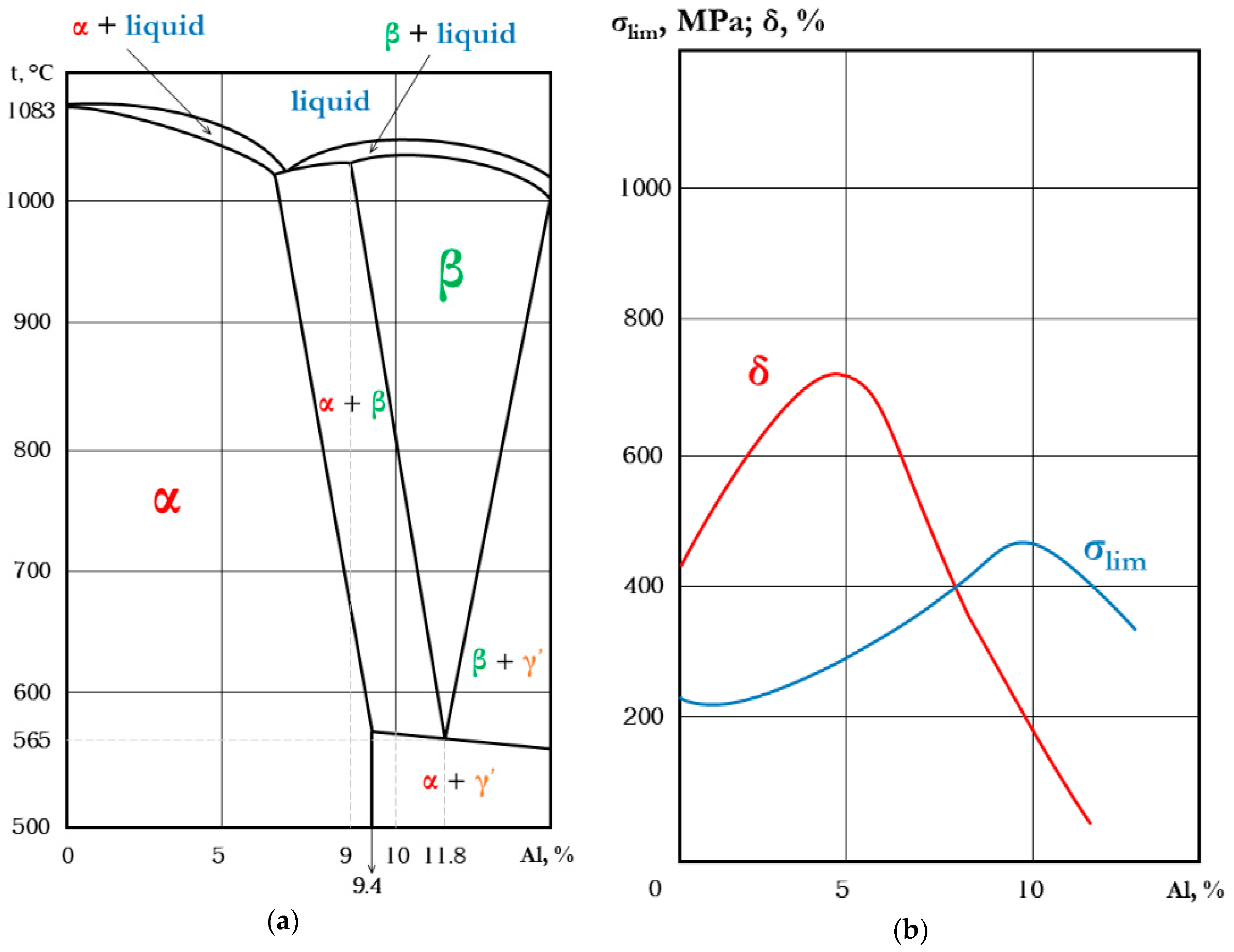
1.3. Al-Based FGMs
1.4. Fe-Based FGMs
1.5. Cr-Based FGMs
1.6. Cu-Based FGMs
2. Materials and Methods
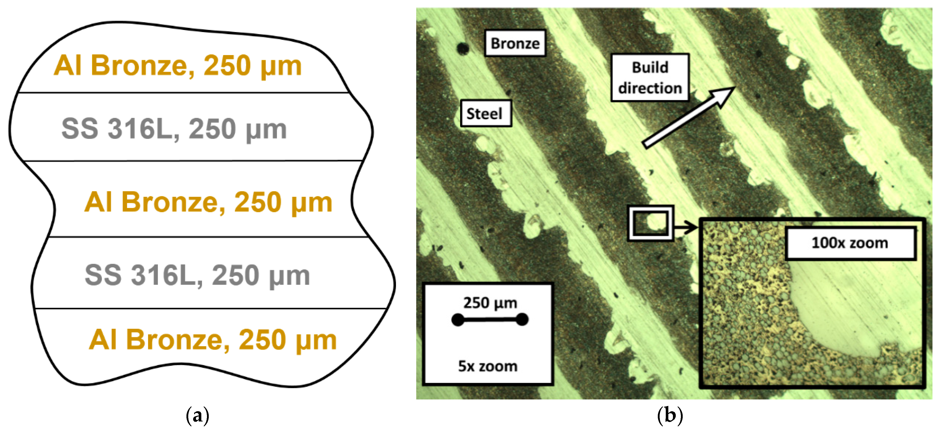
2.1. Materials, Their Characteristics and Process Parameters
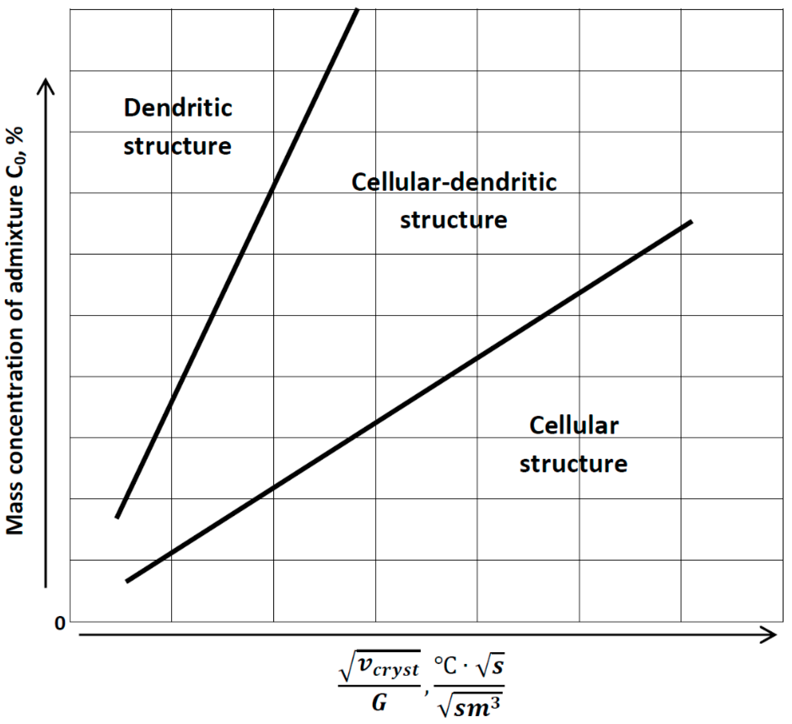
2.2. Relevant Theory. Factors of Dendritic Structure Forming
2.3. Relevant Theory. The Diffusion of Elements through the Moving Phase Interface during the Crystallization Process and the Width of the Secondary Elements of Dendrites
- Diffusion of dissolved matter in solid phase is insignificant;
- Convection and non-diffuse mixing in liquid is important or insignificant;
- The admixture distribution constant k is invariable.
2.4. Relevant Theory. The Crystallization Rate
3. Results
4. Discussion
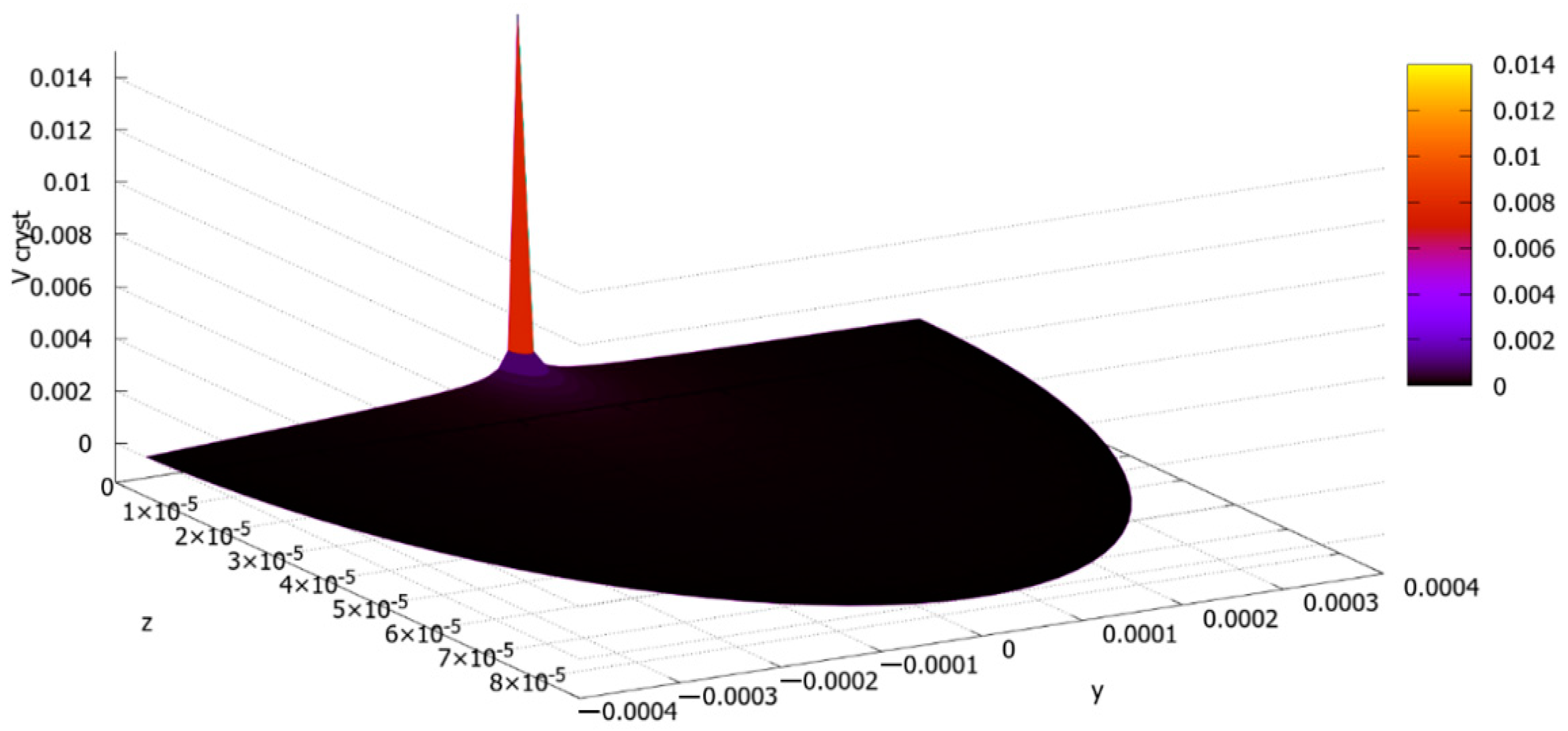
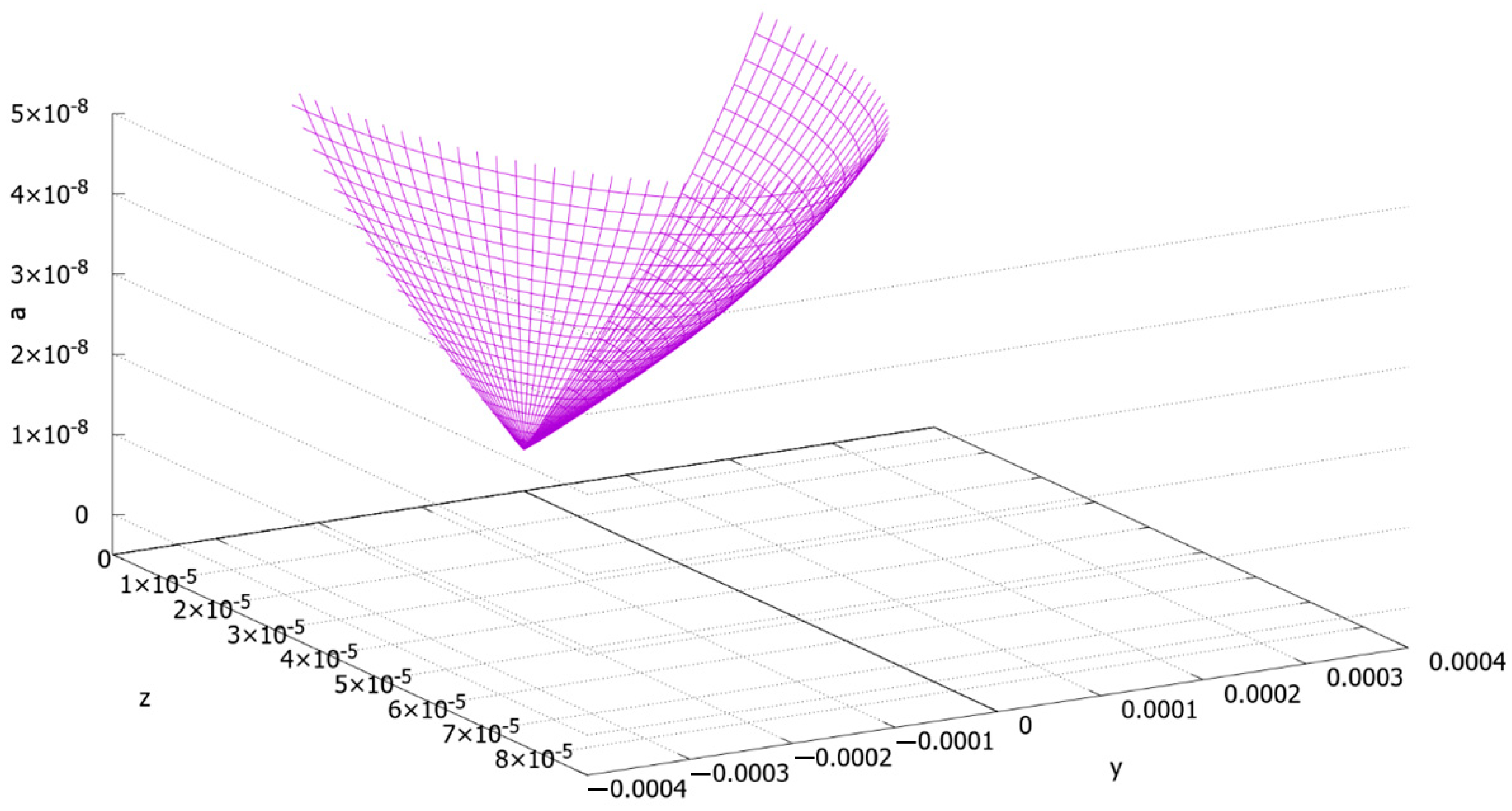
The Final Calculations and Their Discussion
5. Conclusions
Author Contributions
Funding
Acknowledgments
Conflicts of Interest
Appendix A
References
- Watanabe, Y.; Sato, H. Review fabrication of functionally graded materials under a centrifugal force. In Nanocomposites with Unique Properties and Applications in Medicine and Industry; InTechOpen: London, UK, 2011; pp. 133–150. [Google Scholar]
- Singh, R.; Bhavar, V.; Kattire, P.; Thakare, S.; Patil, S.; Singh, R.K.P. A Review on Functionally Gradient Materials (FGMs) and Their Applications. Mater. Sci. Eng. 2017, 229, 012021. [Google Scholar]
- Shishkovsky, I.V. Synthesis of functional gradient parts via RP methods. Rapid Prototyp. J. 2001, 4, 207–211. [Google Scholar] [CrossRef]
- Saleh, B.; Jiang, J.; Fathi, R.; Al-hababi, T.; Xu, Q.; Wang, L.; Song, D.; Ma, A. 30 Years of functionally graded materials: An overview of manufacturing methods, Applications and Future Challenges. Compos. Part B 2020, 201, 108376. [Google Scholar] [CrossRef]
- Mahamood, M.R.; Akinlabi, E.T.; Shukla, M.; Pityana, S. Functionally Graded Material: An Overview. In Proceedings of the World Congress on Engineering 2012, London, UK, 4–6 July 2012; Volume III, pp. 1593–1597. [Google Scholar]
- Udupa, G.; Rao, S.S.; Gangadharan, K.V. Functionally graded Composite materials: An overview. Proc. Mater. Sci. 2014, 5, 1291–1299. [Google Scholar] [CrossRef]
- Richter, V. Fabrication and properties of gradient hard metals. In Proceedings of the 3rd International Symposium on Structural and Functional Gradient Materials (FGM’94), Lausanne, Switzerland, 10–12 October 1994; pp. 587–592. [Google Scholar]
- Wołosz, P.; Baran, A.; Polański, M. The influence of laser engineered net shaping (LENSTM) technological parameters on the laser deposition efficiency and properties of H13 (AISI) steel. J. Alloys Compd. 2020, 823, 153840. [Google Scholar] [CrossRef]
- Sahasrabudhe, H.; Harrison, R.; Carpenter, C.; Bandyopadhyay, A. Stainless steel to titanium bimetallic structure using LENSTM. Addit. Manuf. 2015, 5, 1–8. [Google Scholar]
- Doubenskaia, M.; Kulish, A.; Sova, A.; Petrovskiy, P.; Smurov, I. Experimental and numerical study of gas-powder flux in coaxial laser cladding nozzles of Precitec. Surf. Coat. Technol. 2020, 126672. [Google Scholar] [CrossRef]
- Articek, U.; Milfelner, M.; Anzel, I. Synthesis of functionally graded material H13/Cu by LENS technology. Adv. Prod. Eng. Manag. 2013, 8, 169–176. [Google Scholar] [CrossRef]
- Moharana, B.R.; Sahu, S.K.; Maiti, A.; Sahoo, S.K.; Moharana, T.K. An experimental study on joining of AISI 304 SS to Cu by Nd-YAG laser welding process. Mater. Today Proc. 2020. [Google Scholar] [CrossRef]
- Tan, C.; Zhou, K.; Ma, W.; Min, L. Interfacial characteristics and mechanical performance of maraging steel-copper functional bimetal produced by selective laser melting based hybrid manufacture. Mater. Des. 2018, 155, 77–85. [Google Scholar] [CrossRef]
- Onuike, B.; Heer, B.; Bandyopadhyay, A. Additive manufacturing of Inconel 718-copper alloy bimetallic structure using laser engineered net shaping (LENSTM). Addit. Manuf. 2018, 21, 133–140. [Google Scholar]
- Karnati, S.; Sparks, T.E.; Liou, F.; Newkirk, J.W.; Taminger, K.M.B.; Seufzer, W.J. Laser metal deposition of functionally gradient materials from elemental copper and nickel powders. In Proceedings of the 26th Solid Freeform Fabrication Symposium, Austin, TX, USA, 10–12 August 2015; Bourell, D.L., Ed.; The University of Texas: Austin, TX, USA, 2015; pp. 789–802. [Google Scholar]
- Shakerin, S.; Sanjari, M.; Amirkhiz, B.S.; Mohammadi, M. Interface engineering of additively manufactured maraging steel-H13 bimetallic structures. Mater. Charact. 2020, 170, 110728. [Google Scholar] [CrossRef]
- Shishkovsky, I.; Kakovkina, N.; Missemer, F. Three-dimensional (3-D) laser cladding of functionally graded structures in Ni-Cr-Al system. Laser Eng. 2016, 33, 1–15. [Google Scholar]
- Vilar, R.; Santos, E.C.; Ferreira, P.N.; Franco, N.; da Silva, R.C. Structure of NiCrAlY coatings deposited on single-crystal alloy turbine blade material by laser cladding. Acta Mater. 2009, 57, 5292–5302. [Google Scholar] [CrossRef]
- Banait, S.M.; Paul, C.P.; Jinoop, A.N.; Kumar, H.; Pawade, R.S.; Bindra, K.S. Experimental investigation on laser directed energy deposition of functionally graded layers of Ni-Cr-B-Si and SS316L. Opt. Laser Technol. 2020, 121, 105787. [Google Scholar] [CrossRef]
- Amado, J.M.; Montero, J.; Tobar, M.J.; Yáñez, A. Ni-based metal matrix composite functionally graded coatings. Phys. Proc. 2012, 39, 362–367. [Google Scholar] [CrossRef] [Green Version]
- Balla, V.K.; DeVasConCellos, P.D.; Xue, W.; Bose, S.; Bandyopadhyay, A. Fabrication of compositionally and structurally graded Ti-TiO2 structures using laser engineered net shaping (LENS). Acta Biomater. 2009, 5, 1831–1837. [Google Scholar] [CrossRef]
- Shishkovsky, I.; Missemer, F.; Smurov, I. Direct metal deposition of functional graded structures in Ti-Al system. Phys. Proc. 2012, 39, 382–391. [Google Scholar] [CrossRef] [Green Version]
- Srivastava, D.; Chang, I.T.H.; Loretto, M.H. The effect of process parameters and heat treatment on the microstructure of direct laser fabricated TiAl alloy samples. Intermetallics 2001, 9, 1003–1013. [Google Scholar] [CrossRef]
- Liu, W.; DuPont, J.N. Fabrication of titanium aluminide matrix composites by laser engineered net shaping. Metall. Mater. Transact. A 2004, 35, 1133–1140. [Google Scholar]
- Pimenova, N.V.; Starr, T.L. Electromechanical and corrosion behavior of TixAlyFe alloys prepared by direct metal deposition method. Electromech. Acta 2006, 51, 2042–2049. [Google Scholar] [CrossRef]
- He, X.; Han, J.; Zhang, X. Preparation and ablating behaviour of FGM used in a heat flux rocket engine. In Proceedings of the 34th COSPAR Scientific Assembly of the 2nd World Space Congress, Houston, TX, USA, 10–19 October 2002; NASA Astrophysics Data System: Cambridge, MA, USA, 2002. [Google Scholar]
- Moussa, A.A.; Yadav, R. Optimization of a functionally graded material stem in the femoral component of a cemented hip arthroplasty: Influence of dimensionality of FGM. J. Med. Eng. 2017, 4, 3069351. [Google Scholar]
- Pei, Y.T.; De Hosson, J.T.M. Functionally graded materials produced by laser cladding. Acta Mater. 2000, 48, 2617–2624. [Google Scholar] [CrossRef] [Green Version]
- Pęska, M.; Karczewski, K.; Rzeszotarska, M.; Polański, M. Direct synthesis of Fe-Al alloys from elemental powders using laser engineered net shaping. Materials 2020, 13, 531. [Google Scholar] [CrossRef] [Green Version]
- Łyszkowski, R. High-temperature oxidation of Fe3Al intermetallic alloy prepared by additive manufacturing LENS. Materials 2015, 8, 1499–1512. [Google Scholar] [CrossRef] [Green Version]
- Novák, P.; Zelinková, M.; Šerák, J.; Michalcová, A.; Novák, M.; Vojtěch, D. Oxidation resistance of SHS Fe-Al-Si alloys at 800 °C in air. Intermetallics 2011, 19, 1306–1312. [Google Scholar] [CrossRef]
- Morris, D.G.; Gutierrez-Urrutia, I.; Muñoz-Morris, M.A. High temperature creep behaviour of an FeAl intermetallic strengthened by nanoscale oxide particles. Int. J. Plast. 2008, 24, 1205–1223. [Google Scholar] [CrossRef]
- Schmitt, A.; Kumar, K.S.; Kauffmann, A.; Li, X.; Stein, F.; Heilmaier, M. Creep of binary Fe-Al alloys with ultrafine lamellar microstructures. Intermetallics 2017, 90, 180–187. [Google Scholar] [CrossRef]
- Liu, Y.; Chong, X.; Jiang, Y.; Zhou, R.; Feng, J. Mechanical properties and electronic structures of Fe-Al intermetallic. Physica B 2017, 506, 1–11. [Google Scholar] [CrossRef]
- Shen, C.; Liss, K.; Pan, Z.; Wang, Z.; Li, X.; Li, H. Thermal cycling of Fe3Al based iron aluminide during the wire-arc additive manufacturing process: An in-situ neutron diffraction study. Intermetallics 2018, 92, 101–107. [Google Scholar] [CrossRef]
- Ruan, Y.; Zan, N.; Zhu, H.Z.; Zhou, K.; Wei, B. Thermal performance determination of binary Fe-Al alloys at elevated temperatures. J. Alloys Compd. 2017, 701, 676–681. [Google Scholar] [CrossRef]
- Li, W.; Karnati, S.; Kriewall, C.; Liou, F.; Newkirk, J.; Taminger, K.M.B.; Seufzer, W.J. Fabrication and characterisation of a functionally graded material from Ti-6Al-4V to SS316 by laser metal deposition. Addit. Manuf. 2017, 14, 95–104. [Google Scholar]
- Reichardt, A.; Dillon, R.P.; Borgonia, J.P.; Shapiro, A.A.; McEnerney, B.W.; Momose, T.; Hosemann, P. Development and characterisation of Ti-6Al-4V to 304L stainless steel gradient components fabricated with laser deposition additive manufacturing. Mater. Des. 2016, 104, 404–413. [Google Scholar] [CrossRef]
- Niendorf, T.; Leuders, S.; Riemer, A.; Brenne, F.; Tröster, T.; Richard, H.A.; Schwarze, D. Functionally graded alloys obtained by additive manufacturing. Adv. Eng. Mater. 2014, 16, 857–861. [Google Scholar] [CrossRef]
- Sahasrabudhe, H.; Bose, S.; Bandyopadhyay, A. Laser processed calcium phosphate reinforced CoCrMo for load-bearing applications: Processing and wear induced damage evaluation. Acta Biomater. 2018, 66, 118–128. [Google Scholar] [CrossRef]
- Hofmann, D.C.; Roberts, S.; Otis, R.; Kolodziejska, J.; Dillon, R.P.; Suh, J.; Shapiro, A.A.; Liu, Z.; Borgonia, J. Developing gradient metal alloys through radial deposition additive manufacturing. Sci. Rep. 2014, 4, 5357. [Google Scholar] [CrossRef]
- Chernov, D.K. The research on the structure of cast steel bars. J. Russ. Metall. Soc. 1915, 1, 91–114. [Google Scholar]
- Saratovkin, D.D. The Dendritic Crystallization; Metallurgizdat: Moscow, Russia, 1953. [Google Scholar]
- Makarenko, K.; Dubinin, O.; Shornikov, P.; Shishkovsky, I. Specific aspects of the transitional layer forming in the aluminium bronze—Stainless steel functionally graded structures after laser metal deposition. Proc. CIRP 2020, 94, 346–351. [Google Scholar] [CrossRef]
- Lakhtin, Y.M.; Leontyeva, V.P. Materials Science; Moscow Mechanical Engineering: Moscow, Russia, 1990. [Google Scholar]
- Nani, K.; Kumar, N.; Sharma, A.; Bhargava, M.K. Parameters Influencing Dendritic Structure to Improve the Properties of As-Cast Aluminum Alloys. Indian Foundry J. 2014, 60, 23–27. [Google Scholar]
- Goulart, P.R.; Osório, W.R.; Spinelli, J.E.; Garcia, A. Dendritic Microstructure Affecting Mechanical Properties and Corrosion Resistance of an Al-9 wt% Si Alloy. Mater. Manuf. Process. 2007, 22, 328–332. [Google Scholar] [CrossRef]
- Osório, W.R.; Garcia, A. Modeling dendritic structure and mechanical properties of Zn-Al alloys as a function of solidification conditions. Mater. Sci. Eng. A 2002, 325, 103–111. [Google Scholar] [CrossRef]
- Sun, J.; Lu, S. Influence of inter-dendritic segregation on the precipitation behavior and mechanical properties in a vanadium-containing Fe-Cr-Ni-Mo weld metal. Scr. Mater. 2020, 186, 174–179. [Google Scholar] [CrossRef]
- Wang, Y.; Li, S.; Yang, B.; Liu, Z.; Zhong, H.; Xing, H.; Wang, H. Non-axially oriented dendritic microstructures and their mechanical characteristics of single-crystal Al-4.5%Cu alloy. Mater. Sci. Eng. A 2020, 771, 138665. [Google Scholar] [CrossRef]
- Liao, H.; Sun, Y.; Sun, G. Correlation between mechanical properties and amount of dendritic α-Al phase in as-cast near-eutectic Al-11.6% Si alloys modified with strontium. Mater. Sci. Eng. A 2002, 335, 62–66. [Google Scholar] [CrossRef]
- Prokhorov, N.N. Elements of the metal physics and crystallization process. In Physical Processes in Metals in Welding, 1st ed.; Metallurgy: Moscow, Russia, 1968; Volume 1, p. 695. [Google Scholar]
- Tiller, W.A.; Rutter, J.W. The effect of growth conditions upon the solidification of a binary alloy. Can. J. Phys. 1956, 31, 96. [Google Scholar] [CrossRef]
- Pfann, W.G. Principles of Zone-Melting. Trans. AIME 1952, 194, 747. [Google Scholar] [CrossRef]
- Tiller, W.A. Production of Dislocations during Growth from the Melt. J. Appl. Phys. 1958, 29, 611. [Google Scholar] [CrossRef]
- Grigoryants, A.G. The Fundamentals of a Laser Treatment of Materials. Mashinostroenie Publishing: Moscow, Russia, 1989; pp. 80–84. ISBN 5-217-00432-0. [Google Scholar]
- Rykalin, N.N. The Calculation of the Heat Process for Welding; The State Scientific-Technical Publishing of the Mechanical Engineering Literature: Moscow, Russia, 1951; p. 296. [Google Scholar]
- Prokoshkina, D.; Rodin, A.; Esin, V. About Fe diffusion in Cu. Defect Diffus. Forum 2012, 323, 171–176. [Google Scholar] [CrossRef]


| FGCMs Systems [6,7] | FGMs Systems Fabricated through Powder Metallurgy Method [4] | FGMs Systems Developed via Friction Stir Welding (FSW) Method [4] | FGMs Systems Fabricated through the AM Methods (LMD/DED, SLM) [4] |
|---|---|---|---|
| SiC-SiC | Ni-Ti3AlC2 | AA5083-Al2O3&SiCp | Ti6Al4V-TiCp |
| Al-SiC | Al2124-SiC | Pure Al-TiCp | Ti6Al4V-AlSi10Mg |
| SiCw-Al-alloy | Al2024-SiC | AA5083-SiCp | Ti-Al alloys |
| E-glass-Epoxy | Ni-Al2O3 | AA6082 T6-SiCp | SS 304L-Inconel 625 |
| Al-C | Al-Steel | Al 6061-SiCp | Ti6Al4V-Mo |
| Al-SiC | Al-B4C | AA6061 T6-SiCp | Fe-Cr-Ni alloy |
| SiCp-Al-alloy | SS 316-HA | Pure Al-Al2O3 & TiCp | Ti6Al4V-TiCp |
| Carbon and glass fibers | SS 316L-CS | - | SS 316L-P21 |
| Glass-Epoxy | Al2124-Al2O3 | - | Ti6Al4V-Invar |
| TiAl-SiC fibers | ZrO2-Ni | - | Ti6Al4V-SS 304L-V |
| Be-Al | Cu-NbC | - | Ni-Cr-B-Si-SS 316L |
| Al2O3-Al-alloy | ZrO2-NiCr | - | SS 316L-IN625 |
| Carbon-Bismaleimide | Al-SiC | - | Ti6Al4V-Al2O3 |
| Carbon-Epoxy | AlN-Mo | - | Graded SS 316L |
| SiCw-6061 | - | - | - |
| Al-alloy-CNT | - | - | - |
| Parameter | Value |
|---|---|
| Average laser power (SS 316L), W | 308 |
| Average laser power (bronze), W | 500 |
| Maximal laser power (SS 316L), W | 450 |
| Maximal laser power (bronze), W | 750 |
| Scanning speed, m/min | 0.85 |
| Powder rate, g/min | 3.5 |
| Coaxial gas flow, L/min | 9.0 |
| Powder gas flow, L/min | 2.0 |
| Shield gas flow, L/min | 10.0 |
| Cooling time between layers, s | 5 |
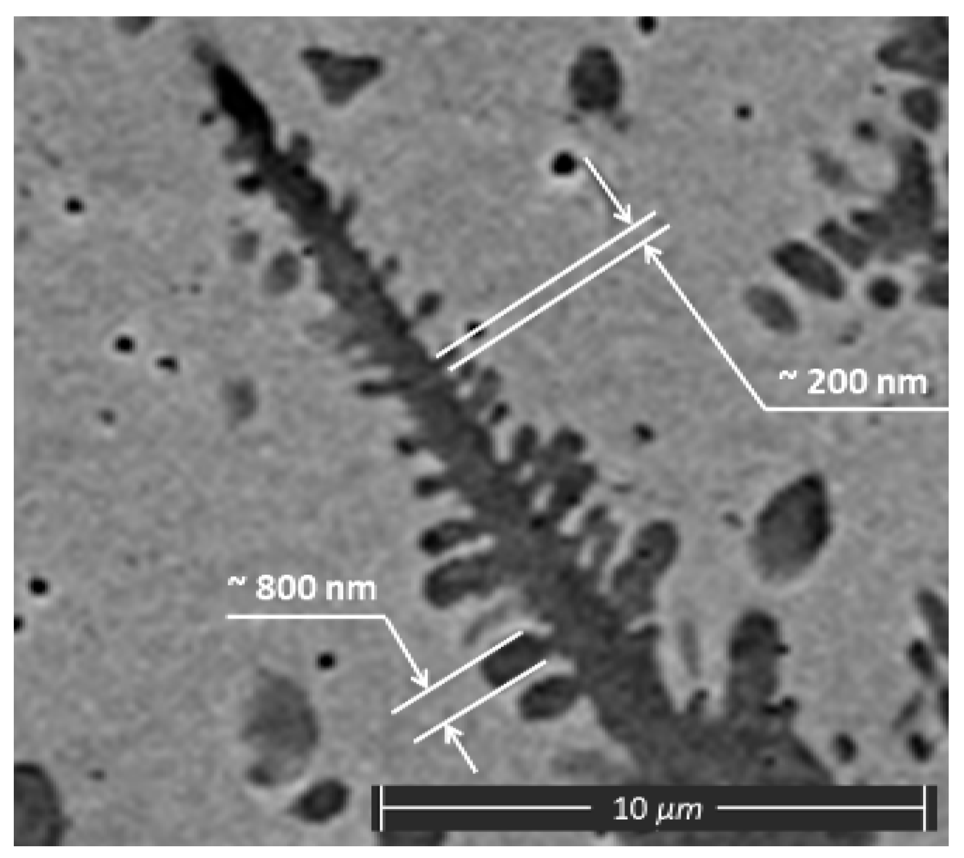
| s, µm | 800 |
| c, µm | 300 |
Publisher’s Note: MDPI stays neutral with regard to jurisdictional claims in published maps and institutional affiliations. |
© 2020 by the authors. Licensee MDPI, Basel, Switzerland. This article is an open access article distributed under the terms and conditions of the Creative Commons Attribution (CC BY) license (http://creativecommons.org/licenses/by/4.0/).
Share and Cite
Makarenko, K.; Dubinin, O.; Shishkovsky, I. Analytical Evaluation of the Dendritic Structure Parameters and Crystallization Rate of Laser-Deposited Cu-Fe Functionally Graded Materials. Materials 2020, 13, 5665. https://doi.org/10.3390/ma13245665
Makarenko K, Dubinin O, Shishkovsky I. Analytical Evaluation of the Dendritic Structure Parameters and Crystallization Rate of Laser-Deposited Cu-Fe Functionally Graded Materials. Materials. 2020; 13(24):5665. https://doi.org/10.3390/ma13245665
Chicago/Turabian StyleMakarenko, Konstantin, Oleg Dubinin, and Igor Shishkovsky. 2020. "Analytical Evaluation of the Dendritic Structure Parameters and Crystallization Rate of Laser-Deposited Cu-Fe Functionally Graded Materials" Materials 13, no. 24: 5665. https://doi.org/10.3390/ma13245665