
A Review on Microcellular Injection Moulding


Abstract
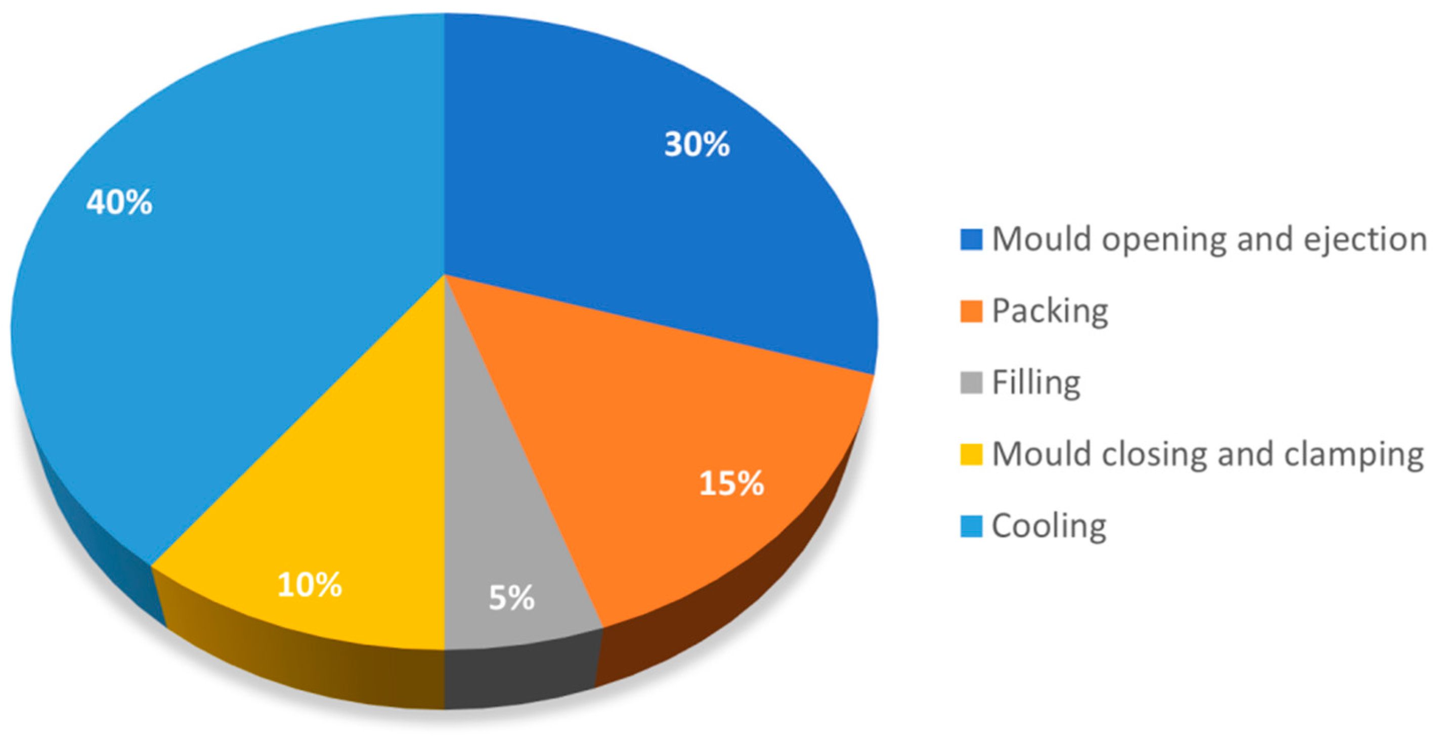
:1. Introduction
- Plastic injection;
- Holding and packing;
- Cooling and solidification;
- Mould opening and part ejection.
2. The MuCell® Process
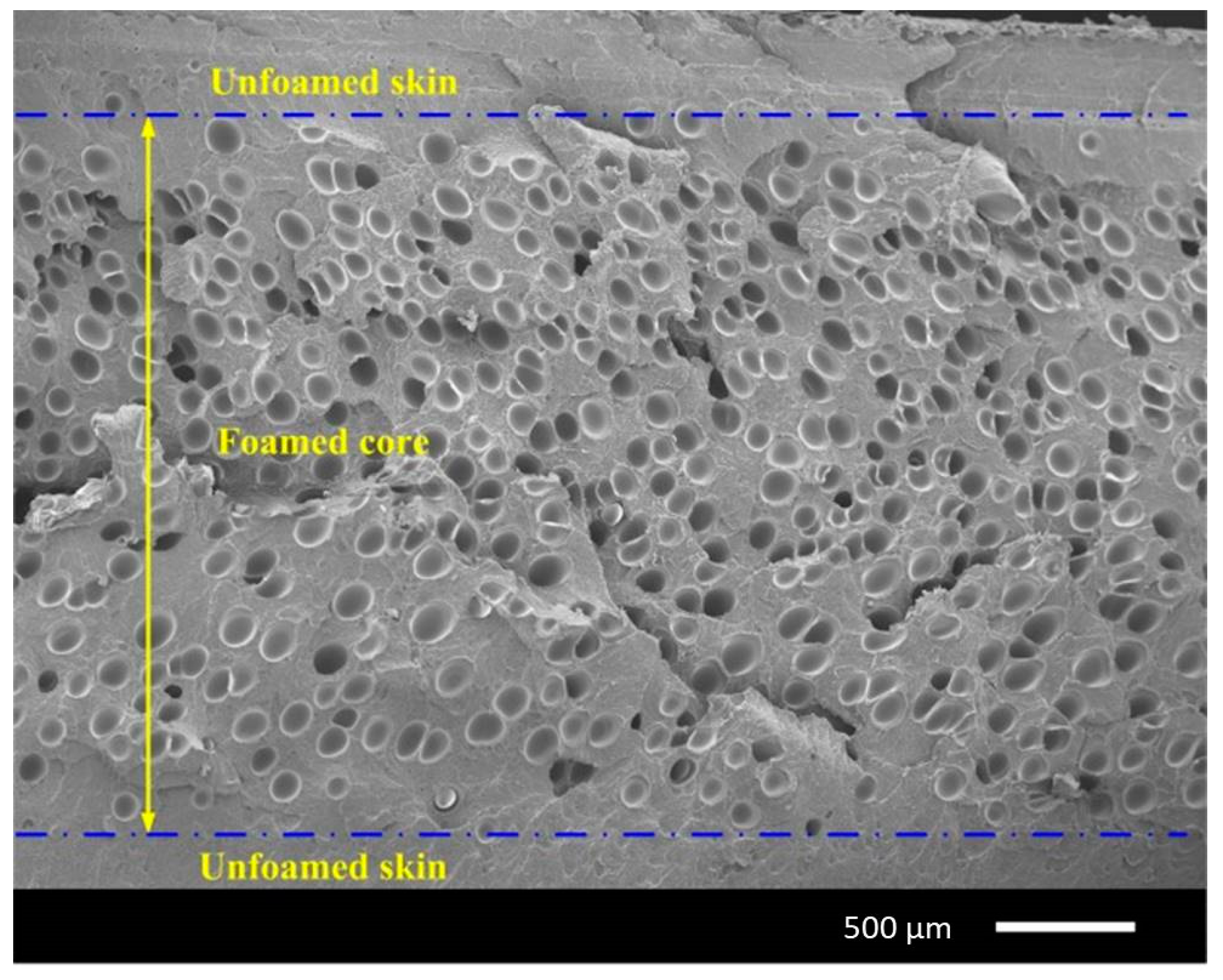
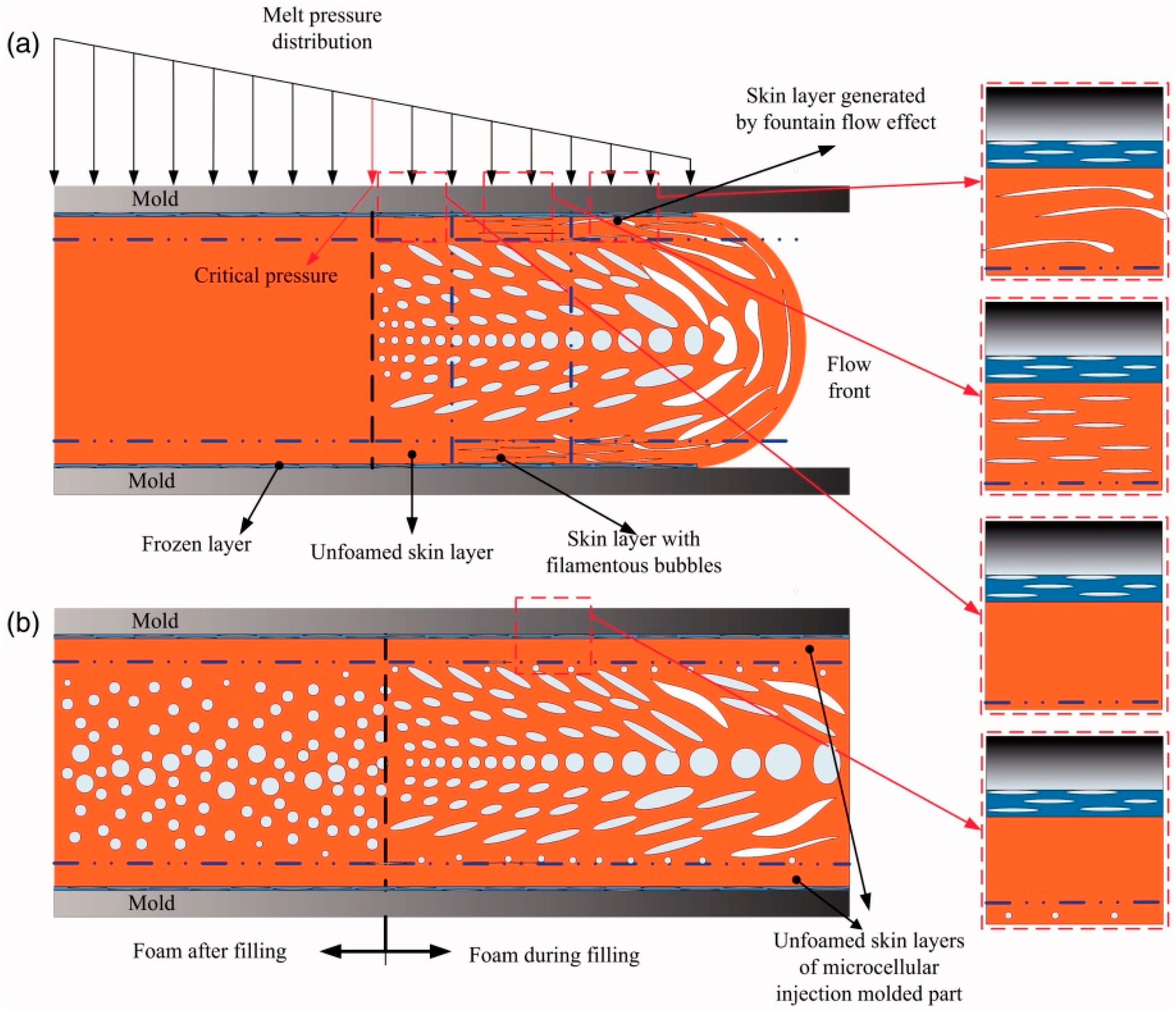
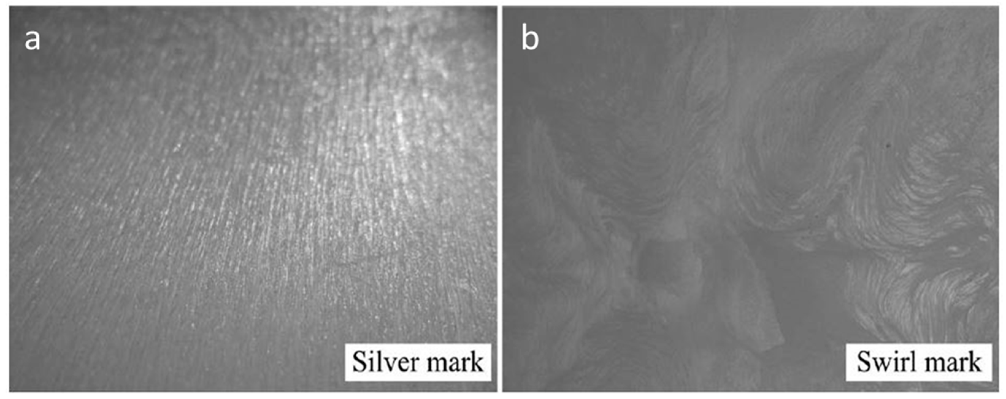
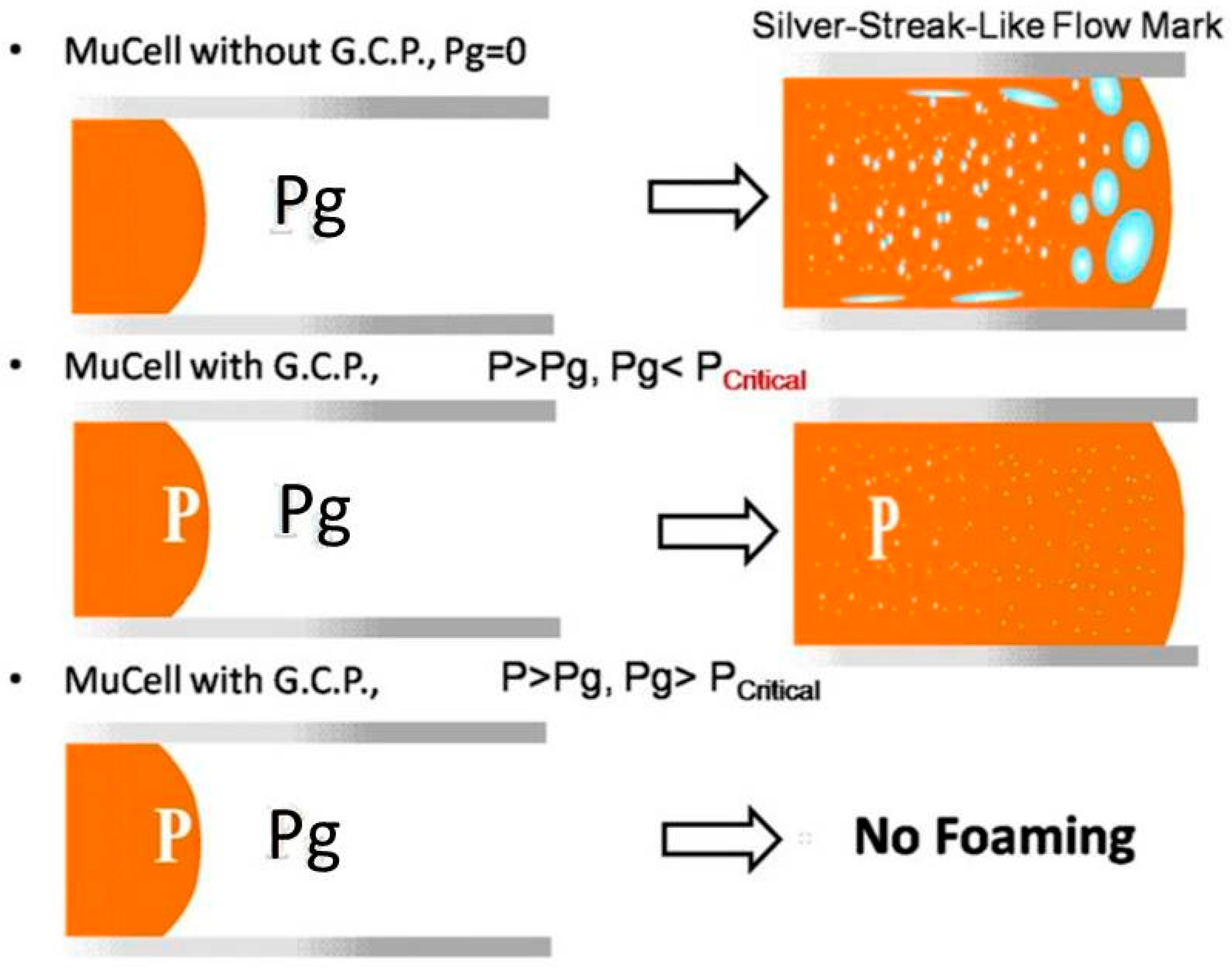
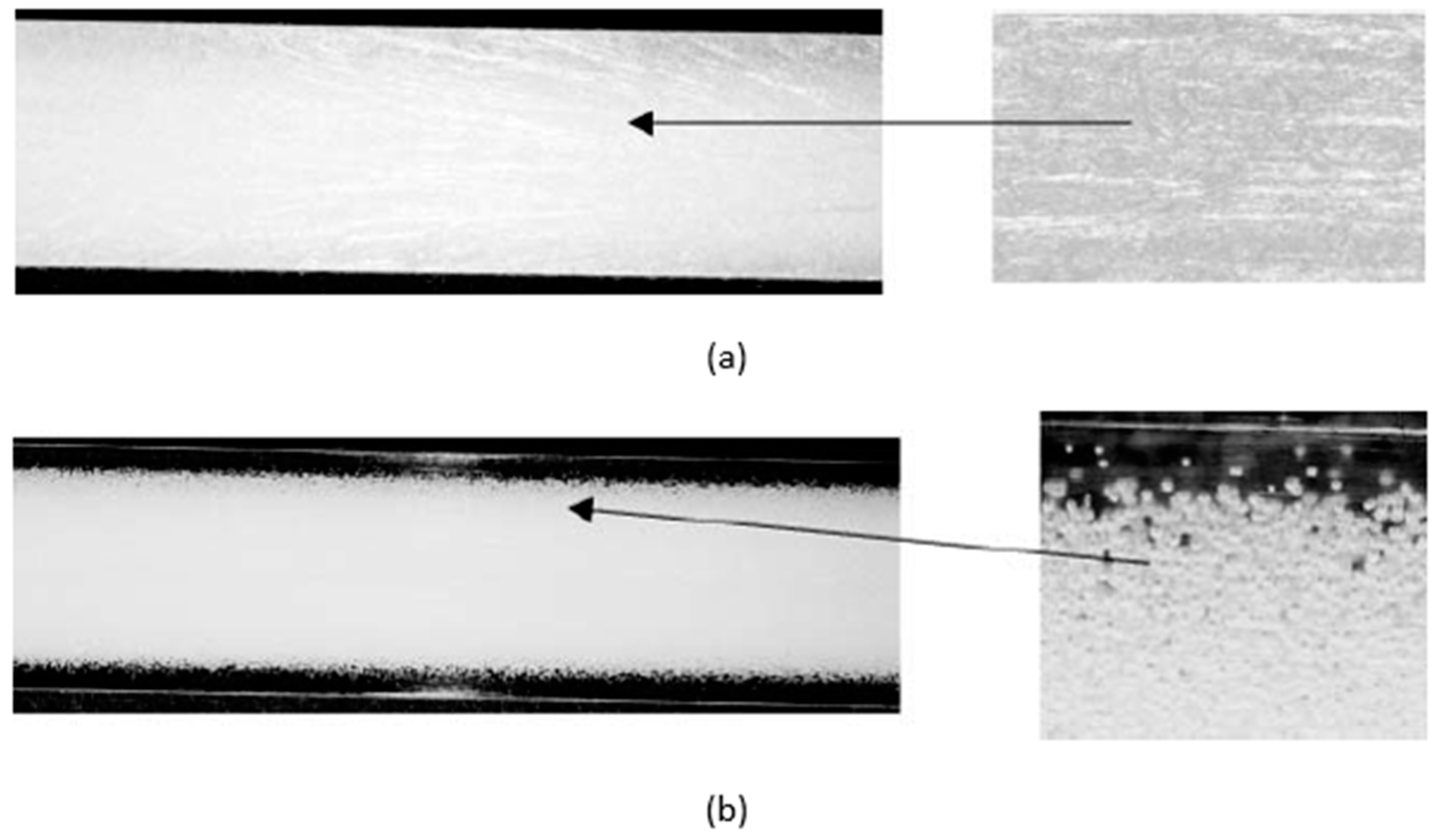
3. Silver Marks and Solid Skin Formation
4. Methods for Improving Mechanical Properties
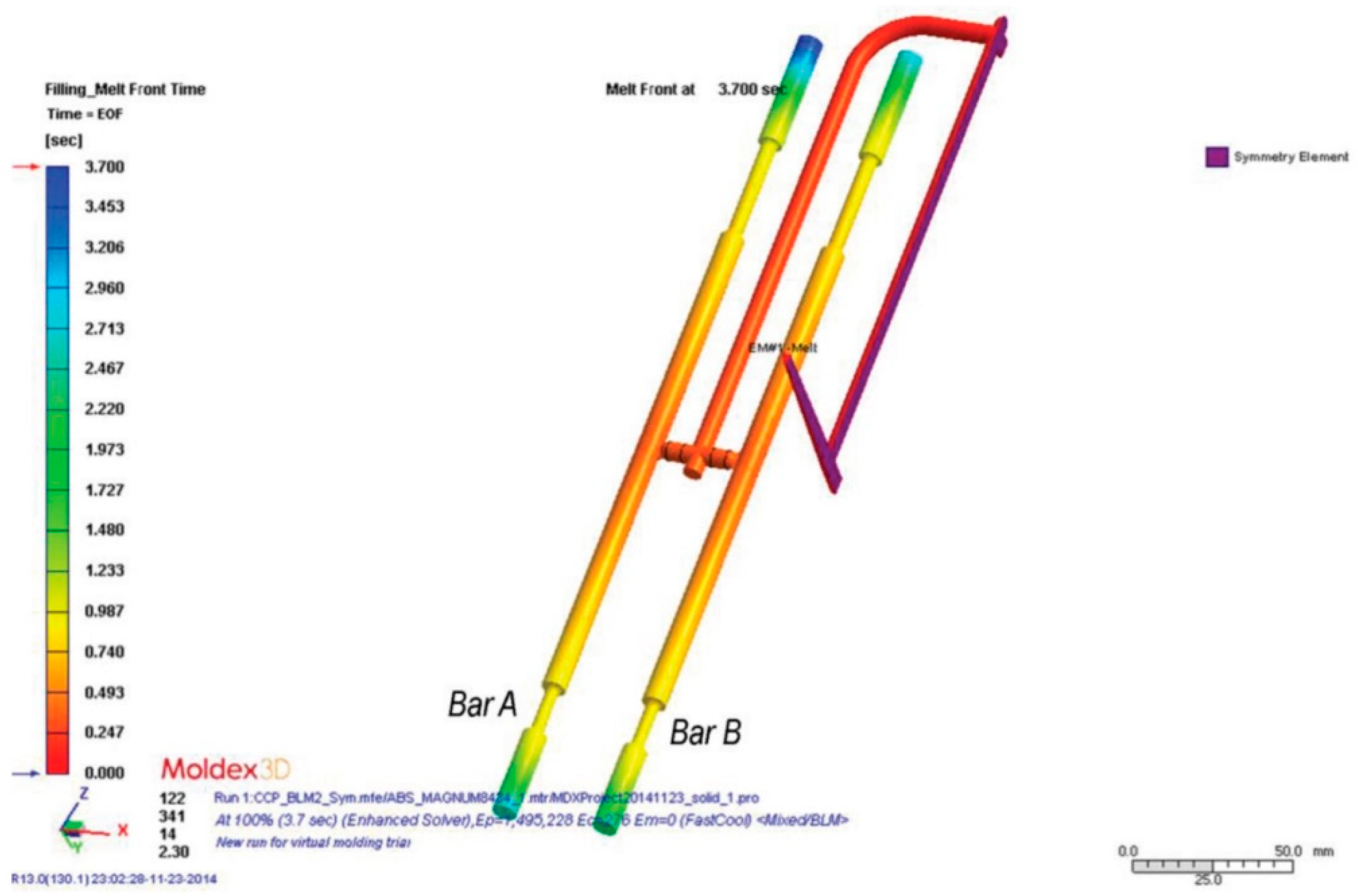
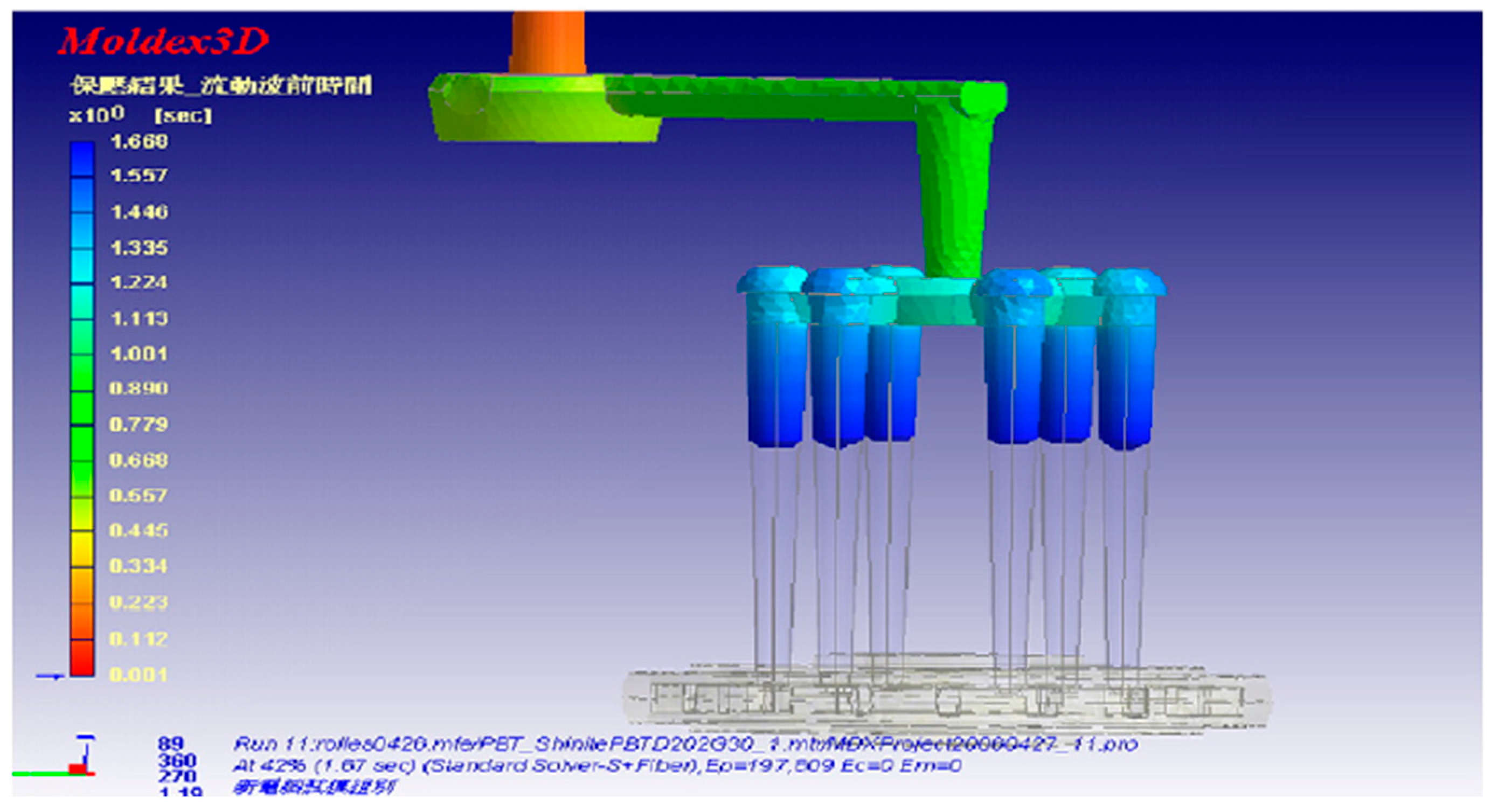
5. Simulation of the MuCell® Process
6. Conclusions and Prospects
Author Contributions
Funding
Institutional Review Board Statement
Informed Consent Statement
Data Availability Statement
Conflicts of Interest
References
- Geyer, R.; Jambeck, J.; Law, K. Production, use, and fate of all plastics ever made. Sci. Adv. 2017, 3, e1700782. [Google Scholar] [CrossRef] [Green Version]
- Plastics Europe. Plastics—The Facts 2018. An Analysis of European Latest Plastics Production, Demand and Waste Data; Plastics Europe: Brussels, Belgium, 2018. [Google Scholar]
- Distribution of Global Plastic Materials Production in 2019, by Region. Available online: https://www.statista.com/statistics/281126/global-plastics-production-share-of-various-countries-and-regions/ (accessed on 8 April 2021).
- European Bioplastics. Bioplastics—Facts and Figures; European Bioplastics: Berlin, Germany, 2019. [Google Scholar]
- Wang, G.; Zhao, G.; Dong, G.; Mu, Y.; Park, C.B. Lightweight and strong microcellular injection molded PP/talc nanocomposite. Compos. Sci. Technol. 2018, 168, 38–46. [Google Scholar] [CrossRef]
- Faruk, O.; Bledzki, A.K.; Matuana, L.M. Microcellular foamed wood-plastic composites by different processes: A review. Macromol. Mater. Eng. 2007, 292, 113–127. [Google Scholar] [CrossRef]
- Ramos-De Valle, L.F. Principles of polymer processing. In Handbook of Polymer Synthesis, Characterization, and Processing, 1st ed.; Saldívar-Guerra, E., Vivaldo-Lima, E., Eds.; John Wiley & Sons: Hoboken, NJ, USA, 2013; pp. 451–461. [Google Scholar]
- Tadmor, Z.; Gogos, C.G. Principles of Polymer Processing, 2nd ed.; John Wiley & Sons: Hoboken, NJ, USA, 2013; pp. 1–984. [Google Scholar]
- Pearson, J.R. Mechanics of Polymer Processing; Springer Science & Business Media: Dordrecht, The Netherlands, 1985; pp. 1–712. [Google Scholar]
- Fernandes, C.; Pontes, A.J.; Viana, J.C.; Gaspar-Cunha, A. Modeling and optimization of the injection-molding process: A Review. Adv. Polym. Technol. 2018, 37, 429–449. [Google Scholar] [CrossRef]
- Khosravani, M.R.; Nasiri, S. Injection molding manufacturing process: Review of case-based reasoning applications. J. Intell. Manuf. 2020, 31, 847–864. [Google Scholar] [CrossRef]
- Rosato, D.V.; Rosato, M.G. Injection Molding Handbook, 3rd ed.; Springer Science & Business Media: New York, NY, USA, 2012; pp. 1–1460. [Google Scholar]
- Goodship, V. 4—Injection molding of thermoplastics. In Design and Manufacture of Plastic Components for Multifunctionality; Goodship, V., Middleton, B., Cherrington, R., Eds.; William Andrew Publishing: Oxford, UK, 2016; pp. 103–170. [Google Scholar]
- Okolieocha, C.; Raps, D.; Subramaniam, K.; Altstädt, V. Microcellular to nanocellular polymer foams: Progress (2004–2015) and future directions—A review. Eur. Polym. J. 2015, 73, 500–519. [Google Scholar] [CrossRef]
- Banerjee, R.; Ray, S.S. Foamability and special applications of microcellular thermoplastic polymers: A review on recent advances and future direction. Macromol. Mater. Eng. 2020, 305, 2000366. [Google Scholar] [CrossRef]
- Xu, J. Microcellular Injection Molding; John Wiley & Sons: Hoboken, NJ, USA, 2011; pp. 1–632. [Google Scholar]
- Štěpek, J.; Daoust, H. Chemical and physical blowing agents. In Additives for Plastics; Springer: New York, NY, USA, 1983; Volume 5, pp. 112–123. [Google Scholar]
- Iannace, S.; Park, C.B. Biofoams: Science and Applications of Bio-Based Cellular and Porous Materials; CRC Press: Boca Raton, FL, USA, 2015; pp. 1–466. [Google Scholar]
- Han, C.D.; Kim, Y.W.; Malhotra, K.D. A study of foam extrusion using a chemical blowing agent. J. Appl. Polym. Sci. 1976, 20, 1583–1595. [Google Scholar] [CrossRef]
- Kutz, M. Applied Plastics Engineering Handbook: Processing and Materials; Elsevier Science: Amsterdam, The Netherlands, 2011; pp. 1–574. [Google Scholar]
- Wang, G.; Zhao, G.Q.; Wang, J.; ZHANG, L. Research on formation mechanisms and control of external and inner bubble morphology in microcellular injection molding. Polym. Eng. Sci. 2015, 55, 807–835. [Google Scholar] [CrossRef]
- Błędzki, A.K.; Faruk, O.; Kirschling, H.; Kuehn, J.; Jaszkiewicz, A. Microcellular polymers and composites. Polimery 2006, 51, 697–703. [Google Scholar]
- Gómez-Monterde, J.; Hain, J.; Sanchez-Soto, M.; Maspoch, M.L. Microcellular injection moulding: A comparison between MuCell process and the novel micro-foaming technology IQ Foam. J. Mater. Process. Technol. 2019, 268, 162–170. [Google Scholar] [CrossRef]
- Elduque, D.; Clavería, I.; Fernández, Á.; Javierre, C.; Pina, C.; Santolaria, J. Analysis of the influence of microcellular injection molding on the environmental impact of an industrial component. Adv. Mech. Eng. 2014, 6, 793269. [Google Scholar] [CrossRef]
- Martini, J. The Production and Analysis of Microcellular Foam. Master’s Thesis, Massachusetts Institute of Technology, Cambridge, MA, USA, January 1981. [Google Scholar]
- Doroudiani, S.; Park, C.B.; Kortschot, M.T. Processing and characterization of microcellular foamed high-density polythylene/isotactic polypropylene blends. Polym. Eng. Sci. 1998, 38, 1205–1215. [Google Scholar] [CrossRef]
- Colton, J.S.; Suh, N.P. Nucleation of microcellular foam: Theory and practice. Polym. Eng. Sci. 1987, 27, 500–503. [Google Scholar] [CrossRef]
- Chong, T.H.; Ha, Y.W.; Jeong, D.J. Effect of dissolved gas on the viscosity of HIPS in the manufacture of microcellular plastics. Polym. Eng. Sci. 2003, 43, 1337–1344. [Google Scholar] [CrossRef]
- Siripurapu, S.; Gay, Y.J.; Royer, J.R.; DeSimone, J.M.; Spontak, R.J.; Khan, S.A. Generation of microcellular foams of PVDF and its blends using supercritical carbon dioxide in a continuous process. Polymer 2002, 43, 5511–5520. [Google Scholar] [CrossRef]
- Xu, J.; Pierick, D. Microcellular foam processing in reciprocating-screw injection molding machines. J. Inject. Molding Technol. 2001, 5, 152. [Google Scholar]
- Kharbas, H.; Nelson, P.; Yuan, M.; Gong, S.; Turng, L.S.; Spindler, R. Effects of nano-fillers and process conditions on the microstructure and mechanical properties of microcellular injection molded polyamide nanocomposites. Polym. Compos. 2003, 24, 655–671. [Google Scholar] [CrossRef]
- Gong, S.; Yuan, M.; Chandra, A.; Kharbas, H.; Osorio, A.; Turng, L. Microcellular injection molding. Int. Polym. Process. 2005, 20, 202–214. [Google Scholar] [CrossRef]
- Cardona, J. Short Screw Designs for the MuCell Process. Master’s Thesis, University of Massachusetts Lowell, Lowell, MA, USA, June 2004. [Google Scholar]
- Gómez-Monterde, J.; Sánchez-Soto, M.; Maspoch, M.L. Influence of injection molding parameters on the morphology, mechanical and surface properties of ABS foams. Adv. Polym. Technol. 2018, 37, 2707–2720. [Google Scholar] [CrossRef]
- Oprea-Kiss, A.; Kiss, I. About the numerous cost and processing advantages of the microcellular foam injection molding process for thermoplastics materials in the automobile industry. Anal. Tech. Szeged. 2015, 9, 6–14. [Google Scholar] [CrossRef]
- Pierick, D.; Janisch, R. Microcellular foam molding technology. In Proceedings of the Blowing Agents 99, Blowing Agent Systems: Formulation and Processing Conference, Manchester, UK, 9–10 December 1999. [Google Scholar]
- Goel, S.K.; Beckman, E.J. Generation of microcellular polymeric foams using supercritical carbon dioxide. I: Effect of pressure and temperature on nucleation. Polym. Eng. Sci. 1994, 34, 1137–1147. [Google Scholar] [CrossRef]
- Shaayegan, V.; Wang, C.; Costa, F.; Han, S.; Park, C.B. Effect of the melt compressibility and the pressure drop rate on the cell-nucleation behavior in foam injection molding with mold opening. Eur. Polym. J. 2017, 92, 314–325. [Google Scholar] [CrossRef]
- Wu, H.; Wintermantel, E.; Haugen, H.J. The effects of mold design on the pore morphology of polymers produced with MuCell® Technology. J. Cell. Plast. 2010, 46, 519–530. [Google Scholar] [CrossRef]
- Suh, N.P. Impact of microcellular plastics on industrial practice and academic research. In Proceedings of the IUPAC Polymer Conference on Mission and Challenges of Polymer Science and Technology, Kyoto, Japan, 2–5 December 2002. [Google Scholar]
- Colton, J.S. The nucleation of microcellular foams in semi crystalline thermoplastics. Mater. Manuf. Process. 1989, 4, 253–262. [Google Scholar] [CrossRef]
- Colton, J.S. The Nucleation of Microcellular Thermoplastic Foam. Ph.D. Thesis, Massachusetts Institute of Technology, Cambridge, MA, USA, September 1985. [Google Scholar]
- Colton, J.; Suh, N. The nucleation of microcellular thermoplastic foam with additives: Part I: Theoretical considerations. Polym. Eng. Sci. 1987, 27, 485–492. [Google Scholar] [CrossRef]
- Colton, J.; Suh, N. The nucleation of microcellular thermoplastic foam with additives: Part II: Experimental results and discussion. Polym. Eng. Sci. 1987, 27, 493–499. [Google Scholar] [CrossRef]
- Colton, J.; Suh, N. The nucleation of microcellular thermoplastic foam: Process model and experimental results. Mater. Manuf. Process. 1986, 1, 341–364. [Google Scholar] [CrossRef]
- Moon, Y.; Cha, S.W.; Seo, J.-h. Bubble nucleation and growth in microcellular injection molding processes. Polym. Plast. Technol. Eng. 2008, 47, 420–426. [Google Scholar] [CrossRef]
- Dong, G.; Zhao, G.; Guan, Y.; Wang, G.; Wang, X. The cell forming process of microcellular injection-molded parts. J. Appl. Polym. Sci. 2014, 131, 40365. [Google Scholar] [CrossRef]
- Waldman, F.A. The Processing of Microcellular Foam. Master’s Thesis, Massachusetts Institute of Technology, Cambridge, MA, USA, January 1982. [Google Scholar]
- Behravesh, A.; Rajabpour, M. Experimental study on filling stage of microcellular injection molding process. Cell. Polym. 2006, 25, 85–97. [Google Scholar] [CrossRef]
- Ishikawa, T.; Ohshima, M. Visual observation and numerical studies of polymer foaming behavior of polypropylene/carbon dioxide system in a core-back injection molding process. Polym. Eng. Sci. 2011, 51, 1617–1625. [Google Scholar] [CrossRef]
- Wang, L.; Ando, M.; Kubota, M.; Ishihara, S.; Hikima, Y.; Ohshima, M.; Sekiguchi, T.; Sato, A.; Yano, H. Effects of hydrophobic-modified cellulose nanofibers (CNFs) on cell morphology and mechanical properties of high void fraction polypropylene nanocomposite foams. Compos. Part A Appl. Sci. Manuf. 2017, 98, 166–173. [Google Scholar] [CrossRef]
- Lee, J.J.; Cha, S.W. Characteristics of the skin layers of microcellular injection molded parts. Polym. Plast. Technol. Eng. 2007, 45, 871–877. [Google Scholar] [CrossRef]
- Kuo, Y.; Kamal, M.R. The fluid mechanics and heat transfer of injection mold filling of thermoplastic materials. AIChE J. 1976, 22, 661–669. [Google Scholar] [CrossRef]
- Ohta, T.; Yokoi, H. Visual analysis of cavity filling and packing process in injection molding of thermoset phenolic resin by the gate-magnetization method. Polym. Eng. Sci. 2001, 41, 806–819. [Google Scholar] [CrossRef]
- Frutiger, R. The effect of flow on cavity surface temperatures in thermoset and thermoplastic injection molding. Polym. Eng. Sci. 1986, 26, 243–254. [Google Scholar] [CrossRef]
- Dong, G.; Zhao, G.; Guan, Y.; Li, S.; Wang, X. Formation mechanism and structural characteristics of unfoamed skin layer in microcellular injection-molded parts. J. Cell. Plast. 2015, 52, 419–439. [Google Scholar] [CrossRef]
- Cha, S.W.; Yoon, J.D. The relationship of mold temperatures and swirl marks on the surface of microcellular plastics. Polym. Plast. Technol. Eng. 2005, 44, 795–803. [Google Scholar] [CrossRef]
- Zhang, L.; Zhao, G.; Wang, G.; Dong, G.; Wu, H. Investigation on bubble morphological evolution and plastic part surface quality of microcellular injection molding process based on a multiphase-solid coupled heat transfer model. Int. J. Heat Mass Transf. 2017, 104, 1246–1258. [Google Scholar] [CrossRef]
- Chen, S.C.; Hsu, P.S.; Hwang, S.S. The effects of gas counter pressure and mold temperature variation on the surface quality and morphology of the microcellular polystyrene foams. J. Appl. Polym. Sci. 2013, 127, 4769–4776. [Google Scholar] [CrossRef]
- Wang, Y.; Hu, G.H. Research progress of improving surface quality of microcellular foam injection parts. In Proceedings of the International Conference on Mechanical Materials and Manufacturing Engineering, Nanchang, China, 20–22 June 2011. [Google Scholar]
- Bledzki, A.K.; Kirschling, H.; Steinbichler, G.; Egger, P. Polycarbonate microfoams with a smooth surface and higher notched impact strength. J. Cell. Plast. 2004, 40, 489–496. [Google Scholar] [CrossRef]
- Chen, S.C.; Liao, W.H.; Chien, R.D. Structure and mechanical properties of polystyrene foams made through microcellular injection molding via control mechanisms of gas counter pressure and mold temperature. Int. Commun. Heat Mass Transf. 2012, 39, 1125–1131. [Google Scholar] [CrossRef]
- Hou, J.; Zhao, G.Q.; Wang, G.; Dong, G.; Xu, J. A novel gas-assisted microcellular injection molding method for preparing lightweight foams with superior surface appearance and enhanced mechanical performance. Mater. Des. 2017, 127, 115–125. [Google Scholar] [CrossRef]
- Wang, G.; Zhao, G.; Guan, Y. Thermal response of an electric heating rapid heat cycle molding mold and its effect on surface appearance and tensile strength of the molded part. J. Appl. Polym. Sci. 2013, 128, 1339–1352. [Google Scholar] [CrossRef]
- Dong, G.W.; Zhao, G.Q.; Zhang, L.; Hou, J.; Li, B.; Wang, G. Morphology evolution and elimination mechanism of bubble marks on surface of microcellular injection-molded parts with dynamic mold temperature control. Ind. Eng. Chem. Res. 2018, 57, 1089–1101. [Google Scholar] [CrossRef]
- Chen, S.; Lin, Y.; Chien, R.D.; Li, H.M. Variable mold temperature to improve surface quality of microcellular injection molded parts using induction heating technology. Adv. Polym. Technol. 2008, 27, 224–232. [Google Scholar] [CrossRef]
- Chen, S.; Chang, C.; Tseng, C.; Shen, E.; Feng, C. Using P (pressure)-T (temperature) path to control the foaming cell sizes in microcellular injection molding process. Polymers 2021, 13, 1843. [Google Scholar] [CrossRef]
- Yoon, J.D.; Hong, S.K.; Kim, J.H.; Cha, S.W. A mold surface treatment for improving surface finish of injection molded microcellular parts. Cell. Polym. 2004, 23, 39–48. [Google Scholar] [CrossRef]
- Chen, H.L.; Chien, R.D.; Chen, S.C. Using thermally insulated polymer film for mold temperature control to improve surface quality of microcellular injection molded parts. Int. Commun. Heat Mass Transf. 2008, 35, 991–994. [Google Scholar] [CrossRef]
- Lee, J.; Turng, L.S.; Dougherty, E.; Gorton, P. A novel method for improving the surface quality of microcellular injection molded parts. Polymer 2011, 52, 1436–1446. [Google Scholar] [CrossRef]
- Bledzki, A.K.; Kirschling, H.; Rohleder, M.; Chate, A. Correlation between injection moulding processing parameters and mechanical properties of microcellular polycarbonate. J. Cell. Plast. 2012, 48, 301–340. [Google Scholar] [CrossRef]
- Lee, J.J.; Cha, S.W. Influence of mould temperature on the thickness of a skin layer and impact strength in the microcellular injection moulding process. Cell. Polym. 2005, 24, 279. [Google Scholar] [CrossRef]
- Kastner, C.; Steinbichler, G.; Kahlen, S.; Jerabek, M. Influence of process parameters on mechanical properties of physically foamed, fiber reinforced polypropylene parts. J. Appl. Polym. Sci. 2018, 136, 47275. [Google Scholar] [CrossRef]
- Gómez-Monterde, J.; Sánchez-Soto, M.; Maspoch, M.L. Microcellular PP/GF composites: Morphological, mechanical and fracture characterization. Compos. Part A Appl. Sci. Manuf. 2018, 104, 1–13. [Google Scholar] [CrossRef]
- Sun, X.; Kharbas, H.; Peng, J.; Turng, L.S. Fabrication of super ductile polymeric blends using microcellular injection molding. Manuf. Lett. 2014, 2, 64–68. [Google Scholar] [CrossRef]
- Lee, J.; Turng, L.S.; Kramschuster, A. The microcellular injection molding of low-density polyethylene (LDPE) composites. Polym. Plast. Technol. Eng. 2010, 49, 1339–1346. [Google Scholar] [CrossRef]
- Yan, K.; Guo, W.; Mao, H.; Yang, Q.; Meng, Z. Investigation on foamed PP/Nano-CaCO3 composites in a combined in-mold decoration and microcellular injection molding process. Polymers 2020, 12, 363. [Google Scholar] [CrossRef] [Green Version]
- Llewelyn, G.; Rees, A.; Griffiths, C.A.; Jacobi, M. A novel hybrid foaming method for low-pressure microcellular foam production of unfilled and talc-filled copolymer polypropylenes. Polymers 2019, 11, 1896. [Google Scholar] [CrossRef] [PubMed] [Green Version]
- Ding, J.; Ma, W.; Song, F.; Zhong, Q. Effect of nano-calcium carbonate on microcellular foaming of polypropylene. J. Mater. Sci. 2013, 48, 2504–2511. [Google Scholar] [CrossRef]
- Gómez-Monterde, J.; Schulte, M.; Ilijevic, S.; Hain, J.; Arencón, D.; Sánchez-Soto, M.; Maspoch, M.L. Morphology and mechanical characterization of ABS foamed by microcellular injection molding. Procedia Eng. 2015, 132, 15–22. [Google Scholar] [CrossRef] [Green Version]
- Tao, Y.; Hinduja, S.; Heinemann, R.; Gomes, A.; Bártolo, P.J. A study of physico-mechanical properties of hollow glass bubble, jute fibre and rubber powder reinforced polypropylene compounds with and without MuCell® technology for lightweight applications. Polymers 2020, 12, 2664. [Google Scholar] [CrossRef] [PubMed]
- Heim, H.P.; Tromm, M. General aspects of foam injection molding using local precision mold opening technology. Polymer 2015, 56, 111–118. [Google Scholar] [CrossRef]
- Chang, R.; Yang, W. Numerical simulation of mold filling in injection molding using a three-dimensional finite volume approach. Int. J. Numer. Methods Fluids 2001, 37, 125–148. [Google Scholar] [CrossRef]
- Shiu, T. Dynamic behavior and experimental validation of cell nucleation and growing mechanism in microcellular injection molding process. In Proceedings of the ANTEC, Orlando, FL, USA, 2–4 April 2012; Society of Petroleum Engineers: Dallas, TX, USA, 2012. [Google Scholar]
- Taki, K. Experimental and numerical studies on the effects of pressure release rate on number density of bubbles and bubble growth in a polymeric foaming process. Chem. Eng. Sci. 2008, 63, 3643–3653. [Google Scholar] [CrossRef]
- Streeter, V.; Kestin, J. Handbook of Fluid Dynamics; McGraw-Hill Inc.: New York, NY, USA, 1961; pp. 1–1228. [Google Scholar]
- Han, C.; Yoo, H.J. Studies on structural foam processing. IV. Bubble growth during mold filling. Polym. Eng. Sci. 1981, 21, 518–533. [Google Scholar] [CrossRef]
- Moldex3D Help. 2020. Available online: http://support.moldex3d.com/2020/en/7-6-4-4_mathematicalmodelsandassumptions.html (accessed on 15 March 2021).
- Fitted Classical Nucleation Model. Available online: https://knowledge.autodesk.com/support/moldflow-insight/learn-explore/caas/CloudHelp/cloudhelp/2018/ENU/MoldflowInsight/files/GUID-8B03BE7A-DD9A-422C-AE50-BA215A3B8EF8-htm.html (accessed on 29 March 2021).
- Viscosity Model for Microcellular Injection Molding. Available online: https://knowledge.autodesk.com/support/moldflow-insight/learn-explore/caas/CloudHelp/cloudhelp/2018/ENU/MoldflowInsight/files/GUID-64C6F313-6CD4-4CAB-A950-F907BF85F3D9-htm.html (accessed on 17 April 2021).
- Hwang, S.S.; Hsu, P.P.; Chiang, C.W. Shrinkage study of textile roller molded by conventional/microcellular injection-molding process. Int. Commun. Heat Mass Transf. 2008, 35, 735–743. [Google Scholar] [CrossRef]
- Xi, Z.; Chen, J.; Liu, T.; Zhao, L.; Turng, L.S. Experiment and simulation of foaming injection molding of polypropylene/nano-calcium carbonate composites by supercritical carbon dioxide. Chin. J. Chem. Eng. 2016, 24, 180–189. [Google Scholar] [CrossRef]
- Bujanić, B.; Šercer, M.; Rujnić-Sokele, M. Comparison of Moldex3d and Moldflow injection moulding simulations. In Proceedings of the 10th International Research/Expert Conference, Barcelona, Spain, 11–15 September 2006. [Google Scholar]
- Kramschuster, A.; Cavitt, R.; Ermer, D.; Chen, Z.; Turng, L.S. Quantitative study of shrinkage and warpage behavior for microcellular and conventional injection molding. Polym. Eng. Sci. 2005, 45, 1408–1418. [Google Scholar] [CrossRef]
- Febra, M.; Vasco, J.; Capela, C. Mechanical characterization of thermoplastic polymers foamed by microcellular injection moulding. In Proceedings of the PMI 2018—Polymers and Moulds Innovations, Guimaraes, Portugal, 19–21 September 2018. [Google Scholar]
- Li, J.; Chen, Z.; Wang, X.; Liu, T.; Zhou, Y.; Luo, S. Cell morphology and mechanical properties of microcellular mucell® injection molded polyetherimide and polyetherimide/fillers composite foams. J. Appl. Polym. Sci. 2013, 130, 4171–4181. [Google Scholar] [CrossRef]
- Lohr, C.; Beck, B.; Henning, F.; Weidenmann, K.A.; Elsner, P. Process comparison on the microstructure and mechanical properties of fiber-reinforced polyphenylene sulfide using MuCell technology. J. Reinf. Plast. Compos. 2018, 37, 1020–1034. [Google Scholar] [CrossRef]
- Liu, T.; Liu, H.; Li, L.; Wang, X.; Lu, A.; Luo, S. Microstructure and properties of microcellular poly (phenylene sulfide) foams by Mucell injection molding. Polym. Plast. Technol. Eng. 2013, 52, 440–445. [Google Scholar] [CrossRef]
- Mi, H.Y.; Jing, X.; Peng, J.; Turng, L.S.; Peng, X.F. Influence and prediction of processing parameters on the properties of microcellular injection molded thermoplastic polyurethane based on an orthogonal array test. J. Cell. Plast. 2013, 49, 439–458. [Google Scholar] [CrossRef]
- Yoon, J.; Kuboki, T.; Jung, P.; Wang, J.; Park, C. Injection molding of wood-fiber/plastic composite foams. Compos. Interfaces 2009, 16, 797–811. [Google Scholar] [CrossRef]
- Chen, S.C.; Yang, J.P.; Hwang, J.S.; Chung, M.H. Effects of process conditions on the mechanical properties of microcellular injection molded polycarbonate parts. J. Reinf. Plast. Compos. 2008, 27, 153–165. [Google Scholar] [CrossRef]
- Hwang, S.; Chen, S.; Chung, M. Study on the mechanical properties of microcellular injection molded parts. In Proceedings of the ANTEC, Boston, MA, USA, 1–5 May 2005. [Google Scholar]
- Volpe, V.; Lanzillo, S.; Affinita, G.; Villacci, B.; Macchiarolo, I.; Pantani, R. Lightweight high-performance polymer composite for automotive applications. Polymers 2019, 11, 326. [Google Scholar] [CrossRef] [Green Version]
- Yuan, M.; Turng, L.S.; Gong, S.; Caulfield, D.; Hunt, C.; Spindler, R. Study of injection molded microcellular polyamide-6 nanocomposites. Polym. Eng. Sci. 2004, 44, 673–686. [Google Scholar] [CrossRef]
- Kim, H.K.; Sohn, J.S.; Ryu, Y.; Kim, S.W.; Cha, S.W. Warpage reduction of glass fiber reinforced plastic using microcellular foaming process applied injection molding. Polymers 2019, 11, 360. [Google Scholar] [CrossRef] [PubMed] [Green Version]
- Sykutera, D.; Czyżewski, P.; Szewczykowski, P. The microcellular structure of injection molded thick-walled parts as observed by in-line monitoring. Materials 2020, 13, 5464. [Google Scholar] [CrossRef] [PubMed]
- Tabatabaei, A.; Mark, L.H.; Park, C.B. Visualization of polypropylene crystallites formed from a stressed melt in extrusion. Polymer 2016, 101, 48–58. [Google Scholar] [CrossRef]
- Zhao, P.; Zhao, Y.; Kharbas, H.; Zhang, J.; Wu, T.; Yang, W.; Fu, J.; Turng, L.S. In-situ ultrasonic characterization of microcellular injection molding. J. Mater. Process. Technol. 2019, 270, 254–264. [Google Scholar] [CrossRef]
- Zhao, Y.; Zhao, P.; Zhang, J.; Huang, J.; Xia, N.; Fu, J. On-line measurement of clamping force for injection molding machine using ultrasonic technology. Ultrasonics 2019, 91, 170–179. [Google Scholar] [CrossRef]
- Yusa, A.; Yamamoto, S.; Goto, H.; Uezono, H.; Asaoka, F.; Wang, L.; Ando, M.; Ishihara, S.; Ohshima, M. A new microcellular foam injection-molding technology using non-supercritical fluid physical blowing agents. Polym. Eng. Sci. 2017, 57, 105–113. [Google Scholar] [CrossRef]
- Pontes, A.J.; Queirós, M.P.; Martinho, P.G.; Bártolo, P.J.; Pouzada, A.S. Experimental assessment of hybrid mould performance. Int. J. Adv. Manuf. Technol. 2010, 50, 441–448. [Google Scholar] [CrossRef]
- Martinho, P.G.; Bártolo, P.J.; Pouzada, A.S. Hybrid moulds: Effect of the moulding blocks on the morphology and dimensional properties. Rapid Prototyp. J. 2009, 15, 71–82. [Google Scholar] [CrossRef]


| Material | Parameters | Changes | Morphology | Skin Thickness | Apparent Density | Weight Reduction | Warpage | Mechanical Properties | Reference | |||||||||
|---|---|---|---|---|---|---|---|---|---|---|---|---|---|---|---|---|---|---|
| Tensile | Impact | Flexural | Biaxial Bending | |||||||||||||||
| Cell Size | Cell Number (Density) | Elastic Modulus | Yield Strength | Tensile Strength | Young’s Modulus | Flexural Strength | Bending Stiffness | Maximum Force | Energy | |||||||||
| ABS | shot volume | ↓ | ↓ | ↑ | ↓ | ↓ | ↑ | ↓ | ↓ | [34] | ||||||||
| SCF content | ↑ | ↓ | ↑ | ↓ | ↓ | ↓ | ||||||||||||
| mould temperature | ↑ | ↓ | ↑ | ↑ | no | no | no | |||||||||||
| injection velocity | ↑ | ↓ | ↑ | ↓ | no | no | no | |||||||||||
| PP/GF | mould temperature | ↑ | ↓ | no | no | no | no | ↓ | ↓ | [73,74] | ||||||||
| degree of foaming | ↓ | ↑ | ↑ | ↓ | ↓ | ↓ | ||||||||||||
| injection speed | not clear | |||||||||||||||||
| delay time | ↓ | ↓ | ↓ | ↓ | ↓ | ↑ | ↑ | |||||||||||
| gas content | ↓ | ↑ | no | |||||||||||||||
| MuCell process pressure (MPP) | ||||||||||||||||||
| shot volume | ↓ | ↓ | ↓ | ↓ | ↓ | ↓ | ||||||||||||
| PP, PP/CaCo3, ABS | SCF content | ↑ | ↓ | ↓ | ↓ | [95] | ||||||||||||
| PEI | shot size | ↑ | ↓ | ↑ | ↑ | ↓ | ↑ | ↑ | ↑ | [96] | ||||||||
| SCF content | ↑ | ↑ | ↓ | ↓ | ↑ | ↓ | ↓ | ↓ | ||||||||||
| injection speed | ↑ | ↓ | ↑ | ↑ | ↓ | ↑ | ↑ | ↑ | ||||||||||
| mould temperature | ↑ | ↓ | ||||||||||||||||
| PPS/GF | injection speed | ↑ | no | no | ↓ | no | no | [97] | ||||||||||
| PPS | shot size | ↑ | ↓ | ↑ | ↑ | ↑ | ↑ | ↑ | ↑ | [98] | ||||||||
| SCF content | ↑ | ↓ | ↑ | no | no | no | ||||||||||||
| TPU | plasticising temperature | ↑ | ↑ | ↑ until 200 °C then ↓ | ↑ until 198 °C then ↓ | [99] | ||||||||||||
| injection speed | ↑ | ↓ | ↑ until 45 ccm/s then ↓ | ↑ until 40 ccm/s then ↓ | ||||||||||||||
| injection volume | ↓ | |||||||||||||||||
| SCF content | ↓ | ↑ | ↓ | no | ||||||||||||||
| HDPE/Wood fibre | gas content | ↑ | ↑ | [100] | ||||||||||||||
| injection speed | ↑ | ↑ | ||||||||||||||||
| mould temperature | ↑ | |||||||||||||||||
| weight reduction | ↓ | ↑ | ↑ | ↑ | ||||||||||||||
| PC | melt temperature | ↑ | ↑ | ↑ | [101,102] | |||||||||||||
| mould temperature | ↑ | ↑ | ↓ | |||||||||||||||
| MPP | ↑ | no | ↓ | |||||||||||||||
| SCF content | ↑ | ↑ | not clear | |||||||||||||||
| injection rate | ↑ | ↑ | not clear | |||||||||||||||
| shot size | ↑ | ↑ | not clear | |||||||||||||||
| PA66/GF | injection temperature | ↑ | ↓ | ↑ | [103] | |||||||||||||
| gas injection pressure | ↑ | ↓ | ↑ | ↑ | ||||||||||||||
| PA6 | shot size | ↑ | ↓ | ↓ | ↑ | [104] | ||||||||||||
| melt temperature | ||||||||||||||||||
| SCF content | ||||||||||||||||||
| injection speed | ||||||||||||||||||
| PA6/Clay | shot size | ↑ | ↑ until 18.4 mm then ↓ | ↑ until 18.4 mm then ↓ | ↑ | [104] | ||||||||||||
| melt temperature | ↑ | no | no | |||||||||||||||
| SCF content | ↑ | no | no | |||||||||||||||
| injection speed | ↑ | no | no | |||||||||||||||
| PP/GF | SCF content | ↑ | ↓ | ↓ | [105] | |||||||||||||
| PP/talc | SCF content | ↑ | ↓ | [94] | ||||||||||||||
| PS | mould temperature | ↑ | ↑ | no | ↓ | ↓ | ↓ | [59,62] | ||||||||||
Publisher’s Note: MDPI stays neutral with regard to jurisdictional claims in published maps and institutional affiliations. |
© 2021 by the authors. Licensee MDPI, Basel, Switzerland. This article is an open access article distributed under the terms and conditions of the Creative Commons Attribution (CC BY) license (https://creativecommons.org/licenses/by/4.0/).
Share and Cite
Ding, Y.; Hassan, M.H.; Bakker, O.; Hinduja, S.; Bártolo, P. A Review on Microcellular Injection Moulding. Materials 2021, 14, 4209. https://doi.org/10.3390/ma14154209
Ding Y, Hassan MH, Bakker O, Hinduja S, Bártolo P. A Review on Microcellular Injection Moulding. Materials. 2021; 14(15):4209. https://doi.org/10.3390/ma14154209
Chicago/Turabian StyleDing, Yifei, Mohammed H. Hassan, Otto Bakker, Srichand Hinduja, and Paulo Bártolo. 2021. "A Review on Microcellular Injection Moulding" Materials 14, no. 15: 4209. https://doi.org/10.3390/ma14154209
APA StyleDing, Y., Hassan, M. H., Bakker, O., Hinduja, S., & Bártolo, P. (2021). A Review on Microcellular Injection Moulding. Materials, 14(15), 4209. https://doi.org/10.3390/ma14154209