
Cast Iron Parts Obtained in Ceramic Molds Produced by Binder Jetting 3D Printing—Morphological and Mechanical Characterization

 ,
,  ,
,  ,
,  ,
,  ,
, 
 and
and
Abstract
:1. Introduction
2. Materials and Methods
3. Results
3.1. Tensile Test of Cast Iron Samples Made by Gravitational Casting in Ceramic Molds Made of 3D Printing
3.2. Finite Element Analysis Performed in the Abaqus Program of the “Hydraulic Block” Part, Taking into Consideration the Results Obtained Concerning the Tensile Test of the Cast Iron Test Samples
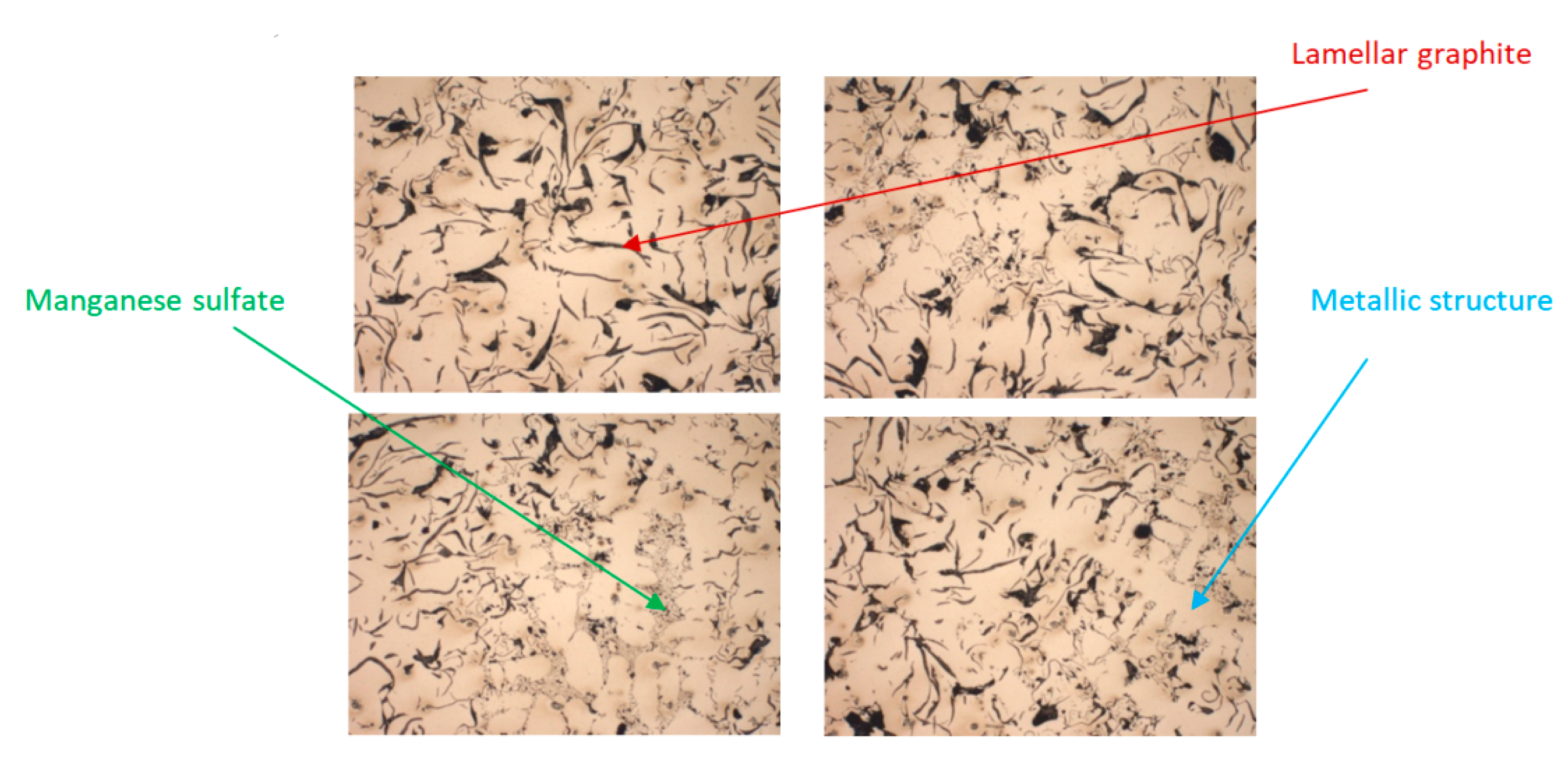
3.3. Microstructural and Chemical Analysis of Samples of Cast Iron with Lamellar Graphite Type EN-GJL-250 and Cast Iron with Spheroidal Graphite Type EN-GJS-400-15
4. Conclusions
- The results reached after finite element analyses emphasized that when a pressure of 25 MPa is being applied, in the case of the parts made of cast iron with lamellar graphite of type EN-GJL-250 a safety factor of at least 1.5 (normal value used in hydraulic applications) is not guaranteed, this condition being ensured only for cast iron of type EN-GJS-400-15.
- The results of the tensile tests revealed that cast iron with spheroidal graphite type EN-GJS-400-15 has higher tensile strength as compared to the ones made of EN-GJL-250 material, specific deformations that were reached being also much lower in this variant. The samples made of cast iron with spheroidal graphite type EN-GJS-400-15 had an elongation of about 20% before breaking, as compared to those made of cast iron with lamellar graphite type EN-GJL-250 which suffered a sudden fracture.
- SEM analyses performed for the fracture areas of the samples revealed that the EN-GJL-250 sheet metal cast iron is a 100% pearlite cast iron, which makes the resulting parts hard but very fragile, and the spheroidal cast iron of type EN-GJS-400-15 has in its structure approximately 80% ferrite and 20% pearlite, with ferrite giving it higher plasticity. The presence of magnesium concentration in case of EN-GJS-400-15 material is an element that determines the nodular shape of the graphite in the structure, improving its mechanical behavior and characteristics of realized parts at the end.
Author Contributions
Funding
Institutional Review Board Statement
Informed Consent Statement
Data Availability Statement
Conflicts of Interest
References
- Ma, Z.J.; Tao, D.; Yang, Z.; Guo, Y.C.; Li, J.P.; Liang, M.X.; Yeung, L.T.L. The effect of vermicularity on the thermal con-ductivity of vermicular graphite cast iron. Mater. Des. 2016, 93, 418–422. [Google Scholar] [CrossRef]
- Cooper, C.; Elliott, R.; Young, R. Investigation of elastic property relationships for flake and spheroidal cast irons using Raman spectroscopy. Acta Mater. 2002, 50, 4037–4046. [Google Scholar] [CrossRef]
- Bagnoli, F.; Dolce, F.; Bernabei, M.J.E.F.A. Thermal fatigue cracks of fire fighting vehicles gray iron brake discs. Eng. Fail. Anal. 2009, 16, 152–163. [Google Scholar] [CrossRef]
- Seo, H.; Joo, B.; Park, J.; Kim, Y.C.; Lee, J.J.; Jang, H. Effect of disc material on particulate matter emissions during high-temperature braking. Tribol. Int. 2021, 154, 106713. [Google Scholar] [CrossRef]
- Abreu, M.; Sundberg, J.; Elfsberg, J.; Jonsson, S. Morphology and mechanisms of cavitation damage on lamellar gray iron surfaces. Wear 2020, 456–457, 203324. [Google Scholar] [CrossRef]
- Grigoriev, S.; Metel, A.; Tarasova, T.; Filatova, A.; Sundukov, S.; Volosova, M.; Okunkova, A.; Melnik, Y.; Podrabinnik, P. Effect of Cavitation Erosion Wear, Vibration Tumbling, and Heat Treatment on Additively Manufactured Surface Quality and Properties. Metals 2020, 10, 1540. [Google Scholar] [CrossRef]
- Lin, J.; Wang, Z.; Cheng, J.; Kang, M.; Fu, X.; Hong, S. Effect of Initial Surface Roughness on Cavitation Erosion Resistance of Arc-Sprayed Fe-Based Amorphous/Nanocrystalline Coatings. Coatings 2017, 7, 200. [Google Scholar] [CrossRef] [Green Version]
- Sarkar, T.; Sutradhar, G. Influence of austenitizing temperature on microstructure and mechanical properties of austempered gray iron (AGI). Mater. Today Proc. 2017, 4, 10138–10143. [Google Scholar] [CrossRef]
- Luu, H.-T.; Veiga, R.G.A.; Gunkelmann, N. Atomistic Study of the Role of Defects on α → ϵ Phase Transformations in Iron under Hydrostatic Compression. Metals 2019, 9, 1040. [Google Scholar] [CrossRef] [Green Version]
- Hutiu, G.; Duma, V.-F.; Demian, D.; Bradu, A.; Podoleanu, A.G. Assessment of Ductile, Brittle, and Fatigue Fractures of Met-als Using Optical Coherence Tomography. Metals 2018, 8, 117. [Google Scholar] [CrossRef] [Green Version]
- Lehmhus, D.; Weise, J.; Szlancsik, A.; Orbulov, I.N. Fracture Toughness of Hollow Glass Microsphere-Filled Iron Matrix Syntactic Foams. Materials 2020, 13, 2566. [Google Scholar] [CrossRef]
- Xiang, S.; Jonsson, S.; Badu, R.P.; Zhu, B.; Odqvist, J. Influence of tension and compression dwell on the creep-fatigue properties of the austenitic cast iron Ni-resist D5S. Mater. Sci. Eng. A 2021, 814, 141179. [Google Scholar] [CrossRef]
- Naves, M.; Nijenhuis, M.; Hakvoort, W.; Brouwer, D. Flexure-based 60 degrees stroke actuator suspension for a high torque iron core motor. Precis. Eng. 2020, 63, 105–114. [Google Scholar] [CrossRef]
- Machuta, J.; Nová, I. Metallurgy of the Grey Cast Iron for the Automotive Parts, Metallofiz. Noveishie Tekhnol. 2017, 39, 1267–1279. [Google Scholar] [CrossRef]
- Sama, S.R.; Macdonald, E.; Voigt, R.; Manogharan, G. Measurement of Metal Velocity in Sand Casting during Mold Filling. Metals 2019, 9, 1079. [Google Scholar] [CrossRef] [Green Version]
- Venkat, Y.; Choudary, K.R.; Das, D.K.; Pandey, A.K.; Singh, S. Ceramic shell moulds for investment casting of low-pressure turbine rotor blisk. Ceram. Int. 2021, 47, 5663–5670. [Google Scholar] [CrossRef]
- Sadarang, J.; Nayak, R.K.; Panigrahi, I. Effect of binder and moisture content on compactibility and shear strength of river bed green sand mould. Mater. Today Proc. 2020, 46, 5286–5290. [Google Scholar] [CrossRef]
- Sivarupan, T.; Balasubramani, N.; Saxena, P.; Nagarajan, D.; El Mansori, M.; Salonitis, K.; Jolly, M.; Dargusch, M.S. A review on the progress and challenges of binder jet 3D printing of sand moulds for advanced casting. Addit. Manuf. 2021, 40, 101889. [Google Scholar] [CrossRef]
- Song, L.; Guo, E.; Wang, L.; Liu, D. Effects of Silicon on Mechanical Properties and Fracture Toughness of Heavy-Section Ductile Cast Iron. Metals 2015, 5, 150–161. [Google Scholar] [CrossRef] [Green Version]
- Sánchez-Cru, A.; Bedolla-Jacuinde, A.; Guerra, F.V.; Mejía, I. Microstructural modification of a static and dynamically solid-ified high chromium white cast iron alloyed with vanadium. Results Mater. 2020, 7, 100114. [Google Scholar] [CrossRef]
- Essam, M.A.; Shash, A.Y.; Megahed, H.; El-Kashif, E. Effect of section thickness on microstructure and mechanical properties of compacted graphite iron for diesel engine applications. Heliyon 2021, 7, e05930. [Google Scholar] [CrossRef]
- Yang, W.J.; Pang, J.C.; Wang, L.; Wang, S.G.; Liu, Y.Z.; Hui, L.; Li SXZhang, Z.F. Tensile properties and damage mecha-nisms of compacted graphite iron based on microstructural simulation. Mater. Sci. Eng. A 2021, 814, 141244. [Google Scholar] [CrossRef]
- Shi, G.Q.; Yang, Z.; Li, J.P.; Tao, D.; Ma, Z.J. Investigation on the graphite nucleation and growth mechanism of the compacted graphite iron. J. Mater. Res. Technol. 2020, 9, 8186–8196. [Google Scholar] [CrossRef]
- Czarnecka-Komorowska, D.; Grześkowiak, K.; Popielarski, P.; Barczewski, M.; Gawdzińska, K.; Popławski, M. Polyethylene Wax Modified by Organoclay Bentonite Used in the Lost-Wax Casting Process: Processing−Structure−Property Relationships. Materials 2020, 13, 2255. [Google Scholar] [CrossRef]
- Bondan, S.; Muh, S.; Hafid, K.; Rahmat, N. Modification of Ceramic Mold for Investment Casting with Silica Sand as Stucco and Nylon Addition. Adv. Mater. Res. 2015, 1112, 510–514. [Google Scholar]
- Yang, Q.; Wang, F.; Li, D. Effect of Chopped ZrO2 Fiber Content on the Microstructure and Properties of CaO-Based Integral Ceramic Mold. Materials 2020, 13, 5398. [Google Scholar] [CrossRef]
- Turek, P.; Budzik, G.; Sęp, J.; Oleksy, M.; Józwik, J.; Przeszłowski, Ł.; Paszkiewicz, A.; Kochmański, Ł.; Żelechowski, D. An Analysis of the Casting Polymer Mold Wear Manufactured Using PolyJet Method Based on the Measurement of the Surface Topography. Polymers 2020, 12, 3029. [Google Scholar] [CrossRef] [PubMed]
- Kruth, J.; Mercelis, P.; Van Vaerenbergh, J.; Froyen, L.; Rombouts, M. Binding mechanisms in selective laser sintering and selective laser melting. Rapid Prototyp. J. 2005, 11, 26–36. [Google Scholar] [CrossRef] [Green Version]
- Truxova, V.; Safka, J.; Seidl, M.; Kovalenko, I.; Volensky, L.; Ackermann, M. Ceramic 3D printing: Comparison of SLA and DLP technologies. MM Sci. J. 2020, 2020, 3905–3911. [Google Scholar] [CrossRef]
- Egorov, A.S.; Bogdanovskaya, M.V.; Aleksandrova, D.S.; Osipchik, V.S.; Anokhin, A.S.; Ivanov, V.S.; Ivanov, E.V. Creation of polymer-ceramic materials for FDM printing. J. Phys. Conf. Ser. 2021, 1758, 012010. [Google Scholar] [CrossRef]
- Khoo, Z.X.; Teoh, J.E.M.; Liu, Y.; Chua, C.K.; Yang, S.; An, J.; Leong, K.F.; Yeong, W.Y. 3D printing of smart materials: A review on recent progresses in 4D printing. Virtual Phys. Prototyp. 2015, 10, 103–122. [Google Scholar] [CrossRef]
- Lee, J.M.; Suen, S.K.Q.; Ng, W.L.; Ma, W.C.; Yeong, W.Y. Bioprinting of Collagen: Considerations, Potentials, and Applications. Macromol. Biosci. 2021, 21, e2000280. [Google Scholar] [CrossRef]
- Goh, G.L.; Yeong, W.Y.; Agarwala, S. Aerosol jet printed pH sensor based on carbon nanotubes for flexible electronics. In Proceedings of the 2nd International Conference on Progress in Additive Manufacturing (Pro-AM), Singapore, 17–19 May 2018. [Google Scholar]
- Chavez, L.A.; Ibave, P.; Wilburn, B.; Iv, D.A.; Stewart, C.; Wicker, R.; Lin, Y. The Influence of Printing Parameters, Post-Processing, and Testing Conditions on the Properties of Binder Jetting Additive Manufactured Functional Ceramics. Ceramics 2020, 3, 65–77. [Google Scholar] [CrossRef] [Green Version]
- Kim, E.-H.; Choi, H.-H.; Jung, Y.-G. Fabrication of a ceramic core for an impeller blade using a 3D printing technique and inorganic binder. J. Manuf. Process. 2020, 53, 43–47. [Google Scholar] [CrossRef]
- Miao, G.; Du, W.; Moghadasi, M.; Pei, Z.; Ma, C. Ceramic binder jetting additive manufacturing: Effects of granulation on properties of feedstock powder and printed and sintered parts. Addit. Manuf. 2020, 36, 101542. [Google Scholar] [CrossRef]
- Jimenez, E.M.; Ding, D.; Su, L.; Joshi, A.R.; Singh, A.; BReeja-Jayan, B.; Beuth, J. Parametric analysis to quantify process in-put influence on the printed densities of binder jetted alumina ceramics. Addit. Manuf. 2019, 30, 100864. [Google Scholar]
- Enrique, P.D.; Marzbanrad, E.; Mahmoodkhani, Y.; Keshavarzkermani, A.; Al Momani, H.; Toyserkani, E.; Zhou, N.Y. Design of binder jet additive manufactured co-continuous ceramic-reinforced metal matrix composites. J. Mater. Sci. Technol. 2020, 49, 81–90. [Google Scholar] [CrossRef]
- Budding, A.; Vaneker, T.; Winnubst, A. Open Source Powder based Rapid Prototyping Machine for Ceramics. Procedia CIRP 2013, 6, 533–538. [Google Scholar] [CrossRef] [Green Version]
- Benninger Guss AG Company of Uzwil, Switzerland. Available online: https://www.benningerguss.ch/en/home (accessed on 20 May 2021).
- Germann, H.; Starke, P.; Kerscher, E.; Eifler, D. Fatigue behaviour and lifetime calculation of the cast irons EN-GJL-250, EN-GJS-600 and EN-GJV-400. Procedia Eng. 2010, 2, 1087–1094. [Google Scholar] [CrossRef] [Green Version]
- Roula, A.; Kosnikov, G. Manganese distribution and effect on graphite shape in advanced cast irons. Mater. Lett. 2008, 62, 3796–3799. [Google Scholar] [CrossRef]
- Chemical Composition of GJL 250 Cast Iron Material. Available online: http://www.iron-foundry.com/en-gjl-250-cast-iron-gg25.html (accessed on 30 June 2021).
- Chemical Composition of GJS-400-15 Cast Iron Material. Available online: http://www.iron-foundry.com/en-gjs-400-15-ggg40-cast-iron.html (accessed on 30 June 2021).
- Koriyama, S.; Kanno, T.; Iwami, Y.; Kang, I. Investigation of the Difference Between Carbon Equivalent from Carbon Sat-uration Degree and that from Liquidus. Int. J. Met. 2020, 14, 774–781. [Google Scholar]


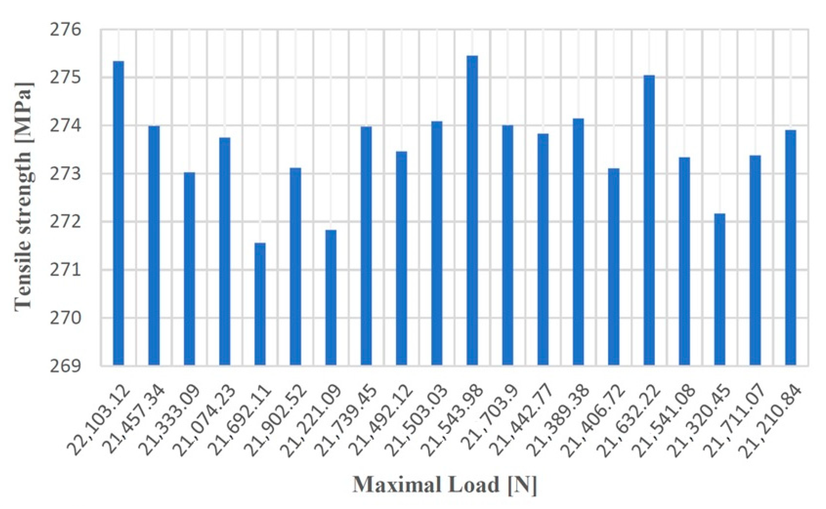
| Test No. | Maximum Loading (N) | Specific Deformation (mm) | Tensile Strength (MPa) | Elongation at Break (%) | Elasticity Modulus (MPa) |
|---|---|---|---|---|---|
| 1 | 22,103.12 | 0.01245 | 275.34 | 1.9 | 37,039.12 |
| 2 | 21,457.34 | 0.01187 | 273.99 | 1.56 | 36,996.34 |
| 3 | 21,333.09 | 0.01156 | 273.03 | 2.04 | 37,010.34 |
| 4 | 21,074.23 | 0.01089 | 273.75 | 0.99 | 37,002.67 |
| 5 | 21,692.11 | 0.01134 | 271.56 | 1.03 | 37,039.11 |
| 6 | 21,902.52 | 0.01239 | 273.12 | 1.79 | 37,056.19 |
| 7 | 21,221.09 | 0.01203 | 271.83 | 2.98 | 36,999.13 |
| 8 | 21,739.45 | 0.01156 | 273.98 | 1.24 | 37,002.19 |
| 9 | 21,492.12 | 0.01194 | 273.46 | 1.2 | 37,001.85 |
| 10 | 21,503.03 | 0.01167 | 274.09 | 1.45 | 36,997.45 |
| 11 | 21,543.98 | 0.01253 | 275.45 | 1.67 | 36,989.73 |
| 12 | 21,703.90 | 0.01212 | 274.01 | 2.05 | 37,000.00 |
| 13 | 21,442.77 | 0.01172 | 273.83 | 1.08 | 37,001.14 |
| 14 | 21,389.38 | 0.01128 | 274.15 | 2.06 | 36,983.18 |
| 15 | 21,406.72 | 0.01201 | 273.11 | 0.95 | 36,999.87 |
| 16 | 21,632.22 | 0.01232 | 275.05 | 2.43 | 37,002.04 |
| 17 | 21,541.08 | 0.01199 | 273.34 | 1.56 | 37,011.01 |
| 18 | 21,320.45 | 0.01185 | 272.17 | 1.77 | 36,896.98 |
| 19 | 21,711.07 | 0.01277 | 273.38 | 2.81 | 37,027.01 |
| 20 | 21,210.84 | 0.01203 | 273.91 | 1.11 | 37,001.06 |
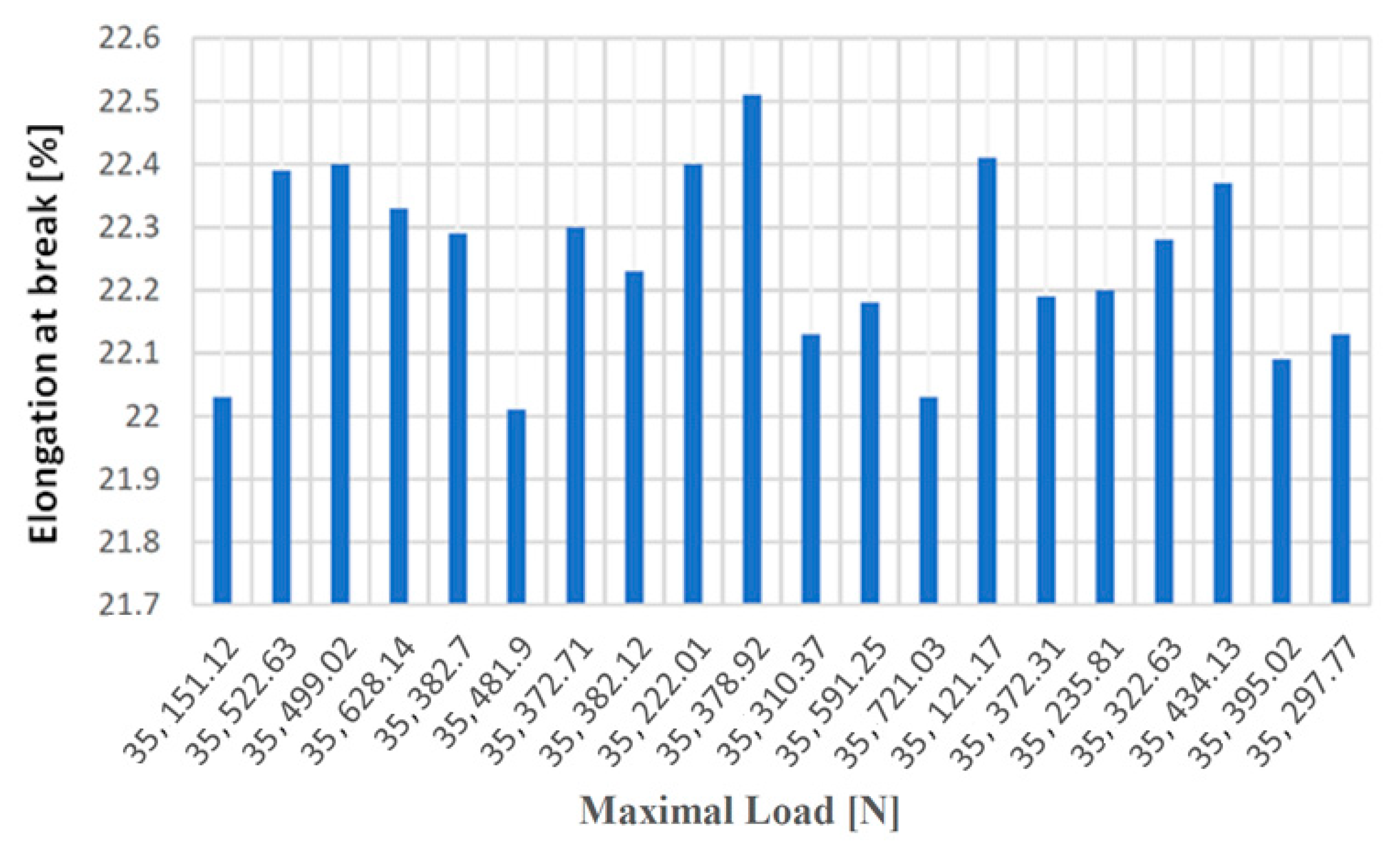
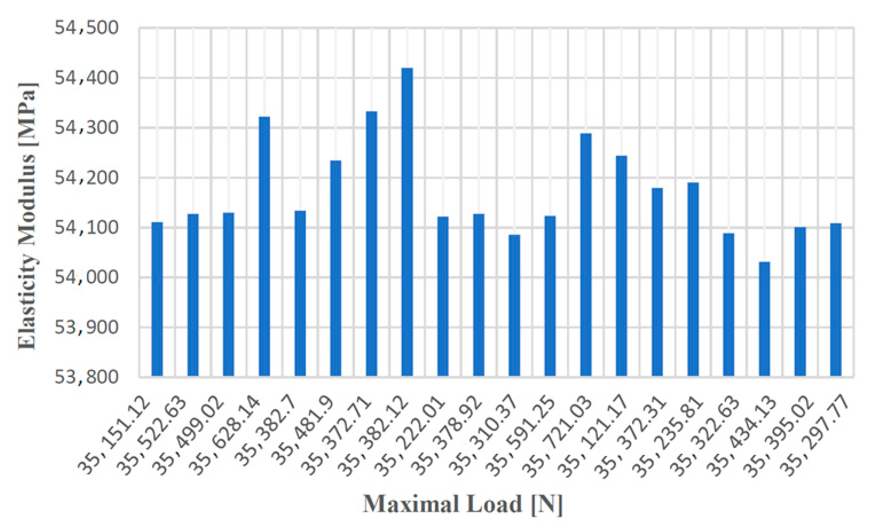
| Test No. | Maximum Loading (N) | Specific Deformation (mm) | Tensile Strength (MPa) | Elongation at Break (%) | Elasticity Modulus (MPa) |
|---|---|---|---|---|---|
| 1 | 35,151.12 | 0.16002 | 417.60 | 22.03 | 54,111.03 |
| 2 | 35,522.63 | 0.16381 | 417.57 | 22.39 | 54,127.35 |
| 3 | 35,499.02 | 0.16306 | 417.57 | 22.40 | 54,129.78 |
| 4 | 35,628.14 | 0.17030 | 417.58 | 22.33 | 54,322.09 |
| 5 | 35,382.70 | 0.16261 | 417.56 | 22.29 | 54,133.67 |
| 6 | 35,481.90 | 0.16333 | 417.58 | 22.01 | 54,234.78 |
| 7 | 35,372.71 | 0.16272 | 417.58 | 22.30 | 54,333.14 |
| 8 | 35,382.12 | 0.16283 | 417.58 | 22.23 | 54,420.03 |
| 9 | 35,222.01 | 0.16234 | 417.59 | 22.40 | 54,122.39 |
| 10 | 35,378.92 | 0.16301 | 417.59 | 22.51 | 54,127.60 |
| 11 | 35,310.37 | 0.16221 | 417.58 | 22.13 | 54,085.69 |
| 12 | 35,591.25 | 0.16451 | 417.59 | 22.18 | 54,123.21 |
| 13 | 35,721.03 | 0.16533 | 417.57 | 22.03 | 54,288.51 |
| 14 | 35,121.17 | 0.16244 | 417.57 | 22.41 | 54,244.06 |
| 15 | 35,372.31 | 0.16202 | 417.58 | 22.19 | 54,179.05 |
| 16 | 35,235,.81 | 0.16281 | 417.58 | 22.20 | 54,190.56 |
| 17 | 35,322.63 | 0.16325 | 417.58 | 22.28 | 54,088.45 |
| 18 | 35,434.13 | 0.16298 | 417.58 | 22.37 | 54,031.56 |
| 19 | 35,395.02 | 0.16182 | 417.58 | 22.09 | 54,100.76 |
| 20 | 35,297.77 | 0.16204 | 417.58 | 22.13 | 54,108.56 |
| Characteristic | Symbol | Measuring Unit | EN-GJL-250 | EN-GJS-400-15 |
|---|---|---|---|---|
| Young Module | 120,000 | 120,000 | ||
| Poisson Ratio | V | - | 0.26 | 0.26 |
| Transversal Elasticity Modulus | 6500 | 6500 | ||
| Density | 7250 | 7250 | ||
| Tensile Strength | 250 | 400 | ||
| Yield strength | 165.59 | 250 | ||
| Coefficient of linear thermal expansion | 1.05 × 10⁻⁵ | 1.05 × 10⁻⁵ | ||
| Thermal Conductivity | 58 | 58 | ||
| Specific heat | 460 | 460 |
| C [%] | Si [%] | Mn [%] | P [%] | S [%] | Cr [%] |
| 3.61 | 2.14 | 0.156 | 0.0127 | 0.0113 | 0.0320 |
| Mo [%] | Ni [%] | Al [%] | Cu [%] | Nb [%] | Ti [%] |
| 0.00759 | 0.216 | 0.0115 | 0.0707 | 0.00133 | 0.00700 |
| V [%] | W [%] | Pb [%] | Sn [%] | Mg [%] | +Bi [%] |
| 0.0105 | 0.00133 | 0.00157 | 0.00442 | 0.0430 | 0.00204 |
| Ca [%] | Ce [%] | Sb [%] | Te [%] | B [%] | Fe [%] |
| 0.0060 | 0.00434 | 0.0004 | 0.00176 | 0.00022 | 93.6 |
| C [%] | Si [%] | Mn [%] | P [%] | S [%] | Cr [%] |
| 3.34 | 1.53 | 0.354 | 0.0377 | 0.0990 | 0.0449 |
| Mo [%] | Ni [%] | Al [%] | Cu [%] | Nb [%] | Ti [%] |
| 0.0115 | 0.0115 | 0.0115 | 0.0115 | 0.0115 | 0.0115 |
| V [%] | W [%] | Pb [%] | Sn [%] | Mg [%] | +Bi [%] |
| 0.00895 | 0.00895 | 0.00895 | 0.00895 | 0.00895 | 0.00895 |
| Ca [%] | Ce [%] | Sb [%] | Te [%] | B [%] | Fe [%] |
| 0.00036 | 0.00112 | 0.0004 | 0.00192 | 0.00011 | 94.2 |
Publisher’s Note: MDPI stays neutral with regard to jurisdictional claims in published maps and institutional affiliations. |
© 2021 by the authors. Licensee MDPI, Basel, Switzerland. This article is an open access article distributed under the terms and conditions of the Creative Commons Attribution (CC BY) license (https://creativecommons.org/licenses/by/4.0/).
Share and Cite
Păcurar, R.; Berce, P.; Nemeş, O.; Băilă, D.-I.; Stan, D.S.; Oarcea, A.; Popişter, F.; Borzan, C.M.; Maricic, S.; Legutko, S.; et al. Cast Iron Parts Obtained in Ceramic Molds Produced by Binder Jetting 3D Printing—Morphological and Mechanical Characterization. Materials 2021, 14, 4502. https://doi.org/10.3390/ma14164502
Păcurar R, Berce P, Nemeş O, Băilă D-I, Stan DS, Oarcea A, Popişter F, Borzan CM, Maricic S, Legutko S, et al. Cast Iron Parts Obtained in Ceramic Molds Produced by Binder Jetting 3D Printing—Morphological and Mechanical Characterization. Materials. 2021; 14(16):4502. https://doi.org/10.3390/ma14164502
Chicago/Turabian StylePăcurar, Răzvan, Petru Berce, Ovidiu Nemeş, Diana-Irinel Băilă, Dan Sergiu Stan, Alexandru Oarcea, Florin Popişter, Cristina Miron Borzan, Sven Maricic, Stanislaw Legutko, and et al. 2021. "Cast Iron Parts Obtained in Ceramic Molds Produced by Binder Jetting 3D Printing—Morphological and Mechanical Characterization" Materials 14, no. 16: 4502. https://doi.org/10.3390/ma14164502