
Effects of a Sodium Phosphate Electrolyte Additive on Elevated Temperature Performance of Spinel Lithium Manganese Oxide Cathodes

Abstract
:
1. Introduction
2. Materials and Methods
2.1. Materials and Electrode Preparation
2.2. Electrochemical Analysis
2.3. Material Characterization
3. Results and Discussion
4. Conclusions
Supplementary Materials
Author Contributions
Funding
Institutional Review Board Statement
Informed Consent Statement
Data Availability Statement
Conflicts of Interest
References
- Dunn, B.; Kamath, H.; Tarascon, J.-M. Electrical energy storage for the grid: A battery of choices. Science 2011, 334, 928–935. [Google Scholar] [CrossRef] [Green Version]
- Chen, S.C.; Wan, C.C.; Wang, Y.Y. Thermal analysis of lithium-ion batteries. J. Power Sources 2005, 140, 111–124. [Google Scholar] [CrossRef]
- Zhu, J.; Wierzbicki, T.; Li, W. A review of safety-focused mechanical modeling of commercial lithium-ion batteries. J. Power Sources 2018, 378, 153–168. [Google Scholar] [CrossRef]
- Xu, B.; Qian, D.; Wang, Z.; Meng, Y.S. Recent progress in cathode materials research for advanced lithium ion batteries. Mater. Sci. Eng. R Rep. 2012, 73, 51–65. [Google Scholar] [CrossRef]
- Fergus, J.W. Recent developments in cathode materials for lithium ion batteries. J. Power Sources 2010, 195, 939–954. [Google Scholar] [CrossRef]
- Li, M.; Lu, J.; Chen, Z.; Amine, K. 30 years of lithium-ion batteries. Adv. Mater. 2018, 30, 1800561. [Google Scholar] [CrossRef] [PubMed] [Green Version]
- Yamane, H.; Inoue, T.; Fujita, M.; Sano, M. A causal study of the capacity fading of Li1.01Mn1.99O4 cathode at 80 °C, and the suppressing substances of its fading. J. Power Sources 2001, 99, 60–65. [Google Scholar] [CrossRef]
- Hirayama, M.; Ido, H.; Kim, K.; Cho, W.; Tamura, K.; Mizuki, J.I.; Kanno, R. Dynamic structural changes at LiMn2O4/electrolyte interface during lithium battery reaction. J. Am. Chem. Soc. 2010, 132, 15268–15276. [Google Scholar] [CrossRef] [PubMed]
- Xia, Y.; Zhou, Y.; Yoshio, M. Capacity fading on cycling of 4 V Li/LiMn2O4 cells. J. Electrochem. Soc. 1997, 144, 2593. [Google Scholar] [CrossRef]
- Amine, K.; Liu, J.; Kang, S.; Belharouak, I.; Hyung, Y.; Vissers, D.; Henriksen, G. Improved lithium manganese oxide spinel/graphite Li-ion cells for high-power applications. J. Power Sources 2004, 129, 14–19. [Google Scholar] [CrossRef]
- Hunter, J.C. Preparation of a new crystal form of manganese dioxide: λ-MnO2. J. Solid State Chem. 1981, 39, 142–147. [Google Scholar] [CrossRef]
- Kim, J.H.; Pieczonka, N.P.W.; Li, Z.C.; Wu, Y.; Harris, S.; Powell, B.R. Understanding the capacity fading mechanism in LiNi0.5Mn1.5O4/graphite Li-ion batteries. Electrochim. Acta 2013, 90, 556–562. [Google Scholar] [CrossRef]
- MahootcheianAsl, N.; Kim, J.H.; Pieczonka, N.P.W.; Liu, Z.Y.; Kim, Y. Multilayer electrolyte cell: A new tool for identifying electrochemical performances of high voltage cathode materials. Electrochem. Commun. 2013, 32, 1–4. [Google Scholar] [CrossRef]
- Ding, Y.L.; Xie, J.; Cao, G.; Zhu, T.; Yu, H.; Zhao, X. Enhanced elevated-temperature performance of Al-doped single-crystalline LiMn2O4 nanotubes as cathodes for lithium ion batteries. J. Phys. Chem. C 2011, 115, 9821–9825. [Google Scholar] [CrossRef]
- Xiong, L.; Xu, Y.; Tao, T.; Goodenough, J.B. Synthesis and electrochemical characterization of multi-cations doped spinel LiMn2O4 used for lithium ion batteries. J. Power Sources 2012, 199, 214–219. [Google Scholar] [CrossRef]
- He, X.; Li, J.; Cai, Y.; Wang, Y.; Ying, J.; Jiang, C.; Wan, C. Fluorine doping of spherical spinel LiMn2O4. Solid State Ion. 2005, 176, 2571–2576. [Google Scholar] [CrossRef]
- Hou, Y.; Chang, K.; Tang, H.; Li, B.; Hou, Y.; Chang, Z. Drastic enhancement in the rate and cyclic behavior of LiMn2O4 electrodes at elevated temperatures by phosphorus doping. Electrochim. Acta 2019, 319, 587–595. [Google Scholar] [CrossRef]
- Arumugam, D.; Kalaignan, G.P. Synthesis and electrochemical characterizations of nano-La2O3-coated nanostructure LiMn2O4 cathode materials for rechargeable lithium batteries. Mater. Res. Bull. 2010, 45, 1825–1831. [Google Scholar] [CrossRef]
- Kim, J.-S.; Johnson, C.; Vaughey, J.; Hackney, S.; Walz, K.; Zeltner, W.; Anderson, M.; Thackeray, M. The Electrochemical Stability of Spinel Electrodes Coated with ZrO2, Al2O3, and SiO2 from Colloidal Suspensions. J. Electrochem. Soc. 2004, 151, A1755–A1761. [Google Scholar] [CrossRef]
- Ha, H.-W.; Yun, N.J.; Kim, K. Improvement of electrochemical stability of LiMn2O4 by CeO2 coating for lithium-ion batteries. Electrochim. Acta 2007, 52, 3236–3241. [Google Scholar] [CrossRef]
- Li, C.; Zhang, H.; Fu, L.; Liu, H.; Wu, Y.; Rahm, E.; Holze, R.; Wu, H. Cathode materials modified by surface coating for lithium ion batteries. Electrochim. Acta 2006, 51, 3872–3883. [Google Scholar] [CrossRef]
- Vidu, R.; Stroeve, P. Improvement of the thermal stability of Li-ion batteries by polymer coating of LiMn2O4. Ind. Eng. Chem. 2004, 43, 3314–3324. [Google Scholar] [CrossRef] [Green Version]
- Ryou, M.-H.; Han, G.-B.; Lee, Y.M.; Lee, J.-N.; Lee, D.J.; Yoon, Y.O.; Park, J.-K. Effect of fluoroethylene carbonate on high temperature capacity retention of LiMn2O4/graphite Li-ion cells. Electrochim. Acta 2010, 55, 2073–2077. [Google Scholar] [CrossRef]
- Li, Y.; Zhang, R.; Liu, J.; Yang, C. Effect of heptamethyldisilazane as an additive on the stability performance of LiMn2O4 cathode for lithium-ion battery. J. Power Sources 2009, 189, 685–688. [Google Scholar] [CrossRef]
- Wang, S.; Hu, H.; Yu, P.; Yang, H.; Cai, X.; Wang, X. Effect of electrolyte additives on high-temperature cycling performance of spinel LiMn2O4 cathode. J. Appl. Electrochem. 2018, 48, 1221–1230. [Google Scholar] [CrossRef]
- Jo, M.; Park, S.-H.; Lee, H. NaH2PO4 as an electrolyte additive for enhanced thermal stability of LiNi0.8Co0.1Mn0.1O2/graphite batteries. J. Electrochem. Soc. 2020, 167, 130502. [Google Scholar] [CrossRef]
- Song, Y.-M.; Kim, C.-K.; Kim, K.-E.; Hong, S.Y.; Choi, N.-S. Exploiting chemically and electrochemically reactive phosphite derivatives for high-voltage spinel LiNi0.5Mn1.5O4 cathodes. J. Power Sources 2016, 302, 22–30. [Google Scholar] [CrossRef]
- Li, B.; Wang, Y.; Rong, H.; Wang, Y.; Liu, J.; Xing, L.; Xu, M.; Li, W. A novel electrolyte with the ability to form a solid electrolyte interface on the anode and cathode of a LiMn2O4/graphite battery. J. Mater. Chem. A 2013, 1, 12954–12961. [Google Scholar] [CrossRef]
- Shi, P.; Zheng, H.; Liang, X.; Sun, Y.; Cheng, S.; Chen, C.; Xiang, H. A highly concentrated phosphate-based electrolyte for high-safety rechargeable lithium batteries. Chem. Commun. 2018, 54, 4453–4456. [Google Scholar] [CrossRef] [PubMed]
- Wu, F.; Tian, J.; Su, Y.; Wang, J.; Zhang, C.; Bao, L.; He, T.; Li, J.; Chen, S. Effect of Ni2+ content on lithium/nickel disorder for Ni-rich cathode materials. ACS Appl. Mater. Interfaces 2015, 7, 7702–7708. [Google Scholar] [CrossRef]
- Pieczonka, N.P.; Liu, Z.; Lu, P.; Olson, K.L.; Moote, J.; Powell, B.R.; Kim, J.-H. Understanding transition-metal dissolution behavior in LiNi0.5Mn1.5O4 high-voltage spinel for lithium ion batteries. J. Phys. Chem. C 2013, 117, 15947–15957. [Google Scholar] [CrossRef]
- Benedek, R.; Thackeray, M. Reaction energy for LiMn2O4 spinel dissolution in acid. Electrochem. Solid-State Lett. 2006, 9, A265–A267. [Google Scholar] [CrossRef]
- Aurbach, D. Review of selected electrode–solution interactions which determine the performance of Li and Li ion batteries. J. Power Sources 2000, 89, 206–218. [Google Scholar] [CrossRef]
- Edström, K.; Herstedt, M.; Abraham, D.P. A new look at the solid electrolyte interphase on graphite anodes in Li-ion batteries. J. Power Sources 2006, 153, 380–384. [Google Scholar] [CrossRef]
- Brutti, S.; Greco, G.; Reale, P.; Panero, S. Insights about the irreversible capacity of LiNi0.5Mn1.5O4 cathode materials in lithium batteries. Electrochim. Acta 2013, 106, 483–493. [Google Scholar] [CrossRef] [Green Version]
- Holtstiege, F.; Wilken, A.; Winter, M.; Placke, T. Running out of lithium? A route to differentiate between capacity losses and active lithium losses in lithium-ion batteries. Phys. Chem. Chem. Phys. 2017, 19, 25905–25918. [Google Scholar] [CrossRef]
- Koo, B.; Lee, J.; Lee, Y.; Kim, J.K.; Choi, N.-S. Vinylene carbonate and tris(trimethylsilyl) phosphite hybrid additives to improve the electrochemical performance of spinel lithium manganese oxide/graphite cells at 60 °C. Electrochim. Acta 2015, 173, 750–756. [Google Scholar] [CrossRef]
- Cho, I.H.; Kim, S.-S.; Shin, S.C.; Choi, N.-S. Effect of SEI on capacity losses of spinel lithium manganese oxide/graphite batteries stored at 60 °C. Electrochem. Solid State Lett. 2010, 13, A168. [Google Scholar] [CrossRef]
- Komaba, S.; Itabashi, T.; Ohtsuka, T.; Groult, H.; Kumagai, N.; Kaplan, B.; Yashiro, H. Impact of 2-vinylpyridine as electrolyte additive on surface and electrochemistry of graphite for C/LiMn2O4 Li-ion cells. J. Electrochem. Soc. 2005, 152, A937. [Google Scholar] [CrossRef]
- Qiu, X.-Y.; Zhuang, Q.-C.; Zhang, Q.-Q.; Cao, R.; Qiang, Y.-H.; Ying, P.-Z.; Sun, S.-G. Investigation of layered LiNi1/3Co1/3Mn1/3O2 cathode of lithium ion battery by electrochemical impedance spectroscopy. J. Electroanal. Chem. 2013, 688, 392. [Google Scholar] [CrossRef]
- Nobili, F.; Dsoke, S.; Croce, F.; Marassi, R. An ac impedance spectroscopic study of Mg-doped LiCoO2 at different temperatures: Electronic and ionic transport properties. Electrochim. Acta 2005, 50, 2307–2313. [Google Scholar] [CrossRef]

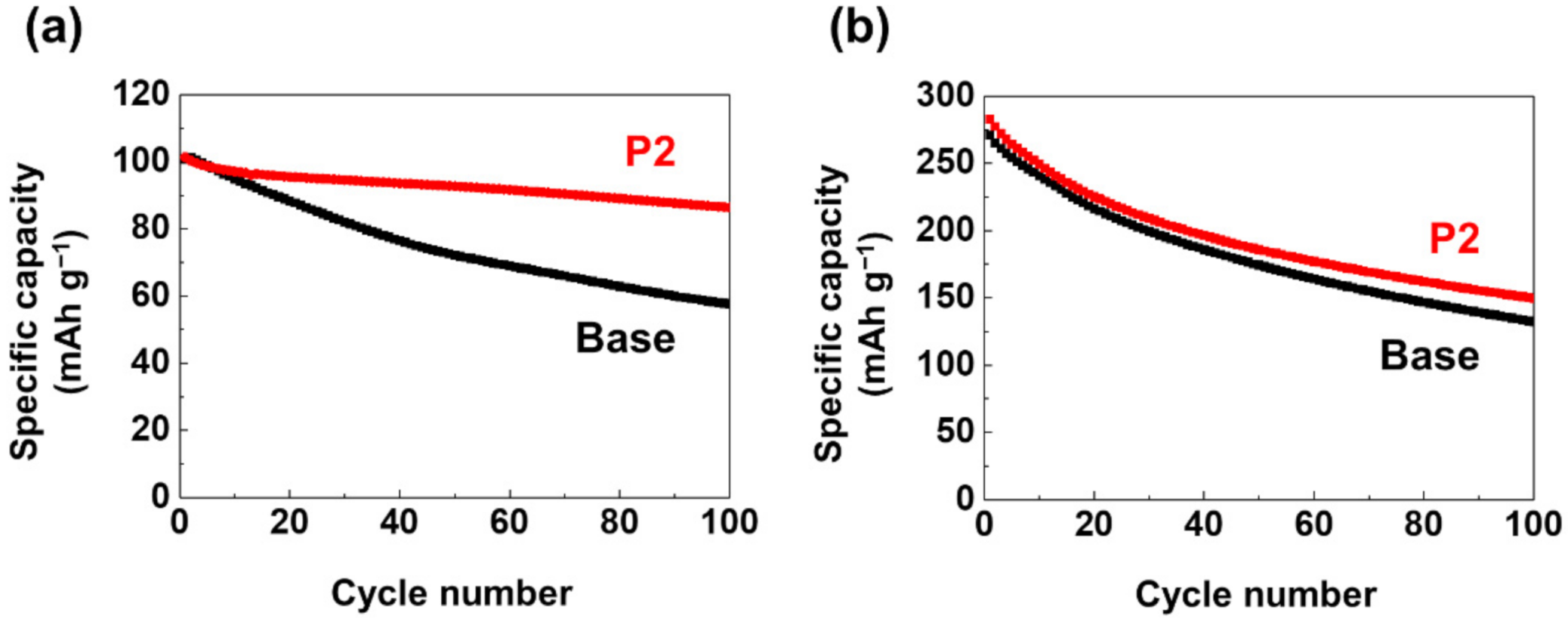
| Name 1 | Structure | Mn Concentration (ppm) |
|---|---|---|
| base | - | 0.345 |
| VC |  | 0.327 |
| FEC | 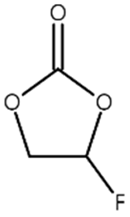 | 0.332 |
| AB |  | 0.319 |
| SN | 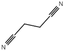 | 0.421 |
| P1 | 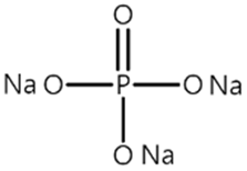 | 0.447 |
| P2 | 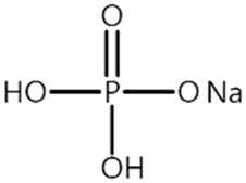 | 0.139 |
| P3 | 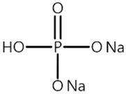 | 0.301 |
| SS1 | 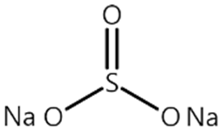 | 0.719 |
Publisher’s Note: MDPI stays neutral with regard to jurisdictional claims in published maps and institutional affiliations. |
© 2021 by the authors. Licensee MDPI, Basel, Switzerland. This article is an open access article distributed under the terms and conditions of the Creative Commons Attribution (CC BY) license (https://creativecommons.org/licenses/by/4.0/).
Share and Cite
Jo, M.; Park, S.-H.; Lee, H. Effects of a Sodium Phosphate Electrolyte Additive on Elevated Temperature Performance of Spinel Lithium Manganese Oxide Cathodes. Materials 2021, 14, 4670. https://doi.org/10.3390/ma14164670
Jo M, Park S-H, Lee H. Effects of a Sodium Phosphate Electrolyte Additive on Elevated Temperature Performance of Spinel Lithium Manganese Oxide Cathodes. Materials. 2021; 14(16):4670. https://doi.org/10.3390/ma14164670
Chicago/Turabian StyleJo, Minsang, Seong-Hyo Park, and Hochun Lee. 2021. "Effects of a Sodium Phosphate Electrolyte Additive on Elevated Temperature Performance of Spinel Lithium Manganese Oxide Cathodes" Materials 14, no. 16: 4670. https://doi.org/10.3390/ma14164670