Abstract
The complexity of torsional load, its three-dimensional nature, its combination with other stresses, and its disruptive impact make torsional failure prevention an ambitious goal. However, even if the problem has been addressed for decades, a deep and organized treatment is still lacking in the actual research landscape. For this reason, this review aims at presenting a methodical approach to address torsional issues starting from a punctual problem definition. Accidents and breaks due to torsion, which often occur in different engineering fields such as mechanical, biomedical, and civil industry are considered and critically compared. More in depth, the limitations of common-designed torsion-resistant structures (i.e., high complexity and increased weight) are highlighted, and emerge as a crucial point for a deeper nature-driven analysis of novel solutions. In this context, an accurate screening of torsion-resistant bio-inspired unit cells is presented, taking inspiration specifically from plants, that are often subjected to the torsional effect of winds. As future insights, the actual state of technology suggests an innovative transposition to the industry: these unit cells could be prominently implied to develop novel metamaterials that could be able to address the torsional issue with a multi-scale and tailored arrangement.
1. Introduction: The Destructive Power of Torsional Load and the Extended Interest in It
Failure due to torsional loads is a challenging and impactful issue to be addressed: it is commonly present in several fields and it has been observed and analyzed for more than two centuries.
Many authors have offered analysis methods for components subjected to torsion, which involves the use of approximations and simplifications due to the high complexity of the problem, characterized by a three-dimensional nature and seldom observed as purely applied, since it is often combined with bending, compression, and tension loads.
Furthermore, different approaches to find torsion-resistance solutions can be used. As an example, the problem could be faced through a classical mechanical analytical approach, as done by De Saint-Venant [1] in 1855, who implemented the analysis of a solid linear elastic homogeneous isotropic beam subjected to torsion. In the last century, different types of approaches have been exploited. In the first decades of the 1900s, the development of new technologies and components led to the exploitation of experimental analysis to face the torsional problem [2,3]. Indeed, for structures with complex geometries and heterogeneous materials, it was extremely difficult to define an exact mathematical model and to calculate its accurate solution. The limitation of these experimental approaches, however, was the low level of accuracy provided by the experimental equipment of those years [2]. In the 1960s, numerical methods, which exploit the application of a mathematical model capable of providing an approximation of the problem, have been implemented and used [4], overcoming the practical limitations of the testing apparatus. In the meantime, both the results of experimental and numerical analysis and the implementation of more complex mathematical models has allowed to confirm and further explore the proposed theoretical models [5], which have been refined and implemented for different types of components’ geometries [6] and complex materials such as concrete [7,8].
Starting from the 1980s, a disruptive new approach to solve the torsional problem has been proposed and includes the understanding and search of torsion-resistant natural structure strategies, thus engaging bio-inspiration [9,10,11,12,13,14].
In later years, even complex torsion-related problems such as non-linear analyses [15,16,17,18,19], dynamic analyses (for structures subjected to vibration or to fatigue) [20,21,22,23,24,25,26,27], and analysis of shell [28,29,30] and frame [31] structures have been addressed through analytical and numerical methods. Recently, solutions to the torsional issue focus on the development of novel meta-materials [32,33,34], which can also be bioinspired.
Despite the high variety of strategies used, this wide problem has not been fully and systematically approached yet, even though torsional load must be taken into consideration in the design of most components, whether being shafts or far more complex structures as in the case of ships, buildings, and aircrafts.
The evolution in approaching the torsional problem across years is presented in Figure 1, which reports the occurrence of publications dedicated to torsional analysis and a comparison with works dedicated to other more commonly applied loads such as tension, compression, and bending. It is immediately evident that the research devoted to the torsional problem is drastically limited in comparison with the more common loads, specifically because of the already mentioned reasons.
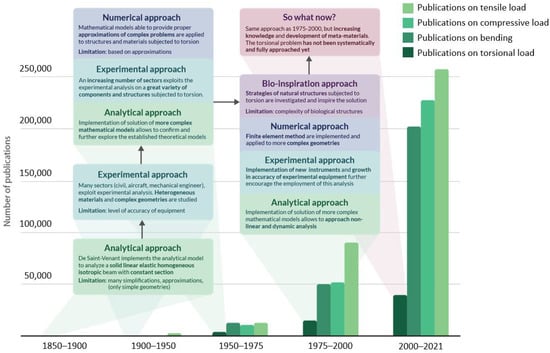
Figure 1.
The infographic presents the evolution in approaching the torsional problem across years and the occurrence of publications dedicated to torsional analysis from 1850 until today. For each period, the comparison of torsional works with the papers dedicated to other commonly applied loads (tension, compression, and bending) is reported. The green boxes focus on the evolution of the analytical approach and their limitations; the light-blue boxes refer to issues related to the experimental approach. Violet boxes are dedicated to observations concerning the numerical approach, while the purple rectangle concerns bio-inspiration strategies. In pink, the latest trends in addressing the torsional problem are reported.
The first point in order to comprehend and deal with the multi-faced and challenging aspects of this topic is to deeply analyze failure issues generated by torsion, being a pure or key contribution to failure.
1.1. Failure Due to Torsional Load
As above-mentioned, several fields are affected by torsional damage and even failure; a detailed analysis of sector-specific torsion-related issues is presented in this paragraph and schematized in Figure 2.
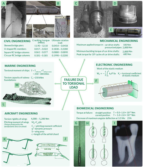
Figure 2.
Failure due to torsional load affect many fields of interest such as civil (A,B), mechanical (C–E), electronic (F), biomedical (G–I), aircraft (J,K), and marine (L,M) engineering. For each sector, specific torsional-related failures are reported.
An area of interest in which torsion is a matter of concern is civil engineering, where the aim is to better comprehend the behavior of buildings, bridges, or simply concrete beams under torsional static loads or dynamic loads, as in case of seismic events. In 1969, the theory of torsion in this sector has been described in more detail by Koll-Brunner and Basler [5], focusing on methods for the analysis of torsion of single-span or continuous members through the use of familiar tools for structural engineers. These solid, thin-walled, open or closed cross section structures are base elements for constructions, which even actually embrace torsion-related failures. For instance, as explained in the research of Kawashima et al. [18], piers of a skewed bridge could fail if subjected to extensive torsion damage (shown in Figure 2A) as a consequence of an earthquake. The damage was a direct effect of seismic activity and it could be clearly recognized that the torsional fatigue failure crack had a 45° inclination.
To be more precise, the load generated on bridge columns, foundations, walls, and in other civil structures is never steady and pure torsion, but usually a combination of different types of applied loads [16,35], characterized by a cyclic nature as analyzed by Kelly et al. [36]. Indeed, reinforced concrete beams, which undergo torsion failure, are a matter of concern even if strengthened with FRPs (fiber reinforced polymers), specifically designed for constructions. However, research on this topic is extremely limited [16], even though many authors have focused their research on beams under pure torsion condition, and specifically on both open section beams as in U-shaped thin-walled analyzed by Chen et al. [37] (Figure 2B), and closed section beams such as those described by Chariolis [38], Rao et al. [39], and Mondal et al. [16]. Again, in Figure 2B, the typical inclination of 45° of torsional fatigue failure cracks could be observed. Note that the first attempts in investigating concrete beams under torsion loads go back to 1900 [2]: in the first fifty years of the twentieth century, many suggestions to determine a reliable analytical criterion and methodology for concrete beams subjected to combined stress due to bending and torsion were proposed [2,7]. As reported by Fisher [2], who performed both experimental tests on cylindrical reinforced concrete beams, a suitable failure criterion in these conditions could be maximum stress theory. As further reported by Kemp et al. in 1971 [7], the major issue related to reinforced concrete subjected to torsional load is that the applied loading condition is neither homogeneous nor isotropic. This leads to a lack of mathematical rigor and thus uncertainty in the design phase. Another possible reason for the lack of studies on torsion in civil structures relies on the fact that buildings are usually assumed to be composed of articulated simple vertical or horizontal elements specifically arranged so that torsion could be eliminated in the structural analysis. In case it could not be completely neglected, torsion is usually included in the safety factor choice in the design phase. Not only methods to prevent torsion failure, but torsion failure mechanisms have also been analyzed with the aim to better recognize and characterize them. Indeed, as previously anticipated, one of the main issues related to torsion analysis is that it is difficult to isolate, recognize, and observe, usually combined with other types of load (i.e., bending [2,6,8]). These usually have shell geometries, characterized by a far more complex analysis of stresses and strains if compared to beams [5]. To approach this complexity, many authors have suggested tailored torsion analysis methods, as in the case of Kumari et al. [29], who analyzed the behavior of a conoidal shell. Similarly, Zheleznov et al. [17] focused their attention on the issues of the stability of elliptical cylindrical shells subjected to torsion and internal pressure and solve them from the analytical point of view in the case of nonlinear deformation.
Another field of interest is mechanical engineering, in which failures of shafts due to transmission of torque moments are frequently observed. Power transmission shafts are fundamental components of engines, turbines, and gearboxes, where torque resistance of shafts must be assured in both static and fatigue loading conditions [40]. In this regard, there are many fragmented analyses of solid and hollow shafts that failed due to torsional fatigue [41,42,43,44]. It has been observed that the effects of torsional fluctuating stress lead to unexpected failure, which shortens the predicted usage life: shafts are usually subjected to both torsion and bending loads, so failure may occur either at the maximum bending or torsional point. Considering the specific case of a crankshaft, failure occurs due to high stresses in a specific position along the component as a combination of maximal engine torque and maximal bending stress. Another remarkable fact is that cracks present in shafts that fail due to the combination of torsion and bending, as in the case of failed transmission shafts shown in Figure 2C–E, have the inclination of torsional fatigue failure cracks in brittle materials observed through visual macroscopic analysis, corresponding to 45°, as in the mentioned case of concrete beam failure cracks.
Thus, taking into consideration the failure due to torsional load in shafts, similar considerations could be extended to other sectors such as automotive [45,46,47,48,49], aerospace [43,45,50,51,52,53], agriculture [54,55,56], and energy production industry [57].
In the previous failure examples, the structures subjected to torsion were beams, with solid or hollow section, and shells. For the sake of completeness, it should be taken into consideration that the components’ behavior also strongly depends on their size and geometry. For instance, in the field of electronic engineering, rods with micro and nano dimensions present in micro-sensors and actuators are typically subjected to torsional vibrations [20,21] (Figure 2F). This dynamic condition could result in failure for rods with different shapes and sizes. This specific issue was investigated by Hassannejad et al. [21], who managed to prove the influence of geometry on the rods’ behavior under vibrational torsional loads.
Another peculiar example is related to the biomedical field, in which rotary endodontic instruments are commonly used. They have a very complex geometry and are highly subjected to torsional loads [58,59,60]. These hand-operated instruments are characterized by reduced dimensions, from hundreds of microns up to a millimeter [61], and have different cross-sectional shapes, as illustrated in Figure 2G,H [62], according to the specific function they are designed for. Improving torsion strength and torsion fatigue resistance in all these instruments could prevent failure, avoiding dangerous and complicated operations related to their unneeded extraction from teeth [63,64,65] (Figure 2I).
Another important field of interest is aircraft engineering, in which some shell and frame structures are subjected to torsional stresses: indeed, both fuselage [3,66,67,68,69] and wings [53,70,71] must fulfil geometric constraints to be as light as possible and face bending and torsional loads. To withstand these loads during take-off, flight, and landing, avoiding fatigue or static failure, these components must be specifically designed, with ad hoc features that guarantee increased stiffness and structural integrity. Considering wings, particular attention should be given to the actuation of aircraft flaps and slats (Figure 2J), which are strongly subjected to torsional loads during the flight phase [70]. In the case of fuselage panels, the main issue concerns the different possible deformation modes due to flexure–torsion, as shown in Figure 2K.
Additionally, even marine industry researchers have focused their attention on torsion, trying to identify the effect of shear stresses in thin-walled ships to avoid failure. Indeed, ship hulls [72] and ultra large container ships [73] are subjected to significant torsional moments, up to 300 kN∙m, due to both an improper distribution of cargo loading and fuel, and the presence of massive oblique waves (Figure 2L) [74]. In the case of reduced torsional stiffness, torsional loads could lead to failure of the ship, which could consequently cause environmental disasters as well explained by Shama [74] in his work, almost entirely dedicated to torsional load effects in ships. Moreover, frame, shell, and beam structures placed underneath the sea are also interested by torsional loads, as in the case of subsea foundations and piles or mooring applications analyzed by different researchers [31,75,76]. Considering the example of shallow foundations, a proper case study is the interaction between torsional and sliding loads, which might not be supported by structures such as oil pipeline end manifold and pipeline end termination systems (Figure 2M), as studied by McDonald et al. [31].
The impactful failures due to torsional load that have affected several engineering fields require a systematic discussion, starting from a comprehension of the complex torsional-related problem.
1.2. Torsion-Resistance: A Complex and Underestimated Issue
Torsional load effects have been preliminarily analytically considered since the 1850s, focusing on cylindrical elastic corpses described in the theory of Saint-Venant in “De la torsion des prismes” [77]. It has been known long before this theory that torsion is characterized by some peculiarities, which make its analysis very complex and challenging, even if this load is applied to cylindrical beams. Indeed, torsional load is not axial-symmetric and this means that it has a three-dimensional nature. For this reason, it is not possible to analyze torsion effects on components or design a torsion resistant structure without working in a complex three-dimensional space. According to this, in the case of components with more intricate geometries than cylindrical beams, the analysis of stresses and deformations is articulated to perform, as proven by the analysis and computational models of several researchers [4,5,25,74,78,79,80,81,82]. To sum up, considering a torque applied on structures with complex geometries such as those made of different interacting beams or thin walls, as in the case of the mentioned skirted foundations, the mechanical analysis of stresses and strains requires high computational cost and needs detailed meshing strategies.
Since the design of a component or a structure must pass through the optimization step, the complexity of calculating stresses and strains occurring due to the applied torsional loads is currently a limit. For instance, considering the case in which a lightweight structure is specifically required, it is not always possible to optimize the weight observing the structural constraints such as keeping the torsional rigidity constant [83].
This difficulty must be added to another issue related to torsion analysis, concerning the fact that this type of load is rarely the primary cause of failure: it is often combined with bending [83] and it frequently does not directly cause failure, even though it contributes to it. One of the actual challenges is to determine the contribution of torsion and to associate its effects in terms of strains and deformations.
Another reason that could explain the lack of research progresses in the optimization of torsional strength might be the complexity of analysis in the case of structures with very low or large size. On one hand, low size components, as in the case of rotary instruments, are difficult to observe and monitor under the application of load. On the other hand, structures such as aircraft wings and fuselages, buildings, bridges, ultra large container ships, and wind turbines are also difficult to analyze due to the presence of many multi-axial stress conditions.
2. Common-Designed Torsion-Resistant Structures
According to the specific application, structures and features with specific torsion resistant features have been designed and are reported in Table 1. Many of these structures have been commonly applied since the 1970s, as in the case of ship torsion boxes and torsional energy absorption devices, others have been introduced in the late nineties such as in the case of composite transmission power shafts. Some, such as the adaptive torsion wings, have only been conceptually modeled and lately investigated.

Table 1.
Common-designed torsion resistant structures. In the table, the fields of interest, a schematic of torsion-resistant components, their potentialities, and limitations are highlighted.
It can be observed that the common-designed torsion-resistant structures are characterized by some limitations. For instance, many of them are quite complex from the geometrical point of view: on one hand, this leads to the high complexity of numerical stress analysis and can affect the stress distribution, eventually causing local stress concentrations. On the other hand, the complexity of structures increases the costs of design and production of up to more than 250% if compared to conventional structures. The other main issue is weight increase, which could affect the performance of the components.
It is important to highlight the necessity to overcome these evident limitations through a transversal approach, considering the impressive power of nature-designed solutions [74].
3. Overcoming the Limitations of Traditional Structures from a Natural Perspective
3.1. Nature as a Source of Inspiration
Innovative solutions to face the torsional issue have recently been searched in nature, interrogated as a source of inspiration [74,93]. Many natural structures are subjected to torsional loads; some examples are tree trunks and wood cells and every bird and insect wing. Nature deals with torsion since the first birth species and the result is that there exist many systems in nature that develop torsion resistance through specific mechanisms and/or structural arrangements. For this reason, researchers consider nature as a qualified source of inspiration to develop torsion-resistant structures. Indeed, biomimicry and bio-inspiration are sciences based exactly on this concept [94], according to which scientists should respectively mime nature or let their research be inspired by it, lowering as much as possible the impact on the Earth and obtaining more sophisticated technologies, processes, and ecosystems [95,96]. Biological materials are able to optimally perform under different loads due to their complex and hierarchical structures, which go from macroscale to microscale [97]. Indeed, biological structures vary at different levels [98] and the interaction between them could provide specific torsional properties to the system as a whole. As an example, the complex hierarchical structure of wood is illustrated in Figure 3 and is characterized by more than five levels of hierarchy, as described in International Standard ISO 18457 (2016) on biomimetics [99,100]. Note that the multi-layer concentric cylindric structure of wood cells provide torsion resistance [101] and that the helicoidal transitions at the microscale avoid discontinuities in the change of properties between different levels of the entire structure [102].
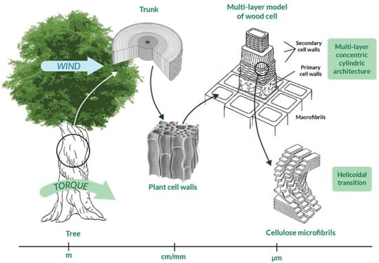
Figure 3.
Hierarchical structure of wood from macroscale to microscale. Multi-layer concentric cylindric architecture and helicoidal transition are peculiarities that allow for torsion resistance and a progressive transition of properties, respectively.
As explained in depth by Huang et al. [103], the analysis of biological materials is quite intricate from the point of view of the computational analysis, also considering that some properties could derive from the interaction between structures at different levels of hierarchy [104]. To shed some light on this complexity, a characterization through multi-scale computational models can be taken into consideration [105,106].
3.2. Torsional Load in Nature: The Need of a Specific Problem Definition
As mentioned in Section 3.1, in order to overcome the limitations identified in traditional-designed torsion resistant structures, an interesting key could be bio-inspiration. However, to find an optimized solution to the torsion complex issue, a methodical approach should first be implemented. Indeed, natural structures that proved to have specific properties and functionalities could be investigated through characterization at various levels of the hierarchical structure, allowing the property of interest to be isolated [107]. Process models to approach bioinspired research have been proposed and analyzed, as also pointed out by Fayemi et al. [99] and Katiyar et al. [94], who suggested a unified problem-driven process (Figure 4). Taking into consideration different levels of abstraction, the problem can be divided in two phases: for each of them there are four steps that allow the biomimetic complex issue to be solved.
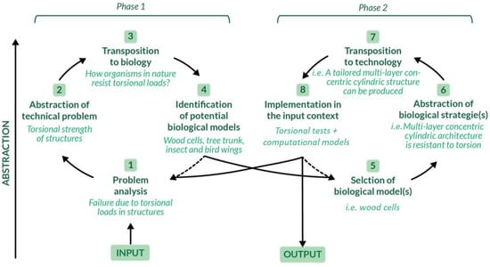
Figure 4.
A schematization of the process model of biomimetics to address the torsional issue is presented. It is divided into two phases and eight steps: each of these steps takes advantage from specific tools such as problem analysis, abstraction, transposition, etc. [99,108]. Adapted with permission from [99].
To develop torsional bioinspired structures, the problem analysis should be performed first (i.e., the description of the problem related to torsion resistance). Examples of problem analysis are reported in Section 1.1, together with a detailed collection of components and structures commonly subjected to torsional damage or failure. There are many fields of interest in which the development of an optimal torsion resistant structure might lead to an improvement in conventionally designed engineering components. For this reason, potentially prominent biological models were analyzed and critically compared.
3.3. Torsion-Resistant Nature-Inspired Structures: Biomimetic Unit Cells
In order to develop bioinspired innovative structures and prevent failures and damage due to torsional loading, some potential unit cells and geometries of biological structures were considered for the analysis and are schematized in Table 2, based on the screening in the abstraction tool [99]. First, some peculiar structures are present in ivory, a highly non-isotropic material with complex three-dimensional structures. Indeed, in every tusk, a core of dentine, usually referred to as ivory, is present: it is made of a matrix of micrometric cuboid [109] particles in a ground substance that contains dentinal tubules. These are cylinders aligned in sheets forming micro laminae, which are generally axially oriented, but could even be radially disposed, angled to the forming face or wrapped to form a helix [110]. Note that dentinal tubules might be curled into waves or could be straight and within micro laminae, they can be radial and angled to the axis (Table 2, first unit cell), specifically varying torsion-resistant properties. Finally, dentinal tubules may have the same orientation in adjacent micro-laminae, or orientation may change in the presence of a helicoidal pattern, obtaining a multi-layer concentric cylindrical architecture that is also present in the osteons of bones [111]. Considering that every kind of ivory has evolved its own structure to answer different needs such as increased strength and toughness [109], optimized bending and torsion resistant structure could be inspired by ivory. Many types of tusks could be investigated, as undertaken by Locke [109], who showed the macroscopical features of tusks. In the same study, microscopical details of different species of ivory such as dentine tubule arrangement in micro laminae, were identified. Focusing on the structure of narwhal tusk, a macroscopic life-handed helix spiral could be recognized [112]: it is characterized by an angle of inclination of the spiral arc of 66.88 ± 0.61° [113]. Mechanical properties of narwhal tusk have been examined by some studies [13,114], which established that tusk dentine is not a homogeneous material and is characterized by anisotropic properties. No specific studies related to the torsional test of narwhal tusk have been conducted, but an analogous helicoidal structure has been tested under torsion, exhibiting prominent behavior as in the case of a helix-reinforced composite, as reported by Porter et al. [86].
Table 2.
Torsion-resistant biomimetic unit cells are selected, the biological source, and the schematic of the structure is reported. Additionally, specific torsion-resistant features are highlighted, in accordance with the performed mechanical/numerical tests.
Another inspiring solid structure is the multi-layer concentric cylindrical cell wall architecture of plants [101] and bone osteons [115,116,117] (Table 2, second unit cell): stiff helicoidal micro-fibers are arranged parallel to each other in every microfibril thick lamellae [14,102,118], each one oriented according to a specific direction with respect to the cell axis. That direction is referred to as the microfibril or winding angle, in the range of 0 ± 90° [101], and it is the angle between a lamella and the subsequent one. This structure allows wood and bones to obtain superior mechanical properties to both bending and torsion through the optimization of the plies and angles combination [117]. Helicoidal layers of fibers arranged according to a multi-layer concentric cylindrical architecture are widely diffused in other recently investigated biological materials such as in insect cuticle and skeleton of glass sponges [119]. It is interesting to point out that helicoidal cell walls might be characterized by a far more complex texture: it might be formed by a mechanism based on geometrical considerations, which witnesses that the cell is equipped with intrinsic tools to generate a large variety of load-bearing textures [118]. Macroscopic plant structures are also characterized by helicoidal features; these structures increase torsion resistance, which is useful when wind forces are present. Indeed, in Figure 3, the mechanism according to which the wind can cause torsional load on a tree [120] is schematized; note that stem, roots, and soil altogether resist the generated torque. In fact, as explained by Skatter in his study [121], trees are mainly subjected to torsion due to wind forces, especially when they have asymmetric crowns: few decimeters of asymmetry can cause shear failure of the stem.
To avoid this, it has been demonstrated that spiral grain (Table 2, third unit cell) in the direction of wind-induced torque increases the bending and torsion strength of the stem and thus a beneficial configuration is obtained [121,122]. As a matter of fact, a spiral grain stem bends and twists more than a straight-grain stem when exposed to strong wind: through this mechanism of deformation, it offers less wind resistance and is less likely to break. A similar multi-layer architecture could be found in reinforcement geodetics [123], which are geometries on curved surfaces given by geodesic lines of which there are four kinds: the annular model, the single helicoidal thickening model, the double helicoidal thickening model, and the straight lines parallel and perpendicular to the axis mode. In the annular model, a series of annuli is arranged in parallel planes and is perpendicular to the axis of the cylinder, decreasing the buckling possibility. In nature, this reinforcement type is present in both plant-cells [123] and bird bones [90], where annuli are known as ridges, that, however, do not have a disruptive impact on the torsion-resistance of the entire structure. In the single helicoidal thickening model, thickenings have the function of strengthening the biological walls and preventing their collapse. For example, helical cell-wall thickenings observed in the root cortex cells of many Asplenium species mechanically stabilize the cortex tissue [124]. Helicoidal structures are commonly found in the peripheral body locations of plants and animals to prevent surface failure: indeed, if the beam is bent or twisted, the greatest stresses are concentrated on the surface, so an external strengthening mechanism could prevent failure. Furthermore, it has been well established that helicoidal components act as shearing force protection, that is, a specific point of interest for the purpose of this review [102]. One proof of this is the helicoidal arrangement of tension-resisting fibers observed in the stem of young herbaceous plants such as sunflowers. They provide wrapping for flatworms and roundworms: their outer membrane might be characterized by two different fiber arrangements. Fibers might run lengthwise and circumferentially or run helically, with left and right-hand helices, determining utterly different responses to the various torsional stresses the structures might encounter, as described by Vogel [125] and Neville [102]. Specifically, the helically reinforced model smoothly deforms responding to both tension and compression, but strongly resist torsional stresses: according to Vogel [125], the sets of left and right-handed helically arranged fibers resist twist in all directions. The value of deformation and torsional strength depends on the material that characterizes the structure. A fundamental parameter for helically reinforced surface membranes, and more in general helical torsion-resistant systems, is the “fiber angle”. It is the angle forming between the fibers and the long axis of the cylinder, and explains the relationship between the structure and its mechanical behavior, often derived with the aid of computational models [51,86,101,114,116,121,126,127,128].
A different example of a natural torsion-resistant unit cell in which helices are present is Bouligand’s structure [129] (Table 2, fourth unit cell), largely diffused in most arthropod cuticle. Indeed, the arthropod epidermal cells are characterized by a periodic architecture, with a helicoidal stacking of unidirectional chitin–protein fibrils set in an amorphous matrix [102,130]. The name of this structure comes from Bouligand, who dedicated his studies on the description of this twisted fibrous arrangement, which has then been largely observed in biological materials and tested under torsion [129]. Typically, Bouligand’s model could be recognized by a characteristic parabolic pattern that can be geometrically interpreted as an oblique section visualization of the layered and twisted structure resembling plywood [131], where consecutive layers of fibrils have a constant angle of twisting.
Bouligand’s structure has been proven to have a remarkable fracture toughness [140], well beyond its constituents, thanks to a combination of two main propagation modes controlled by that arrangement of chitin–protein: crack twisting and bridging (Table 2). Indeed, before the fracture begins, the twisted plywood allows reorientation and deformation of fibers in response to torsional loadings [144]. In other words, Bouligand’s structure ductility and toughness are biologically designed to prevent fracture through changes in the structural arrangement. Furthermore, Bouligand’s structure has exceptional stiffness and hardness [143,145,146] and, similar to that discussed for ivory, optimized bending and torsion resistance can be inspired by this structure, as proven by works such as the one by Nikolov et al. on high-performance composite structures [141]. To provide an idea of the wide diffusion of this architecture in nature, it is worth mentioning that arthropods are a kind of invertebrate animal that covers more than half the classified species [138], proving that their biological structures, and specifically their torsion-resistant properties, are highly performing and adaptable [129,130,139,140,141,142,143,147,148,149]. Arthropods include insects, arachnids, myriapods, and crustaceans that have a cuticle with a twisted plywood. Furthermore, Bouligand’s structure can be associated with micro- and nanoscale architecture (i.e., cholesteric liquid crystal), which, as explained by Mitov [150], are omnipresent in nature: chitin, cellulose, collagen, and silk are characterized by the Bouligand arrangement [102].
4. From Nature to Novel Materials: Torsion-Resistant Metamaterials
Eventually, nature-inspired structures have been exploited in the design of novel metamaterials that are able to actively address the torsion-resistance issue with innovative and customized solutions. Following the problem-driven approach defined in Section 3.2, phase 2 is now faced and the biological strategies abstracted from natural torsion-resistant unit cells are transposed to technology and tested.
Metamaterials are characterized by properties not simply given by their composition, but arising from their structure [34]; they are usually assembled starting from one or more basic unit elements that repeat themselves, forming a clinical pattern [151]. An example is the metamaterial conceived by Zhong et al. [33], which was able to convert axial compression (or tension) into torsion: the unit cell, the following metamaterial, and the final tested specimen are illustrated in Figure 5A. Note that the unit cell of this material is characterized by an arrangement of rods, which resembles the helical structures described in Section 3.3. The proposed design allows for a promising peak value of 16.2° of torsion angle to be reached. Possible applications of this metamaterial are wave converters, able to transform shear waves into longitudinal waves and vice versa, or morphing structures in aircraft and aerospace engineering [33].
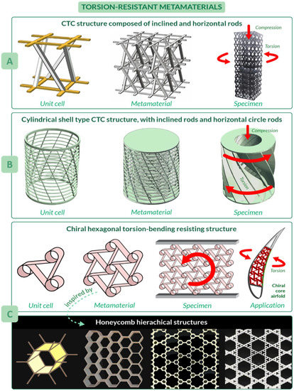
Figure 5.
Torsion-resistant metamaterials. (A) Compression–torsion–conversion (CTC) structure composed of inclined and horizontal rods. (B) Cylindrical shell type CTC structure. (C) Chiral hexagon torsion-bending resistant structure.
Another compression-torsion-conversion (CTC) metamaterial has been proposed by Wang et al. [32], which focused their attention not only on the properties of the final structure, but also on the main problem of metamaterials such as inefficient use of space. Their work introduces a cylindrical metamaterial, increasing the capability of compression and torsion resistance [32]. Its unit cell has inclined and horizontal circle rods, which resembles the helical and annular features of natural unit cells, respectively (Figure 5B). The most crucial benefit of this structure is the tailored torsion resistance coming from the relationship between rod inclination angle and the torsion angle of the rotation spring: the larger the rod inclination angle and slenderness ratio, the larger the torsion angle. The metamaterial consists of three of the cylindrical shells, differing in radius, arranged one inside the other. Since manufacturing of these structures, also known as rotation springs, is quite problematic, a continuous structure with curved surfaces has been proposed for tests. Applications of these metamaterials include structures of machinery and vehicles.
Considering the need to design lightweight components, promising metamaterials have been inspired by honeycombs. As shown by Haghpanah et al. [152], from the basic concept of hexagonal honeycomb, more complex hierarchical structures with an improved efficiency could be developed, as in the case of self-similar hierarchical honeycombs shown in Figure 5C. An example of structure inspired by honeycombs is the morphing airfoil designed by Bettini et al. [153,154], where a composite chiral element, which resembles honeycomb hexagons and spirals (largely diffused in nature [123,155,156,157]), was used in the core of the airfoil to resist torsion and bending during flight. To be more precise, this metamaterial can improve morphing performances by increasing the maximum allowable displacement, which can reach in tension up to 12% of cell dimension and about 30% in compression.
5. Conclusions and Future Perspectives
Failure of components due to torsional load is an impactful issue that has been addressed across the years, starting from a simplified analytical approach and reaching time-demanding computational simulations. However, the complexity of the problem, its three-dimensional nature, the combination of torsional load with other kinds of stresses (i.e., compression, bending or tension) make its systematic analysis particularly hard.
In order to overcome these limitations, a methodical approach was proposed in this review, starting from a punctual analysis of the problem. Several torsional failures have been deeply investigated and categorized in different fields of interest. Common-designed solutions to increase torsional resistance are critically compared and their drawbacks (i.e., high complexity and weight) are the preparatory point for a deeper nature-driven analysis.
For this reason, nature is considered as a mine of disruptively novel ideas: helicoidal laminae cylinders, multi-layer concentric cylindric architectures, helically externally reinforced cylinders, cylinders with external helical grains, and Bouligand’s structures have been identified as prominent candidates to address the torsional problem. These architectures are commonly found in both plants and animals, which should resist torsional load during their life-cycle without deteriorating their mechanical characteristics.
After this precise screening, a transposition to technology was proposed: biological strategies commonly implied by torsion-resistant bio-inspired unit cells are exploited in novel metamaterials, which present a multi-scale specific arrangement to address the torsional issue. Their properties do not come solely from the characteristics of the base materials, but from their newly arranged structure. Their precise torsion-resistant bio-inspired shape, combined with multi-scale architecture and tailored orientation of the inner fibers make them future prominent candidates to effectively address the design drawbacks encountered in traditional torsion-resistant structures.
Author Contributions
Literature search, F.B. and G.M.; Data analysis, F.B. and G.M.; Draft/critical review of the work, F.B., G.M. and L.M.V.; Idea for the article, F.B. and L.M.V. All authors have read and agreed to the published version of the manuscript.
Funding
This research received no external funding.
Institutional Review Board Statement
Not applicable.
Informed Consent Statement
Not applicable.
Data Availability Statement
Not applicable.
Conflicts of Interest
The authors declare no conflict of interest.
References
- Sternberg, E. On Saint-Venant’s principle. Q. Appl. Math. 1954, 11, 393–402. [Google Scholar] [CrossRef]
- Fisher, D. The strenght of concrete in combined bending torsion. Univ. Lond. 1950, 61, 1509–1522. [Google Scholar] [CrossRef]
- Argyris, J.H. Flexure-Torsion Failure of Panels: A Study of Instability and Failure of Stiffened Panels under Compression when Buckling in Long Wavelengths. Aircr. Eng. Aerosp. Technol. 1954, 26, 213–219. [Google Scholar] [CrossRef]
- Barsoum, R.S.; Gallagher, R.H. Finite element analysis of torsional and torsional–flexural stability problems. Int. J. Numer. Methods Eng. 1970, 2, 335–352. [Google Scholar] [CrossRef]
- Kollbrunner, C.F.; Basler, K. Torsion in Structures; Springer: Berlin/Heidelberg, Germany, 1969. [Google Scholar] [CrossRef]
- Lampert, P.; Thürlimann, B. Ultimate Strength and Design of Reinforced Concrete Beams in Torsion and Bending. In Ultimate Strength and Design of Reinforced Concrete Beams in Torsion and Bending/Résistance et dimensionnement des poutres en béton armé soumises à la torsion et à la flexion/Bruchwiderstand und Bemessung von Stahlbetonbalken unter Torsion und Biegung; Birkhäuser: Basel, Switzerland, 1972; Volume 42, pp. 107–131. [Google Scholar] [CrossRef]
- Kemp, E.L.; Sozen, M.A.; Siess, C.P. Torsion in Reinforced Concrete. 1961. Available online: https://www.ideals.illinois.edu/handle/2142/13762 (accessed on 16 July 2021).
- Elfren, L.; Karlsson, I.; Losberg, A. Torsion-Bending-Shear-Interaction for Concrete Beams. ASCE J. Struct. Div. 1974, 100, 1657–1676. [Google Scholar] [CrossRef]
- Renson, C.E.; Braden, M. Experimental determination of the rigidity modulus, poisson’s ratio and elastic limit in shear of human dentine. Arch. Oral Biol. 1975, 20, 43–45. [Google Scholar] [CrossRef]
- Renson, C.E.; Boyde, A.; Jones, S.J. Scanning electron microscopy of human dentine specimens fractured in bend and torsion tests. Arch. Oral Biol. 1974, 19, 447-IN5. [Google Scholar] [CrossRef]
- Ennos, A.R. The Importance of Torsion in the Design of Insect Wings. J. Exp. Biol. 1988, 140, 137–160. [Google Scholar] [CrossRef]
- Jackson, A.P.; Vincent, J.F.V.; Turner, R.M. The mechanical design of nacre. Proc. R. Soc. London Ser. B Biol. Sci. 1988, 234, 415–440. [Google Scholar] [CrossRef]
- Brear, K.; Currey, J.D.; Kingsley, M.C.S.; Ramsay, M. The mechanical design of the tusk of the narwhal (Monodon nonoceros: Cetacea). J. Zool. 1993, 230, 411–423. [Google Scholar] [CrossRef]
- Kubler, H. Function of Spiral Grain in Trees; Springer: Berlin/Heidelberg, Germany, 1991; Volume 5. [Google Scholar] [CrossRef]
- Huang, H.; Han, Q. Nonlinear buckling of torsion-loaded functionally graded cylindrical shells in thermal environment. Eur. J. Mech. A/Solids 2010, 29, 42–48. [Google Scholar] [CrossRef]
- Rakoczy, A.M.; Asce, A.M.; Otter, D.E.; Asce, M.; Malone, J.J.; Farritor, S. Railroad Bridge Condition Evaluation Using Onboard Systems Introduction and Motivation. 2016. Available online: https://ascelibrary.org/doi/abs/10.1061/%28ASCE%29BE.1943-5592.0000881 (accessed on 16 July 2021).
- Zheleznov, L.P.; Kabanov, V.V.; Boiko, D.V. Nonlinear Deformation and Stability of Discrete-Reinforced Elliptical Cylindrical Composite Shells under Torsion and Internal Pressure. Russ. Aeronaut. 2018, 61, 175–182. [Google Scholar] [CrossRef]
- Tirasit, P.; Kawashima, K. Effect of nonlinear seismic torsion on the performance of skewed bridge piers. J. Earthq. Eng. 2008, 12, 980–998. [Google Scholar] [CrossRef]
- Farahani, D.; Behnamfar, F.; Sayyadpour, H. Effect of pounding on nonlinear seismic response of torsionally coupled steel structures resting on flexible soil. Eng. Struct. 2019, 195, 243–262. [Google Scholar] [CrossRef]
- Narendar, S.S.; Ravinder, S.G. Strain gradient torsional vibration analysis of micro/nano rods. Int. J. Nano Dimens. 2012, 3, 1–17. [Google Scholar] [CrossRef]
- Hassannejad, R.; Hosseini, S.A.; Alizadeh-Hamidi, B. Influence of non-circular cross section shapes on torsional vibration of a micro-rod based on modified couple stress theory. Acta Astronaut. 2021, 178, 805–812. [Google Scholar] [CrossRef]
- Ismail, M. New approach to seismic-resistant design and structural torsion mitigation. Eng. Struct. 2020, 207, 110092. [Google Scholar] [CrossRef]
- Fonte, M.A.; Freitas, M.M. Semi-elliptical fatigue crack growth under rotating or reversed bending combined with steady torsion. Fatigue Fract. Eng. Mater. Struct. 1997, 20, 895–906. [Google Scholar] [CrossRef]
- Barnes, M.R.; Adriaenssens, S.; Krupka, M. A novel torsion/bending element for dynamic relaxation modeling. Comput. Struct. 2013, 119, 60–67. [Google Scholar] [CrossRef]
- Sofiyev, A.H.; Schnack, E. The stability of functionally graded cylindrical shells under linearly increasing dynamic torsional loading. Eng. Struct. 2004, 26, 1321–1331. [Google Scholar] [CrossRef]
- Park, S.Y.; Cheung, G.S.P.; Yum, J.; Hur, B.; Park, J.K.; Kim, H.C. Dynamic torsional resistance of nickel-titanium rotary instruments. J. Endod. 2010, 36, 1200–1204. [Google Scholar] [CrossRef]
- Peters, O.A.; Barbakow, F. Dynamic torque and apical forces of ProFile.04 rotary instruments during preparation of curved canals. Int. Endod. J. 2002, 35, 379–389. [Google Scholar] [CrossRef]
- Wan, F.Y.M. Finite Axial Extension and Torsion of Elastic Helicoidal Shells. In Asymptotic and Computational Analysis; CRC Press: Boca Raton, FL, USA, 2020; pp. 491–516. [Google Scholar] [CrossRef]
- Kumari, S.; Chakravorty, D. On the bending characteristics of damaged composite conoidal shells—A finite element approach. J. Reinf. Plast. Compos. 2010, 29, 3287–3296. [Google Scholar] [CrossRef]
- Erduran, E.; Ryan, K.L. Effects of torsion on the behavior of peripheral steel-braced frame systems. Earthq. Eng. Struct. Dyn. 2011, 40, 491–507. [Google Scholar] [CrossRef]
- McDonald, S.; Suroor, H.; Malachowski, J.; Wang, Q.; Qi, X. Analysis of subsea foundations subjected to significant torsion. In Proceedings of the International Conference on Offshore Mechanics and Arctic Engineering—OMAE, San Francisco, CA, USA, 8–13 June 2014; Volume 3. [Google Scholar] [CrossRef]
- Wang, Y.B.; Liu, H.T.; Zhang, Z.Y. Rotation spring: Rotation symmetric compression-torsion conversion structure with high space utilization. Compos. Struct. 2020, 245, 112341. [Google Scholar] [CrossRef]
- Zhong, R.; Fu, M.; Chen, X.; Zheng, B.; Hu, L. A novel three-dimensional mechanical metamaterial with compression-torsion properties. Compos. Struct. 2019, 13, 36416–36425. [Google Scholar] [CrossRef]
- Sihvola, A. Metamaterials: A Personal View. Radioengineering 2009, 18, 90–94. [Google Scholar]
- Prakash, S.; Belarbi, A.; You, Y.M. Seismic performance of circular RC columns subjected to axial force, bending, and torsion with low and moderate shear. Eng. Struct. 2010, 32, 46–59. [Google Scholar] [CrossRef]
- Kelly, J.M.; Skinner, R.I.; Heine, A.J. Mechanisms of Energy Absorption in Special Devices for Use in Earthquake Resistant Structures. Bull. N. Z. Soc. Earthq. Eng. 1972, 5, 63–73. [Google Scholar] [CrossRef]
- Chen, S.; Diao, B.; Guo, Q.; Cheng, S.; Ye, Y. Experiments and calculation of U-shaped thin-walled RC members under pure torsion. Eng. Struct. 2016, 106, 1–14. [Google Scholar] [CrossRef]
- Chalioris, C.E. Analytical model for the torsional behaviour of reinforced concrete beams retrofitted with FRP materials. Eng. Struct. 2007, 29, 3263–3276. [Google Scholar] [CrossRef]
- Rao, T.D.G.; Rama Seshu, D. Analytical model for the torsional response of steel fiber reinforced concrete members under pure torsion. Cem. Concr. Compos. 2005, 27, 493–501. [Google Scholar] [CrossRef]
- Niemann, G.; Winter, H.; Höhn, H.W. Manuale degli Organi delle Macchine; Tecniche Nuove: Milan, Italy, 2006. [Google Scholar]
- Arisoy, C.F.; Başman, G.; Şeşen, M.K. Failure of a 17-4 PH stainless steel sailboat propeller shaft. Eng. Fail. Anal. 2003, 10, 711–717. [Google Scholar] [CrossRef]
- Zambrano, O.A.; Coronado, J.J.; Rodríguez, S.A. Failure analysis of a bridge crane shaft. Case Stud. Eng. Fail. Anal. 2014, 2, 25–32. [Google Scholar] [CrossRef]
- Infante, V.; Silva, J.M.; Silvestre, M.A.R.; Baptista, R. Failure of a crankshaft of an aeroengine: A contribution for an accident investigation. Eng. Fail. Anal. 2013, 35, 286–293. [Google Scholar] [CrossRef]
- Bhaumik, S.K.; Rangaraju, R.; Parameswara, M.A.; Venkataswamy, M.A.; Bhaskaran, T.A.; Krishnan, R.V. Fatigue failure of a hollow power transmission shaft. Eng. Fail. Anal. 2002, 9, 457–467. [Google Scholar] [CrossRef]
- Bayrakceken, H.; Tasgetiren, S.; Yavuz, I. Two cases of failure in the power transmission system on vehicles: A universal joint yoke and a drive shaft. Eng. Fail. Anal. 2007, 14, 716–724. [Google Scholar] [CrossRef]
- Chowdhuri, M.A.K.; Hossain, R.A. Design analysis of an automotive composite drive shaft. Int. J. Eng. Technol. 2010, 2, 45–48. [Google Scholar]
- Leelavathi, A.V.R. Design & Analysis of an Automotive Composite Drive Shaft. Int. J. Res. Eng. Sci. 2020, 8, 24–28. [Google Scholar]
- An Investigation on Hybrid Composite Drive Shaft for Automotive Industry. Int. J. Mech. Mater. Eng. 2019, 13, 258–264. [CrossRef]
- Vogwell, J. Analysis of a vehicle wheel shaft failure. Eng. Fail. Anal. 1998, 5, 271–277. [Google Scholar] [CrossRef]
- Freitas, M.; Infante, V.; Baptista, R. Failure analysis of the nose landing gear axle of an aircraft. Eng. Fail. Anal. 2019, 101, 113–120. [Google Scholar] [CrossRef]
- Hao, W.; Liu, Y.; Huang, X.; Liu, Y.; Zhu, J. A unit-cell model for predicting the elastic constants of 3d four directional cylindrical braided composite shafts. Appl. Compos. Mater. 2017, 25, 619–633. [Google Scholar] [CrossRef]
- Shokrieh, M.M.; Hasani, A.; Lessard, L.B. Shear buckling of a composite drive shaft under torsion. Compos. Struct. 2004, 64, 63–69. [Google Scholar] [CrossRef]
- Pang, H.; Yu, T.; Song, B. Failure mechanism analysis and reliability assessment of an aircraft slat. Eng. Fail. Anal. 2016, 60, 261–279. [Google Scholar] [CrossRef]
- Khalid, M.; Smith, J.L. Axle torque distribution in 4WD tractors. J. Terramech. 1981, 18, 157–167. [Google Scholar] [CrossRef]
- Ryu, I.H.; Kim, D.C.; Kim, K.U. Power efficiency characteristics of a tractor drive train. Trans. Am. Soc. Agric. Eng. 2003, 46, 1481–1486. [Google Scholar] [CrossRef]
- Nanaware, G.K.; Pable, M.J. Failures of rear axle shafts of 575 DI tractors. Eng. Fail. Anal. 2003, 10, 719–724. [Google Scholar] [CrossRef]
- Zhang, Z.; Yin, Z.; Han, T.; Tan, A.C.C. Fracture analysis of wind turbine main shaft. Eng. Fail. Anal. 2013, 34, 129–139. [Google Scholar] [CrossRef]
- Câmara, A.S.; de Castro Martins, R.; Viana, A.C.D.; de Toledo Leonardo, R.; Buono, V.T.L.; de Azevedo Bahia, M.G. Flexibility and Torsional Strength of ProTaper and ProTaper Universal Rotary Instruments Assessed by Mechanical Tests. J. Endod. 2009, 35, 113–116. [Google Scholar] [CrossRef]
- Turpin, Y.L.; Chagneau, F.; Vulcain, J.M. Impact of two theoretical cross-sections on torsional and bending stresses of nickel-titanium root canal instrument models. J. Endod. 2000, 26, 414–417. [Google Scholar] [CrossRef]
- Jamleh, A.; Almedlej, R.; Alomar, R.; Almayouf, N.; Alfadley, A.; Alfouzan, K. Evidence for reduced torsional resistance of rotary files under curved position. Saudi Dent. J. 2020, 33. in press. [Google Scholar] [CrossRef]
- Best, S.; Watson, P.; Pilliar, R.; Kulkarni, G.G.K.; Yared, G. Torsional fatigue and endurance limit of a size 30.06 ProFile rotary instrument. Int. Endod. J. 2004, 37, 370–373. [Google Scholar] [CrossRef]
- Torabinejad, M.; Fouad, A.; Shabahang, S. Endodontics: Principles and Practice; Elsevier: Beijing, China, 2015. [Google Scholar]
- Alomairy, K.H. Evaluating Two Techniques on Removal of Fractured Rotary Nickel-Titanium Endodontic Instruments from Root Canals: An In Vitro Study. J. Endod. 2009, 35, 559–562. [Google Scholar] [CrossRef] [PubMed]
- Van der Vyver, P.J.; Vorster, M.; Jonker, C.H. Modern considerations when approaching fractured endodontic instruments—Part 2: A review of the literature and clinical techniques. S. Afr. Dent. J. 2020, 75, 564–574. [Google Scholar] [CrossRef]
- Bürklein, S.; Donnermeyer, D.; Wefelmeier, M.; Schäfer, E.; Urban, K. Removing fractured endodontic NiTi instruments with a tube technique: Influence of pre-treatment with various agents on adhesive forces in vitro. Materials 2020, 13, 144. [Google Scholar] [CrossRef] [PubMed]
- Schijve, J. Multiple-Site Damage in Aircraft Fuselage Structures. Fatigue Fract. Eng. Mater. Struct. 1995, 18, 329–344. [Google Scholar] [CrossRef]
- Easa ABCD-FL-57-00—Wing Load Calculation—v1 08.03.16. 2016. Available online: https://it.scribd.com/document/505213057/ABCD-FL-57-00-Wing-Load-Calculation-v1-08-03-16 (accessed on 16 July 2021).
- Dehm, S.; Wurzel, D. Fast, in-situ repair of aircraft panel components. J. Aircr. 1989, 26, 476–481. [Google Scholar] [CrossRef]
- Boitsov, B.V.; Gavva, L.M.; Endogur, A.I.; Firsanov, V.V. Stress-Strain State and Buckling Problems of Structurally-Anisotropic Aircraft Panels Made of Composite Materials in View of Production Technology. Russ. Aeronaut. 2018, 61, 524–532. [Google Scholar] [CrossRef]
- Bennett, J.W.; Mecrow, B.C.; Jack, A.G.; Atkinson, D.J.; Sewell, C.; Mason, G.; Sheldon, S.; Cooper, B. Choice of drive topologies for electrical actuation of aircraft flaps and slats. IEE Conf. Publ. 2004, 1, 332–337. [Google Scholar] [CrossRef]
- Goland, M. A Study of the Bending-Torsion Aeroelastic. J. Aeronaut. Sci. 1949, 16, 389–396. [Google Scholar] [CrossRef]
- Paik, J.K.; Thayamballi, A.K.; Pedersen, P.T.; Il Park, Y. Ultimate strength of ship hulls under torsion. Ocean Eng. 2001, 28, 1097–1133. [Google Scholar] [CrossRef]
- Wang, Q.; Wang, C.; Wu, J.; Wang, D. Experimental and numerical investigations of the ultimate torsional strength of an ultra large container ship. Mar. Struct. 2020, 70, 102695. [Google Scholar] [CrossRef]
- Shama, M. Torsion and shear stresses in ships. Torsion Shear Stress. Ships 2010, 1, 1–277. [Google Scholar]
- Suroor, H.; Hossain, J. Effect of torsion on suction piles for subsea and mooring applications. In Frontiers in Offshore Geotechnics III, Proceedings of the Third International Symposium on Frontiers in Offshore Geotechnics (ISFOG 2015), Oslo, Norway, 10–12 June 2015; Norwegian Geotechnical Institute: Oslo, Norway, 2015; Volume 1, pp. 325–330. [Google Scholar]
- Finnie, I.M.S.; Morgan, N. Torsional loading of subsea structures. Proc. Int. Offshore Polar Eng. Conf. 2004, 1, 326–333. [Google Scholar]
- 1de Saint Venant, A.J.C.B. De la Torsion des Prismes; Nabu Press: Paris, France, 1855. [Google Scholar]
- Corradi Dell’acqua, L. Meccanica delle Strutture: Il Comportamento dei Mezzi Continui. McGraw-Hill Education: Milan, Italy, 2003. [Google Scholar]
- Seaburg, P.A.; Carter, C.J. Torsional Analysis of Structured Steel Members—Steel Design Guide Series. Archit. Eng. 1994, 32, 347–358. [Google Scholar]
- Addessi, D.; Di Re, P.; Cimarello, G. Enriched beam finite element models with torsion and shear warping for the analysis of thin-walled structures. Thin-Walled Struct. 2021, 159, 107259. [Google Scholar] [CrossRef]
- Cowin, S.C. Mechanics of Materials; Cengage Learning: Hampshire, UK, 2001; Volume 1, pp. 6–24. [Google Scholar]
- Starkey, J.M. Shape Synthesis of High-Performance Machine Parts and Joints; ME 455: Vehicle Design and Fabrication. 1997. Available online: https://engineering.purdue.edu/ME463/files/shape_synthesis.pdf (accessed on 16 July 2021).
- Wolff-Vorbeck, S.; Langer, M.; Speck, O.; Speck, T.; Dondl, P. Twist-to-bend ratio: An important selective factor for many rod-shaped biological structures. Sci. Rep. 2019, 9, 17182. [Google Scholar] [CrossRef]
- Hadi, M.N.S.; Schmidt, L.C. Use of helixes in reinforced concrete beams. ACI Struct. J. 2018, 115, 191–198. [Google Scholar] [CrossRef]
- Hao, W.; Huang, Z.; Zhang, L.; Zhao, G.; Luo, Y. Study on the torsion behavior of 3-D braided composite shafts. Compos. Struct. 2019, 229, 111384. [Google Scholar] [CrossRef]
- Porter, M.M.; Meraz, L.; Calderon, A.; Choi, H.; Chouhan, A.; Wang, L.; Meyers, M.A.; McKittrick, J. Torsional properties of helix-reinforced composites fabricated by magnetic freeze casting. Compos. Struct. 2015, 119, 174–184. [Google Scholar] [CrossRef]
- Lee, D.G.; Kim, H.S.; Kim, J.W.; Kim, J.K. Design and manufacture of an automotive hybrid aluminum/composite drive shaft. Compos. Struct. 2004, 63, 87–99. [Google Scholar] [CrossRef]
- Mutasher, S.A. Prediction of the torsional strength of the hybrid aluminum/composite drive shaft. Mater. Des. 2009, 30, 215–220. [Google Scholar] [CrossRef]
- Yu, G.; Gao, X.; Song, Y. Experimental investigation of the tension-torsion coupling behavior on needled unidirectional C/SiC composites. Mater. Sci. Eng. A 2017, 696, 190–197. [Google Scholar] [CrossRef]
- Sullivan, T.N.; Wang, B.; Espinosa, H.D.; Meyers, M.A. Extreme lightweight structures: Avian feathers and bones. Mater. Today 2017, 20, 377–391. [Google Scholar] [CrossRef]
- Ajaj, R.M.; Friswell, M.I.; Dettmer, W.G.; Allegri, G.; Isikveren, A.T. Conceptual modeling of an adaptive torsion wing structure. In Proceedings of the 52nd AIAA/ASME/ASCE/AHS/ASC Structures, Structural Dynamics and Materials Conference, Denver, CO, USA, 4–7 April 2011. [Google Scholar]
- Alfred Mohammed, E.; Benson, S.D.; Hirdaris, S.E.; Dow, R.S. Design safety margin of a 10,000 TEU container ship through ultimate hull girder load combination analysis. Mar. Struct. 2016, 46, 78–101. [Google Scholar] [CrossRef]
- Libonati, F.; Gu, G.X.; Qin, Z.; Vergani, L.; Buehler, M.J. Bone-Inspired Materials by Design: Toughness Amplification Observed Using 3D Printing and Testing. Adv. Eng. Mater. 2016, 18, 1354–1363. [Google Scholar] [CrossRef]
- Katiyar, N.K.; Goel, G.; Hawi, S.; Goel, S. Nature-inspired materials: Emerging trends and prospects. NPG Asia Mater. 2021, 13, 1–16. [Google Scholar] [CrossRef]
- du Plessis, A.; Broeckhoven, C.; Yadroitsava, I.; Yadroitsev, I.; Hands, C.H.; Kunju, R.; Bhate, D. Beautiful and Functional: A Review of Biomimetic Design in Additive Manufacturing. Addit. Manuf. 2019, 27, 408–427. [Google Scholar] [CrossRef]
- Pathak, S. Biomimicry: Innovation Inspired by Nature; William Morrow & Co.: London, UK, 2019; Volume 5. [Google Scholar]
- Meyers, M.A.; Chen, P.Y.; Lin, A.Y.M.; Seki, Y. Biological materials: Structure and mechanical properties. Prog. Mater. Sci. 2008, 53, 1–206. [Google Scholar] [CrossRef]
- Munch, E.; Launey, M.E.; Alsem, D.H.; Saiz, E.; Tomsia, A.P.; Ritchie, R.O. Tough, bio-inspired hybrid materials. Science 2008, 322, 1516–1520. [Google Scholar] [CrossRef]
- Fayemi, P.E.; Wanieck, K.; Zollfrank, C.; Maranzana, N.; Aoussat, A. Biomimetics: Process, tools and practice. Bioinspir. Biomim. 2017, 12, 011002. [Google Scholar] [CrossRef]
- BS ISO 18457:2016 BSI Standards Publication Biomimetics—Biomimetic Materials, Structures and Components. 2016. Available online: https://www.iso.org/standard/62499.html (accessed on 9 July 2021).
- Zorzetto, L.; Ruffoni, D. Wood-Inspired 3D-Printed Helical Composites with Tunable and Enhanced Mechanical Performance. Adv. Funct. Mater. 2019, 29, 1805888. [Google Scholar] [CrossRef]
- Neville, A.C. Biology of Fibrous Composites; Cambridge University Press: Cambridge, UK, 1993. [Google Scholar]
- Ke, P.; Jiao, X.N.; Ge, X.H.; Xiao, W.M.; Yu, B. From macro to micro: Structural biomimetic materials by electrospinning. RSC Adv. 2014, 4, 39704–39724. [Google Scholar] [CrossRef]
- Vellwock, A.E.; Vergani, L.; Libonati, F. A multiscale XFEM approach to investigate the fracture behavior of bio-inspired composite materials. Compos. Part B Eng. 2018, 141, 258–264. [Google Scholar] [CrossRef]
- Duro-Royo, J.; Zolotovsky, K.; Mogas-Soldevila, L.; Varshney, S.; Oxman, N.; Boyce, M.C.; Ortiz, C. MetaMesh: A hierarchical computational model for design and fabrication of biomimetic armored surfaces. CAD Comput. Aided Des. 2015, 60, 14–27. [Google Scholar] [CrossRef]
- Buccino, F. Isolating trabecular morphology to study bone damage. IOP Conf. Ser. Mater. Sci. Eng. 2021, 1038, 012039. [Google Scholar] [CrossRef]
- Meyers, M.A.; Chen, P.Y.; Lopez, M.I.; Seki, Y.; Lin, A.Y.M. Biological Materials: A Materials Science Approach; Elsevier: Amsterdam, The Netherlands, 2011; Volume 4, pp. 626–657. [Google Scholar]
- Wegst, U.G.K.; Bai, H.; Saiz, E.; Tomsia, A.P.; Ritchie, R.O. Bioinspired structural materials. Nat. Mater. 2015, 14, 23–36. [Google Scholar] [CrossRef]
- Vollrath, F.; Mi, R.; Shah, D.U. Ivory as an Important Model Bio-composite. Curator Museum J. 2018, 61, 95–110. [Google Scholar] [CrossRef]
- Locke, M. Structure of ivory. J. Morphol. 2008, 269, 423–450. [Google Scholar] [CrossRef] [PubMed]
- Libonati, F.; Colombo, C.; Vergani, L. Design and characterization of a biomimetic composite inspired to human bone. Fatigue Fract. Eng. Mater. Struct. 2014, 37, 772–781. [Google Scholar] [CrossRef]
- Kingsley, M.C.S.; Ramsay, M.A. The Spiral in the Tusk of the Narwhal. Arctic 1988, 41, 236–238. [Google Scholar] [CrossRef][Green Version]
- Kiladze, A.B.; Chernova, O.F. Data on the angular characteristics of the spiral structure of the narwhal tusk. Data Br. 2018, 20, 1700–1703. [Google Scholar] [CrossRef]
- Currey, J.D.; Brear, K.; Zioupos, P. Dependence of mechanical properties on fibre angle in narwhal tusk, a highly oriented biological composite. J. Biomech. 1994, 27, 885–897. [Google Scholar] [CrossRef]
- Fratzl, P.; Weinkamer, R. Nature’s hierarchical materials. Prog. Mater. Sci. 2007, 52, 1263–1334. [Google Scholar] [CrossRef]
- Apichattrabrut, T.; Ravi-Chandar, K. Helicoidal composites. Mech. Adv. Mater. Struct. 2006, 13, 61–76. [Google Scholar] [CrossRef]
- Buccino, F.; Colombo, C.; Vergani, L.M. A review on multiscale bone damage: From the clinical to the research perspective. Materials 2021, 14, 1240. [Google Scholar] [CrossRef] [PubMed]
- Emons, A.M.C.; Mulder, B.M. The making of the architecture of the plant cell wall: How cells exploit geometry. Proc. Natl. Acad. Sci. USA 1998, 95, 7215–7219. [Google Scholar] [CrossRef] [PubMed]
- Naleway, S.E.; Porter, M.M.; McKittrick, J.; Meyers, M.A. Structural Design Elements in Biological Materials: Application to Bioinspiration. Adv. Mater. 2015, 27, 5455–5476. [Google Scholar] [CrossRef]
- Peltola, H.M. Mechanical stability of trees under static loads. Am. J. Bot. 2006, 93, 1501–1511. [Google Scholar] [CrossRef]
- Skatter, S.; Kučera, B. Spiral grain—An adaptation of trees to withstand stem breakage caused by wind-induced torsion. Holz als Roh-und Werkst. 1997, 55, 207–213. [Google Scholar] [CrossRef]
- Thunell, B. Uber die Drehwiichsigkeif. Holz als Roh-und Werkst 1951, 9, 293–297. [Google Scholar] [CrossRef]
- Harrison, L.G. On growth and form. Nature 1995, 375, 745–746. [Google Scholar] [CrossRef]
- Leroux, O.; Bagniewska-Zadworna, A.; Rambe, S.K.; Knox, J.P.; Marcus, S.E.; Bellefroid, E.; Stubbe, D.; Chabbert, B.; Habrant, A.; Claeys, M.; et al. Non-lignified helical cell wall thickenings in root cortical cells of Aspleniaceae (Polypodiales): Histology and taxonomical significance. Ann. Bot. 2011, 107, 195–207. [Google Scholar] [CrossRef] [PubMed]
- Vogel, S. Comparative Biomechanics: Life’s Physical World; Princeton Univ Press: Woodstock, UK, 2013. [Google Scholar]
- Ribbans, B.; Li, Y.; Tan, T. A bioinspired study on the interlaminar shear resistance of helicoidal fiber structures. J. Mech. Behav. Biomed. Mater. 2016, 56, 57–67. [Google Scholar] [CrossRef] [PubMed]
- Fowler, T.J. The properties and geological environments of helicoids: Axially symmetric surfaces in torsional and non-torsional deformations. J. Struct. Geol. 1996, 18, 505–517. [Google Scholar] [CrossRef]
- Zioupos, P.; Currey, J.D. Pre-failure toughening mechanisms in the dentine of the narwhal tusk: Microscopic examination of stress/strain induced microcracking. J. Mater. Sci. Lett. 1996, 15, 991–994. [Google Scholar] [CrossRef]
- Bouligand, Y. Twisted fibrous arrangements in biological materials and cholesteric mesophases. Tissue Cell 1972, 4, 189–217. [Google Scholar] [CrossRef]
- Raabe, D.; Sachs, C.; Romano, P. The crustacean exoskeleton as an example of a structurally and mechanically graded biological nanocomposite material. Acta Mater. 2005, 53, 4281–4292. [Google Scholar] [CrossRef]
- Neville, A.C.; Thomas, M.G.; Zelazny, B. Pore canal shape related to molecular architecture of arthropod cuticle. Tissue Cell 1969, 1, 183–200. [Google Scholar] [CrossRef]
- Jopek, H.; Strek, T. Torsion of a Two-Phased Composite Bar with Helical Distribution of Constituents. Phys. Status Solidi Basic Res. 2017, 254–266. [Google Scholar] [CrossRef]
- Roland, J.C.; Mosiniak, M. On the twlstlng pattern, texture and layering of the secondary cell walls of lime wood. Proposal of an unifying model. IAWA J. 1983, 4, 15–26. [Google Scholar] [CrossRef]
- Lichtenegger, H.; Müller, M.; Paris, O.; Riekel, C.; Fratzl, P. Imaging of the helical arrangement of cellulose fibrils in wood by synchrotron X-ray microdiffraction. J. Appl. Crystallogr. 1999, 32, 1127–1133. [Google Scholar] [CrossRef]
- De Margerie, E.; Sanchez, S.; Cubo, J.; Castanet, J. Torsional resistance as a principal component of the structural design of long bones: Comparative multivariate evidence in birds. Anat. Rec.-Part A Discov. Mol. Cell. Evol. Biol. 2005, 282, 49–66. [Google Scholar] [CrossRef] [PubMed]
- Niklas, K.J.; Spatz, H.C.; Vincent, J. Plant biomechanics: An overview and prospectus. Am. J. Bot. 2006, 93, 1369–1378. [Google Scholar] [CrossRef]
- Giraud, M.M.; Castanet, J.; Meunier, F.J.; Bouligand, Y. The fibrous structure of coelacanth scales: A twisted “Plywood”. Tissue Cell 1978, 10, 671–686. [Google Scholar] [CrossRef]
- Edgecombe, G.D. Arthropod phylogeny: An overview from the perspectives of morphology, molecular data and the fossil record. Arthropod Struct. Dev. 2010, 39, 74–87. [Google Scholar] [CrossRef] [PubMed]
- Chen, P.Y.; Lin, A.Y.M.; Lin, Y.S.; Seki, Y.; Stokes, A.G.; Peyras, J.; Olevsky, E.A.; Meyers, M.A.; McKittrick, J. Structure and mechanical properties of selected biological materials. J. Mech. Behav. Biomed. Mater. 2008, 1, 208–226. [Google Scholar] [CrossRef] [PubMed]
- Wu, K.; Song, Z.; Zhang, S.; Ni, Y.; Cai, S.; Gong, X.; He, L.; Yu, S.H. Discontinuous fibrous Bouligand architecture enabling formidable fracture resistance with crack orientation insensitivity. Proc. Natl. Acad. Sci. USA 2020, 117, 15465–15472. [Google Scholar] [CrossRef]
- Nikolov, S.; Petrov, M.; Lymperakis, L.; Friák, M.; Sachs, C.; Fabritius, H.O.; Raabe, D.; Neugebauer, J. Revealing the design principles of high-performance biological composites using Ab initio and multiscale simulations: The example of lobster cuticle. Adv. Mater. 2010, 22, 519–526. [Google Scholar] [CrossRef]
- Hassan, S.A.; Santulli, C.; Yahya, M.Y.B.; Gang, C.L.; Abu Bakar, M.N.F.B. The potential of biomimetics design in the development of impact resistant material. FME Trans. 2018, 46, 108–116. [Google Scholar] [CrossRef]
- Suksangpanya, N.; Yaraghi, N.A.; Kisailus, D.; Zavattieri, P. Twisting cracks in Bouligand structures. J. Mech. Behav. Biomed. Mater. 2017, 76, 38–57. [Google Scholar] [CrossRef]
- Zimmermann, E.A.; Gludovatz, B.; Schaible, E.; Dave, N.K.N.; Yang, W.; Meyers, M.A.; Ritchie, R.O. Mechanical adaptability of the Bouligand-type structure in natural dermal armour. Nat. Commun. 2013, 4, 2634. [Google Scholar] [CrossRef]
- Studart, A.R. Towards high-performance bioinspired composites. Adv. Mater. 2012, 24, 5024–5044. [Google Scholar] [CrossRef]
- Suksangpanya, N.; Yaraghi, N.A.; Pipes, R.B.; Kisailus, D.; Zavattieri, P. Crack twisting and toughening strategies in Bouligand architectures. Int. J. Solids Struct. 2018, 150, 83–106. [Google Scholar] [CrossRef]
- Pimentel, D.; Wheeler, A.G. Species and Diversity of Arthropods in the Alfalfa Community. Environ. Entomol. 1973, 2, 659–668. [Google Scholar] [CrossRef]
- Akam, M. Arthropods: Developmental diversity within a (super) phylum. Proc. Natl. Acad. Sci. USA 2000, 97, 4438–4441. [Google Scholar] [CrossRef]
- Chen, P.Y.; Lin, A.Y.M.; McKittrick, J.; Meyers, M.A. Structure and mechanical properties of crab exoskeletons. Acta Biomater. 2008, 4, 587–596. [Google Scholar] [CrossRef] [PubMed]
- Mitov, M. Cholesteric liquid crystals in living matter. Soft Matter 2017, 13, 4176–4209. [Google Scholar] [CrossRef] [PubMed]
- Libonati, F.; Vellwock, A.E.; El Louizi, F.; Hoffmann, R.; Colombo, C.; Ziegmann, G.; Vergani, L. Squeeze-winding: A new manufacturing route for biomimetic fiber-reinforced structures. Compos. Part A Appl. Sci. Manuf. 2020, 132, 105839. [Google Scholar] [CrossRef]
- Haghpanah, B.; Oftadeh, R.; Papadopoulos, J.; Vaziri, A. Self-similar hierarchical honeycombs. Proc. R. Soc. A Math. Phys. Eng. Sci. 2013, 469, 2163–2175. [Google Scholar] [CrossRef]
- Bettini, P.; Airoldi, A.; Sala, G.; Landro, L.D.; Ruzzene, M.; Spadoni, A. Composite chiral structures for morphing airfoils: Numerical analyses and development of a manufacturing process. Compos. Part B Eng. 2010, 41, 133–147. [Google Scholar] [CrossRef]
- Airoldi, A.; Bettini, P.; Zazzarini, M.; Scarpa, F. Failure and energy absorption of plastic and composite chiral honeycombs. WIT Trans. Built Environ. 2012, 126, 101–114. [Google Scholar] [CrossRef]
- Wada, K. Spiral growth of nacre. Nature 1966, 211, 1427. [Google Scholar] [CrossRef]
- Harary, G.; Tal, A. The natural 3D spiral. Comput. Graph. Forum 2011, 30, 237–246. [Google Scholar] [CrossRef]
- Hollis, W.A. The curve of life. Nature 1899, 59, 224. [Google Scholar] [CrossRef]


Publisher’s Note: MDPI stays neutral with regard to jurisdictional claims in published maps and institutional affiliations. |
© 2021 by the authors. Licensee MDPI, Basel, Switzerland. This article is an open access article distributed under the terms and conditions of the Creative Commons Attribution (CC BY) license (https://creativecommons.org/licenses/by/4.0/).