Abstract
A novel high silicon austempered (AHS) steel has been studied in this work. The effect of different austenitizing temperatures, in full austenitic and biphasic regime, on the final microstructure was investigated. Specimens were austenitized at 780 °C, 830 °C, 850 °C and 900 °C for 30 min and held isothermally at 350 °C for 30 min. A second heat treatment route was performed which consisted of austenitizing at 900 °C for 30 min and austempering at 300 °C, 350 °C and 400 °C for 30 min. Scanning electron microscopy (SEM) and X-ray diffraction (XRD) have been used to evaluate the microstructural evolution. These techniques revealed that the microstructures were composed of carbide-free bainite, ferrite, martensite and retained austenite (RA) in different volume fractions (Vγ). An aqueous borate buffer solution with 0.3 M H3BO3 and 0.075 M Na2B4O7∂10H2O (pH = 8.4) was used for corrosion tests in order to evaluate the influence of the different volume fractions of retained austenite on the corrosion properties of the specimens. The results showed that when increasing the austenitization temperatures, the volume fractions of retained austenite reached a maximum value at 850 °C, and decrease at higher temperatures. The corrosion properties were investigated after 30 min and 24 h immersion by means of potentiodynamic polarization (after 30 min) and electrochemical impedance spectroscopy (after both 30 min and 24 h) tests. The corrosion resistance of the samples increased with increases in the volume fraction of retained austenite due to lower amounts of residual stresses.
1. Introduction
In the latest years, significant interest has been dedicated to austempered high-silicon steels (AHS) [1,2]. High strength, toughness and ductility characterize these steel grades, making them very attractive materials. Their technological application can be in several industrial fields, such as automotive, mining, machinery, etc. [3].
Silicon is the most important element for these alloys, and it determines the final microstructural constituents and their amount [4]. It inhibits carbides precipitation, in particular cementite [5]. The suppression of cementite precipitation allows the partitioning of carbon into austenite during bainitic transformation, increasing its carbon content. This increases the stability of austenite, favoring its retention at room temperature.
Zhu et al. [6] observed the strong silicon contribution to the recrystallization processes; silicon delayed dynamic recrystallization and FCC iron grain growth, further favoring austenite retention.
In order to obtain the best microstructure, these steels have to be subjected to a particular heat treatment (HT) consisting of several steps. A heating phase in the dual phase, austenitic–ferritic, or in the austenitic region, represents the first step of the treatment. Austenitizing in a dual phase regime should be preferable because it contributes to carbon partitioning and retained austenite (RA) stabilization. In fact, newly formed ferrite rejects carbon that diffuses into austenite, which becomes more stable. After the austenitizing step, the material is cooled to the austempering temperature (AT) that is between bainite start (Bs) and martensite start (Ms). Once the selected AT is reached, the material is isothermally held and then cooled to room temperature [4,7].
The main purpose of this HT is to obtain a microstructure consisting of RA and free carbide bainite, which exhibits a high strength and is tougher than martensite [8]. In several cases, it is preferable to avoid the presence of RA, because it leads to a strong reduction in the mechanical properties, as reported by Pezzato et al. [9]. However, in modern AHSS-retained austenite has great importance due to its capability to undergo martensitic transformation when subjected to mechanical stresses. This phenomenon is called the transformation-induced plasticity (TRIP) effect, and enhances mechanical properties (i.e., strength, fracture strain, uniform strain, work hardening rate, etc.) [3,4,10,11].
The second aim of the treatment is precisely the stabilization of austenite at room temperature. Austenite’s stability is influenced by several factors, such as carbon content, grain size, orientation and residual stresses [12,13,14]. Austenite’s stability increases with its carbon content, reducing the grains size; moreover, non-preferred orientation and the absence of textures favor its retention.
RA is characterized by two morphologies: (a) film-like austenite, and (b) blocky austenite [15]. Filmy austenite is located between bainitic ferrite laths, and its presence is attributed to silicon, which prevents the precipitation of cementite. Supersaturated ferrite rejects the carbon that enriches austenite, which becomes stable at room temperature. Films of austenite have enhanced strength, toughness and wear resistance due to their low tendency to exhibit the TRIP effect, and their being an obstacle for cracks propagation [4,15,16].
The carbon content in blocky austenite is lower than in film-like RA and is inhomogeneous. These characteristics make RA more susceptible to martensitic transformation, and it transforms at lower deformation levels in comparison with filmy austenite. The carbon inhomogeneity inside RA blocks provokes a gradual transformation: the poorest zones, within the grain, transform before the richer ones. Austenite blocks also have lower mechanical stability because they contain a large number of nucleation sites for martensite formation and less constraints for the transformation [15,16].
The microstructure and the final mechanical properties of steel depend on the heat treatment parameters [17]. Concerning the HT parameters effects on microstructure, in the literature there are numerous works and results focused on the soaking step at the AT temperature. Palaksha et al. [18] observed that when increasing the austempering temperature from 275 to 350 °C, the final volume fraction of retained austenite increases, then a further temperature increase leads to a decrease in RA stabilization. Such an effect has been observed also by Putatunda [2], who demonstrated that the same trend can be observed for carbon content in RA and material fracture toughness. Son et al. [19] observed on a 0.9C-2.3Si steel an increase in both ferritic and austenitic grain size, and RA final amount. Kumar et al. [20] demonstrated that the bainite volume fraction increases with a decreasing austempering temperature, and that RA decreases with holding time. The reduction in the final volume fraction of the retained austenite’s increasing isothermal bainitic transformation (IBT) time was also observed by Acharya et al. [21]. Concerning the effect of austenitizing temperature, Zhao et al. observed that increasing austenitizing temperatures led to coarser prior austenite grain size (PAGB) and bainitic packets, coarser RA blocks, and a higher final volume fraction of the retained austenite [22].
The authors in a previous work [17] reported results for the effect of different austenitizing conditions; as the austenitization temperature increased, a grain coarsening was observed. Moreover, this led to the presence of bainitic ferrite (BF), promoted by element diffusion [23].
Microstructural modification induced by heat treatments could influence corrosion resistance, as observed by several authors both in low-alloyed carbon steels [24] and in high-alloyed steel, such as stainless steel [25] and duplex stainless steel (DSS) [26].
Concerning the effect of retained austenite on corrosion resistance, in the literature there are several studies. Bignozzi et al. [27], studying a high-chromium martensitic steel, observed that when increasing the volume fraction of RA, the corrosion rate decreased due to the low amount of internal stress in the retained austenite [28,29]. Additionally, Han et al. [30] observed that when increasing the volume fraction of austenite and the nodularity of graphite in cast iron, the corrosion rate decreased.
In this work, the effects of different austenitizing temperatures at fixed AT and the effects of different ATs at the fixed austenitizing temperature were investigated. Microstructural evolution was evaluated with electron microscopy and X-ray diffraction.
In addition, given the lack of data in the literature regarding the corrosion resistance of these steel grades, the effect of the microstructural constituents and RA content on the corrosion resistance of the material was investigated in borate buffer solution [31].
2. Materials and Methods
High silicon steel was supplied by Nosov Magnitogorsk State Technical University (NMSTU) in the form of 8 mm diameter wires. Chemical composition, given in weight percentage (wt.%), is summarized in Table 1.

Table 1.
High silicon steel chemical composition (wt.%).
Carbolite tubular and Nabetherm 3000 electric furnaces were used for the realization of austempering heat treatments. The first was used for the normalizing treatment (900 °C and calm air-cooling) and for the austenitizing step. The second was used for the austempering step, i.e., soaking at AT for isothermal bainitic transformation (IBT). An air-cooling system was used for the cooling step from the austenitization temperature to the AT temperature, and a water-cooling system for the final cooling to room temperature.
The subsequent treatments were performed (summarized in Table 2):
Table 2.
Scheduled heat treatment.
- Normalizing: heating at 900 °C at 1 °C/s, 30 min holding time and air-cooling (10 °C/s);
- Austempering (Route 1): Pre-normalization treatment from 900 °C (30 min) and water-cooling. Heating at 780, 830, 850 °C for 30 min at 1 °C/s, air cooling at 10 °C/s to 350 °C and holding for 30 min followed by water-cooling to room temperature at 40 °C/s (Figure 1a);
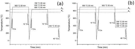 Figure 1. Heat treatments scheme: (a) the tests performed at different austenitizing and fixed austempering temperatures (route 1); (b) the tests performed at fixed austenitizing and different austempering temperatures (route 2).
 - Austempering (Route 2): pre-normalization treatment from 900 °C (30 min) and water-cooling. Heating at 900 °C for 30 min at 1 °C/s, air cooling at 10 °C/s to 300, 350 and 400 °C and holding for 30 min followed by water-cooling to room temperature at 40 °C/s (Figure 1b).
Microstructure evolution was investigated with a scanning electron microscope (SEM, Leica Cambridge Leo Stereoscan 440, Leica Microsystems S.r.l., Milan, Italy), operating with a secondary electron (SE) at 15 kV and in backscattered electron mode (BSE) at 25 kV. Heat-treated specimens were cut along the cross section with lubricated SiC disks, mounted using phenolic resin, ground with abrasive SiC papers (from 320 to 1200 grit) and polished using clothes and polycrystalline diamond suspensions of 6, 3 and 1 µm. In order to reveal microstructures, Nital 2 (2 mL of nitric acid in 98 mL of ethanol) etchant was used.
Phase identification and quantification were performed with X-ray diffraction, using a Siemens D500 X-ray diffractometer (Siemens, Munich, Germany), equipped with a monochromator on the detector side and a Cu radiation tube, working at 40 kV and 30 mA. The 2θ = 40–105° angular range was investigated with a step scan of 0.025° and a counting time of 6 s per step. The evaluation of the volume fraction of the phases was performed by means of Rietveld analysis with Maud software (Lutterotti, University of Trento, Department of Material Engineering, Trento, Italy).
The corrosion performances were investigated by potentiodynamic polarization tests (PDP) at room temperature. Polarization tests were performed in a borate buffer solution containing 0.3 M H3BO3 and 0.075 M Na2B4O7•10H2O (pH = 8.4) [31], using an AMEL 2549 Potentiostat (Amel Electrochemistry S.r.l., Milan, Italy). The reference electrode was a saturated calomel electrode (SCE), the counter electrode was a platinum electrode, and the scan rate was 0.5 mVs−1 in a potential range between OCP−0.2V (0.2 V below the measured OCP) and +2.5 V. The electrolyte was chosen in order to simulate a non-strongly aggressive environment to underline the effect of retained austenite in the material. Corrosion data (Ecorr and Icorr) were extrapolated graphically using the Tafel method.
EIS (electrochemical impedance spectroscopy) tests were also performed using the same cell and electrolyte of the PDP at the value of the open circuit potential, and in a range of frequency 105–10−2 Hz with a perturbation amplitude of 10 mV, after 30 min and 24 h of immersion. An AMEL 2549 Potentiostat (Amel Electrochemistry S.r.l.) coupled with a Materials Instrument Spectrometer was employed. The fitting of experimental data was carried out using the software ZView (Scribner Associates Inc, Southern Pines, NC, USA) and the Randles circuit as the equivalent circuit. Both PDP and EIS tests were performed after 30 min of OCP stabilization. Each measure was repeated three times in order to assure statistical reproducibility.
3. Results and Discussion
3.1. Microstructural Characterization
The microstructure of the samples was analyzed along the cross section by electron microscopy.
After normalization, as shown in Figure 2, the material exhibited a microstructure consisting of martensite and ferritic islands, located at the grain boundaries (allotriomorphic ferrite, FA) and in the center (idiomorphic ferrite, FI). The presence of martensite was due to the high amounts of alloying elements, which switched the transformation curves to higher times, decreasing the critical cooling rate necessary to avoid ferrite and pearlite formation. The trace of the prior austenite grain boundary is indicated by the dashed line in the figure.
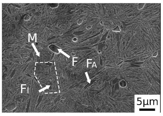
Figure 2.
SE-SEM image of material after normalization (M martensite, F ferrite, FA allotriomorphic ferrite and FI idiomorphic ferrite).
In Figure 3 are reported the SEM images after austempering performed at different austenitizing temperatures. In Figure 3a.1,a.2 it is possible to observe a dual-phase microstructure consisting of different ferrite morphologies and martensite. A similar microstructure was observed also by the authors in a previous research [23]. The austempering treatment in this condition does not lead to bainite formation. As state in ref. [23], this phenomenon could be explained by the carbon partitioning that changes Bs temperature, or due to the short soaking time at AT.
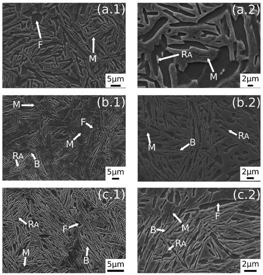
Figure 3.
SE-SEM images of the surfaces of the samples: (a.1,a.2) 780 °C + 350 °C, (b.1,b.2) 830 °C + 350 °C, (c.1,c.2) 850 °C + 350 °C. (M martensite, F ferrite, RA retained austenite, B carbide free bainite).
Figure 3b.1,b.2 shows the microstructure after austenitizing for 30 min at 830 °C. In this case the presence of carbide free bainite (B) can be noted. The microstructure consisted of a martensite matrix with ferritic islands and free-carbide bainite sheaves [16]. Increasing the austenitizing temperature to 850 °C (Figure 3c.1,c.2), the same microstructure is observed. The coarsening of bainitic sheaves should be observed when increasing the temperature from 830–850 °C, according to the literature [32], together with a decreasing width of martensitic regions. Figure 4 shows a high magnification image of the specimen treated at 850 °C for 30 min and austempered at 350 °C. It is possible to distinguish, as reported by numerous authors in the literature [15,16,33], two morphologies of retained austenite: (a) blocky type RA (RAB), with a low carbon concentration and a high tendency to exhibit a TRIP effect; (b) high-carbon film shape austenite (RAF) with high mechanical stability. Laths of martensite are also visible (M).
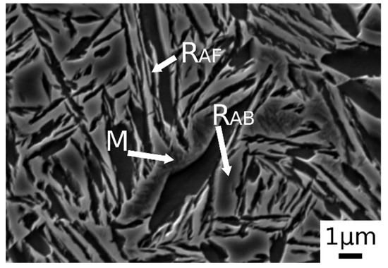
Figure 4.
SE-SEM image at high magnification of the alloy after austenitizing at 850 °C (30 min) and austempering at 350 °C for 30 min. (M martensite, RAB blocky retained austenite, RAF filmy retained austenite).
A further increase in austenitizing temperature (900 °C), maintaining 350 °C of austempering temperature, led to carbide-free bainitic sheaves coarsening, as can be noted in Figure 5b.1,b.2. The microstructure consisted of a martensitic matrix, as before, but with a higher amount of bainite.
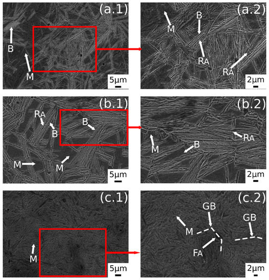
Figure 5.
SE-SEM images of the surfaces of the samples: (a.1,a.2) 900 °C + 300 °C, (b.1,b.2) 900 °C + 350 °C, (c.1,c.2) 900 °C + 400 °C. (M martensite, F ferrite, RA retained austenite, B carbide free bainite, GB prior austenite grain boundary, FA allotriomorphic ferrite).
A prevalent martensitic microstructure with free-carbide bainite sheaves randomly oriented was observed in the sample austenitized at 900 °C for 30 min and soaked at 300 °C for 30 min, as shown in Figure 5a.1,a.2. A lower amount of bainite was found with decreasing the AT temperature. This microstructural evolution could be related to the effect of AT on the kinetic of bainitic transformation. In fact, higher austempering temperatures fasten the bainitic transformation kinetics [4]. The observed microstructural evolution agreed with the literature [1,2,34,35].
Austempering at 400 °C produced a microstructure consisting of martensite (Figure 5c.1,c.2) without bainite, due to austempering at a temperature superior to Bs, as demonstrated in [23]. In the image are also indicated the trace of prior austenite grain boundaries (GB) with allotriomorphic ferrite (FA) [22]. RAB and RAF are recognizable also in the sample subjected to 900 °C austenitizing and 350 °C austempering (Figure 6). High-magnification micrographs allow for demonstrating that filmy austenite (RAF) is located between the bainitic laths, while the RAB are located at bainitic region boundaries.
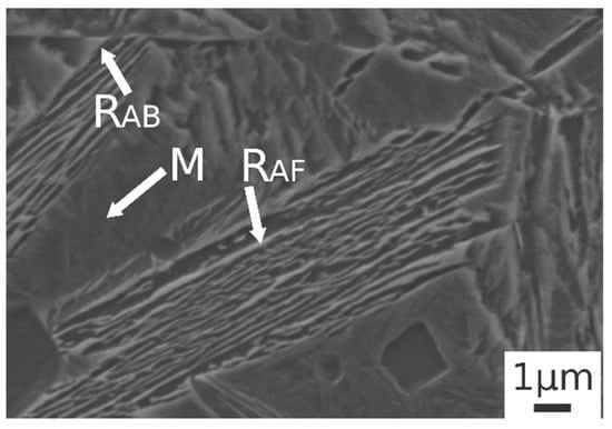
Figure 6.
SE-SEM image at high magnification of the alloy after austenitizing at 900 °C (30 min) and austempering at 350 °C for 30 min. (M martensite, RAB blocky retained austenite, RAF filmy retained austenite).
3.2. X-ray Diffraction
X-ray diffraction patterns of austenitized samples at 780 °C, 830 °C, 850 °C are shown in Figure 7. In all the patterns are visible BCC iron peaks related to ferrite and bainite, body-centered tetragonal iron peaks related to martensite, and FCC iron peaks related to the presence of retained austenite. Displacement between ferrite and martensite peaks should explained by the high martensite carbon content and strong cell distortion [23,36].
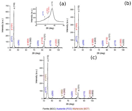
Figure 7.
XRD pattern (a) 780 °C + 350 °C, in the box upon on the right can be found a zoom of the pattern in the range 43–46°, (b) 830 °C + 350 °C, (c) 850 °C + 350 °C.
Figure 8 shows the XRD pattern of the sample austenitized at 900 °C and soaked at 300, 350 and 400 °C for 30 min.
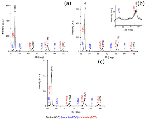
Figure 8.
XRD pattern (a) 900 °C + 300 °C, (b) 900 °C + 350 °C, in the box upon on the right can be found a zoom of the pattern in the range 88–102°, (c) 900 °C + 400 °C.
Table 3 reports the volume fraction of the phases calculated by means of the Rietveld analysis performed with the Maud software on the XRD patterns (Figure 7 and Figure 8). The results show that the microstructure mainly consisted of martensite and carbide free bainite with RA.
Table 3.
Results of phase quantification performed by Rietveld analysis.
By plotting the austenite volume fraction vs. the austenitizing temperature, it can be observed that (i) increasing the austenitizing temperature, from 780 °C to 850 °C, produced an increase in final Vγ, and that (ii) above 850 °C a decrease in the Vγ can be noted (Figure 9a).
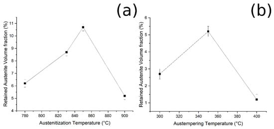
Figure 9.
Relationship between (a) RA and austenitizing temperature, and (b) RA and austempering temperature (fixed austenitizing at 900 °C).
Furthermore, when the material was austenitized at 900 °C, the volume fraction of retained austenite increased from 300 °C to 350 °C of austempering, and then decreased (Figure 9b). These results could be explained by considering the bainitic transformation process and the kinetics: the higher the carbide-free bainite volume fraction, the higher is the amount of RA stabilized and retained at room temperature. The obtained results agree with the literature [2,17,27].
3.3. Corrosion Resistance
The corrosion resistance of the specimens was preliminarily measured by PDP tests, in a borate buffer solution, and the PDP curves are reported in Figure 10a and Figure 11a. Values of corrosion potentials and current densities, graphically extrapolated from the curves, together with the corrosion rate, calculated with Equation (1), are reported in Table 4.
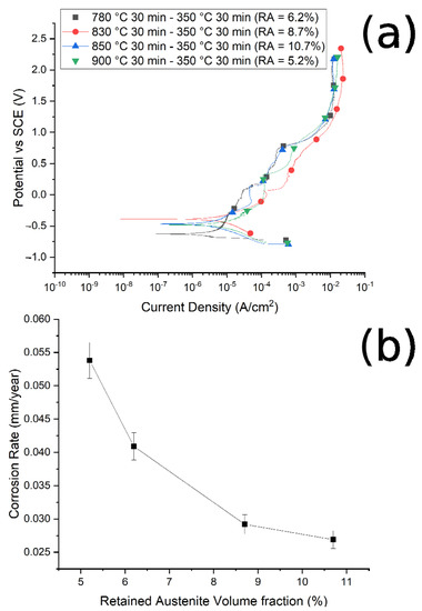
Figure 10.
(a) Potentiodynamic polarization curves for the different samples austenitized at 780 °C, 830 °C, 850 °C, 900 °C and austempered at 350 °C. (b) Correlation between corrosion rate and RA volume fraction. Test performed in borate buffer solution.
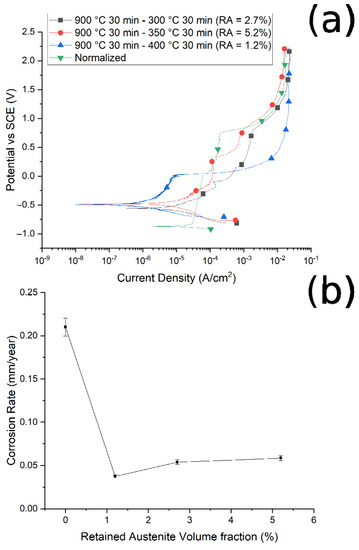
Figure 11.
(a) Polarization curves of the samples austenitized at 900 °C and austempered at 300 °C, 350 °C, and 400 °C, and normalized at 900 °C. (b) Relationship between corrosion rate and volume fraction of retained austenite. Test performed in borate buffer solution.
It is possible to note that, as the austenitizing temperature and volume fraction of the retained austenite increased, the Icorr decreased, the corrosion rate (CR) decreased and the corrosion resistance increased, in agreement with Han et al. [30]. In Figure 10b and Figure 11b are reported the trend of the corrosion rate (CT) with the RA volume fraction for the two studied routes. A clear correlation between the quantity of RA and the CR can be noted, especially in the case of route 1, with a decrease in the corrosion rate with the increase in the RA volume fraction. This phenomenon agrees with the results of Bignozzi et al. [27], who studied the effect of austenite on martensitic stainless steel’s resistance. The effect of RA was explained by Hill et al. [28,37]: austenite was characterized by a lower amount of internal stress with respect to martensite. According to the authors, higher stresses led to a corrosion rate increase.
The results were confirmed by Hsu et al. [38], who studied the corrosion behavior of ADI cast iron in a 3.5% NaCl environment. According to their results, retained austenite, produced by austempering, acts as a corrosion inhibitor, lowering the material degradation with high efficiency.
Moreover, the results were confirmed in the research conducted by Yang et al. [39]. The authors in ref. [38] analyzed the difference in corrosion resistance between the quenching and tempering treatment (Q&T) and the quenching and partitioning (Q&P) of a medium carbon steel, in a sodium chloride solution. The investigated alloy, after Q&P, was characterized by a high amount of RA (~17.5%) with respect to the sample treated by Q&T, and this exhibited better corrosion properties both in short- and long-time immersion.
It can be noted that, at fixed austenitizing temperatures (900 °C), when increasing the austempering temperature, specimens showed better corrosion resistance, in agreement with the literature [40]. For this austenitizing temperature, the variations in the corrosion properties are smaller than in the case of route 1, as can be observed when comparing Figure 11b with Figure 10b, due to the lower variation in RA content between the various samples.
Considering the corrosion potentials (Ecorr), an ennoblement in the corrosion potential can be observed for all the treated samples in comparison to the normalized sample (with no RA), confirming the increased corrosion performances of the samples that contained RA. In fact, an increase in the corrosion potential indicates and ennoblement of the tested material, and so an increase in the corrosion properties.
From the observation of the surface of the corroded samples (in Figure 12 is presented an example, but all the samples present the same surface after corrosion), it was possible to recognize mainly a uniform corrosion, with some localized corrosion sites, in accordance with the employed electrolyte. This allowed the application of the formula for corrosion rate (1) calculation reported in ASTM G102 [41],
where:
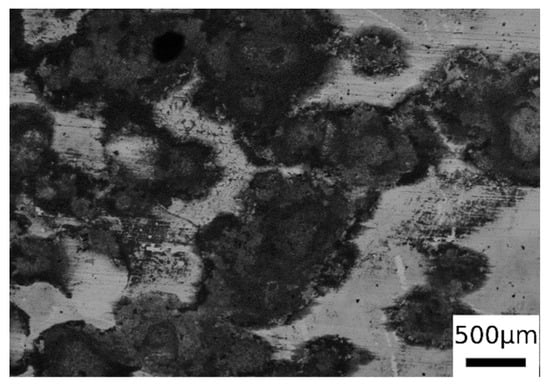
Figure 12.
SEM micrographs surface of one sample after PDP tests (BSE mode) for the sample austenitized at 900 °C (30 min) and austempering at 350 °C for 30 min.
- (a)
- CR is the corrosion rate (mm/year);
- (b)
- Ki is a constant equal to 3.27 × 10⁻³;
- (c)
- Icorr is the current density (µA/cm2);
- (d)
- ρ is the material density, assumed equal to 7.8 g/cm3;
- (e)
- EW is the so-called equivalent weight, calculated according to (2),
Further investigation on the corrosion behavior was performed with EIS tests on the samples with the best and the worst corrosion resistance, after 30 min and 24 h immersion in borate buffer solution.
The results, in term of Nyquist, Bode Modulus and Phase diagrams, are reported in Figure 13.
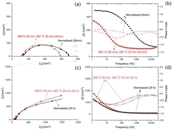
Figure 13.
(a) Nyquist plot for the material austempered at 350 °C after austenitizing at 850 °C and in normalized conditions for 30 min immersion. (b) Bode modulus and phase plot for or the material austempered at 350 °C after austenitizing at 850 °C and in the normalized condition for 30 min immersion. (c) Nyquist plot for the material austempered at 350 °C after austenitizing at 850 °C, and in normalized condition for 24 h immersion. (d) Bode and phase plots for the material austempered at 350 °C after austenitizing at 850 °C and in normalized condition for 24 h immersion. All the tests were performed in borate buffer solution. Dots represent experimental data, lines the results of the fitting.
The obtained EIS data were fitted using the equivalent circuit shown in Figure 14, called Randles circuit, and the results are reported in Table 5. In this circuit, RS represents the resistance of the electrolyte, R0 is the polarization resistance, which depends on the passive oxide film and is a measure of the corrosion resistance of the material, and CPEO is a constant phase element, used instead of a capacitance because the measured capacitance is not ideal. The choice of the equivalent circuit is in accordance with the shape of the Bode plots, which showed a single time constant, and with the literature regarding natural oxide films on steels [42].
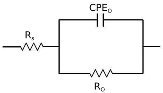
Figure 14.
Equivalent circuit used for the fitting of EIS data.
Table 5.
Results of the fitting of the experimental data with the equivalent circuit of Figure 14 for the material austempered at 350 °C after austenitizing at 850 °C and in normalized condition.
The quality of the fitting of EIS data after both 30 min and 24 h of immersion was good, as confirmed by the low values of chi squared.
From the Nyquist plots a qualitative evaluation of the polarization resistance can be performed considering this as the real part of the impedance at low frequencies (or from the Bode modulus plot as the interception with the Y axis). This value of polarization resistance is a measure of the protective properties of the oxide coating formed on the steel.
After 30 min of immersion in the solution, no significant differences in terms of ZR at low frequencies, and so in the polarization resistance, could be observed. This indicated that the different corrosion performance recorded in the PDP tests was not related to the characteristics of a passive layer (measured by EIS tests), but to the amount of retained austenite in the samples. In fact, RA, given its low amount of internal defects, reduces the amount of residual stress in the material, making it less susceptible to corrosion. This agreed with the results in the literature [26,27,28].
The data in Table 5 confirmed the results of the qualitative evaluation from the diagrams, in fact the values of Ro, that is the polarization resistance given by the oxide layer, are similar between the two samples. This allowed us to state that after 30 min of immersion, the volume fraction of RA did not influence the protective properties of the oxide film.
Similarly, after 24 h of immersion, no significant differences between the two specimens are observable in term of polarization resistance, Ro, both from the qualitative evaluation of the diagrams and from the analysis of the data in Table 5. Moreover, it is possible to observe that a long immersion period led to an increase in terms of Ro, due to the formation of a thicker passive layer, with semi conductive properties, as demonstrated by Hamadou [43] and Oblonsky [44]. The application of surface-enhanced Raman spectroscopy (SERS) on passive films in borate buffer solutions allowed Oblonsky, in ref. [44], to determine its composition: a mixture of amorphous Fe(OH)2, γ-Fe2O3 and Fe3O4. It is permissible to think that a passive oxide film with a similar composition is formed on the surface of the steel examined in this work.
4. Conclusions
In this work a novel composition of high silicon steel has been studied. It was observed that:
- Austenitizing at 780 °C and austempering at 350 °C produced a dual-phase, ferritic-martensitic microstructure. By increasing the austempering temperature carbide-free bainite was formed, and, as the temperature increased, a coarsening of the bainitic sheaves was observed;
- Increasing the austenitizing temperature from 780 to 850 °C led to an increase in the retained austenite volume fraction, thanks to the increase in bainite amount, which favors carbon partitioning;
- At fixed austenitizing condition (900 °C), the bainite and RA amount increased with the austempering temperature up to 350 °C, whereas at 400 °C no bainite was found due to the absence of bainitic transformation, because 400 °C is above Bs;
- The corrosion resistance of the samples increased with the volume fraction of retained austenite;
- The variation in the corrosion properties, at 30 min of immersion in borate buffer solution, was not linked with variations in the protective properties of the oxide layer (Which did not change from EIS tests), but with the lower amount of residual stresses in the samples with higher amounts of retained austenite;
- The EIS tests, after 24 h of immersion in borate buffer solution, showed that the differences in the RA volume fraction did not produce differences in term of the polarization resistance of the oxide layer even after immersion. The polarization resistance, Ro, of the sample immersed for 24 h was higher than that of the sample after 30 min of immersion, due to the growth of a thicker passive film.
Author Contributions
Conceptualization, M.D., M.P. (Marina Polyakova) and K.B.; methodology, C.G. and L.P.; software, D.K. and M.F.; validation, D.K. and C.G.; formal analysis, M.F. and D.K.; investigation, A.G.S., M.F., M.P. (Mirko Pigato), L.P. and C.G.; resources, M.D., K.B. and M.P. (Marina Polyakova); data curation, M.F., A.G.S. and C.G.; writing—original draft preparation, M.F., L.P. and C.G.; writing—review and editing, L.P. and C.G.; visualization, M.F. and C.G.; supervision, K.B., M.P. (Marina Polyakova) and M.D.; project administration, M.D. and M.P. (Marina Polyakova); funding acquisition, M.D. and M.P. (Marina Polyakova). All authors have read and agreed to the published version of the manuscript.
Funding
The authors want to thank FONDAZIONE CARIPARO for the financial support with the visiting program TIP-STEP.
Institutional Review Board Statement
Not applicable.
Informed Consent Statement
Not applicable.
Data Availability Statement
The raw/processed data required to reproduce these findings cannot be shared at this time as the data also forms part of an ongoing study.
Conflicts of Interest
The authors declare no conflict of interest.
References
- Putatunda, S.K.; Singar, A.V.; Tackett, R.; Lawes, G. Development of a high strength high toughness ausferritic steel. Mater. Sci. Eng. A 2009, 513–514, 329–339. [Google Scholar] [CrossRef]
- Putatunda, S.K. Fracture toughness of a high carbon and high silicon steel. Mater. Sci. Eng. A 2001, 297, 31–43. [Google Scholar] [CrossRef]
- Changlea, Z.; Shouhai, L.; Hanguanga, F.; Yinghua, L. Microstructure evolution and wear resistance of high silicon bainitic steel after austempering. J. Mater. Res. Technol. 2020, 9, 4826–4839. [Google Scholar] [CrossRef]
- Fonstein, N. Advanced High Strength Sheet Steels: Physical Metallurgy, Design, Processing, and Properties; Springer: Cham, Switzerland, 2015; ISBN 9783319191652. [Google Scholar]
- Qian, L.; Zhou, Q.; Zhang, F.; Meng, J.; Zhang, M.; Tian, Y. Microstructure and mechanical properties of a low carbon carbide-free bainitic steel co-alloyed with Al and Si. Mater. Des. 2012, 39, 264–268. [Google Scholar] [CrossRef]
- Zhu, L.J.; Wu, D.; Zhao, X.M. Effect of silicon addition on recrystallization and phase transformation behavior of high-strength hot-rolled trip steel. Acta Metall. Sin. Engl. Lett. 2008, 21, 163–168. [Google Scholar] [CrossRef]
- de Oliveira, P.G.B.; Mariani, F.E.; Casteletti, L.C.; Itman Filho, A.; Neto, A.L.; Totten, G.E. Boro-Austempering Treatment of High-Strength Bainitic Steels. J. Mater. Eng. Perform. 2020, 29, 3486–3493. [Google Scholar] [CrossRef]
- Bahadur, S.; State, I.; Verhoeven, J.D.; State, I. Friction and wear behavior of high silicon bainitic structures in austempered cast iron and steel. Wear 1990, 138, 269–284. [Google Scholar]
- Pezzato, L.; Gennari, C.; Chukin, D.; Toldo, M.; Sella, F.; Toniolo, M.; Zambon, A.; Brunelli, K.; Dabalà, M. Study of the effect of multiple tempering on the impact toughness of forged s690 structural steel. Metals 2020, 10, 507. [Google Scholar] [CrossRef]
- Konstantinov, D.V.; Bzowski, K.; Korchunov, A.G.; Kuziak, R.; Pietrzyk, M.; Shiryaev, O.P. Multiscale Modelling of Structural and Phase Transformations in Steel During Drawing. Vestn. Nosov Magnitogorsk State Tech. Univ. 2016, 14, 90–98. [Google Scholar] [CrossRef]
- Konstantinov, D.V.; Korchunov, A.G. Multi-Scale Computer Simulation of Metal Forming Processes. Vestn. Nosov Magnitogorsk State Tech. Univ. 2015, 1, 36–43. [Google Scholar]
- Sherif, M.Y.; Mateo, C.G.; Sourmail, T.; Bhadeshia, H.K.D.H. Stability of retained austenite in TRIP-assisted steels. Mater. Sci. Technol. 2004, 20, 319–322. [Google Scholar] [CrossRef]
- Pereloma, E.V.; Gazder, A.A.; Timokhina, I.B. Addressing retained austenite stability in advanced high strength steels. In Proceedings of the Materials Science Forum, Saint-Petersburg, Russia, 9−16 September 2013; Volume 738–739, pp. 212–216. [Google Scholar]
- Podder, A.S.; Lonardelli, I.; Molinari, A.; Bhadeshia, H.K.D.H. Thermal stability of retained austenite in bainitic steel: An in situ study. R. Soc. A Math. Phys. Eng. Sci. 2011, 467, 3141–3156. [Google Scholar] [CrossRef]
- Efremenko, V.G.; Hesse, O.; Friedrich, T.; Kunert, M.; Brykov, M.N.; Shimizu, K.; Zurnadzhy, V.I.; Šuchmann, P. Two-body abrasion resistance of high-carbon high-silicon steel: Metastable austenite vs nanostructured bainite. Wear 2019, 418–419, 24–35. [Google Scholar] [CrossRef]
- Zhao, J.; Lv, B.; Zhang, F.; Yang, Z.; Qian, L.; Chen, C.; Long, X. Effects of austempering temperature on bainitic microstructure and mechanical properties of a high-C high-Si steel. Mater. Sci. Eng. A 2019, 742, 179–189. [Google Scholar] [CrossRef]
- Changle, Z.; Hanguang, F.; Shengqiang, M.; Jian, L.; Yongping, L. Microstructure and properties of high-Si high-Mn bainitic steel after heat treatment. Mater. Res. Express 2019, 6. [Google Scholar] [CrossRef]
- Palaksha, P.A.; Ravishankar, K.S. Influence of Austempering Heat Treatment on Microstructure and Mechanical Properties of Medium Carbon High Silicon Steel. IOP Conf. Ser. Mater. Sci. Eng. 2017, 225. [Google Scholar] [CrossRef]
- Son, J.Y.; Kim, J.H.; Kim, W.B.; Ye, B.J. Effects of austempering conditions on the microstructures and mechanical properties in Fe-0.9%C-2.3%Si-0.3%Mn steel. Met. Mater. Int. 2010, 16, 357–361. [Google Scholar] [CrossRef]
- Kumar, R.; Dwivedi, R.K.; Ahmed, S. Stability of Retained Austenite in Carbide Free Bainite during the Austempering Temperature and its Influence on Sliding Wear of High Silicon Steel. Silicon 2020. [Google Scholar] [CrossRef]
- Acharya, P.P.; Udupa, R.; Bhat, R. Microstructure and mechanical properties of austempered AISI 9255 high-silicon steel. Mater. Sci. Technol. 2018, 34, 355–365. [Google Scholar] [CrossRef]
- Zhao, J.; Li, J.; Ji, H.; Wang, T. Effect of austenitising temperature on mechanical properties of nanostructured bainitic steel. Materials 2017, 10, 874. [Google Scholar] [CrossRef] [PubMed]
- Franceschi, M.; Pezzato, L.; Gennari, C.; Fabrizi, A.; Polyakova, M.; Konstantinov, D.; Brunelli, K.; Dabalà, M. Effect of intercritical annealing and austempering on the microstructure and mechanical properties of a high silicon manganese steel. Metals 2020, 10, 1448. [Google Scholar] [CrossRef]
- Lucio-Garcia, M.A.; Gonzalez-Rodriguez, J.G.; Casales, M.; Martinez, L.; Chacon-Nava, J.G.; Neri-Flores, M.A.; Martinez-Villafañe, A. Effect of heat treatment on H2S corrosion of a micro-alloyed C-Mn steel. Corros. Sci. 2009, 51, 2380–2386. [Google Scholar] [CrossRef]
- Isfahany, A.N.; Saghafian, H.; Borhani, G. The effect of heat treatment on mechanical properties and corrosion behavior of AISI420 martensitic stainless steel. J. Alloys Compd. 2011, 509, 3931–3936. [Google Scholar] [CrossRef]
- Pezzato, L.; Lago, M.; Brunelli, K.; Breda, M.; Calliari, I. Effect of the Heat Treatment on the Corrosion Resistance of Duplex Stainless Steels. J. Mater. Eng. Perform. 2018, 27, 3859–3868. [Google Scholar] [CrossRef]
- Bignozzi, M.C.; Calcinelli, L.; Carati, M.; Ceschini, L.; Chiavari, C.; Masi, G.; Morri, A. Effect of Heat Treatment Conditions on Retained Austenite and Corrosion Resistance of the X190CrVMo20-4-1 Stainless Steel. Met. Mater. Int. 2019, 26, 1318–1328. [Google Scholar] [CrossRef]
- Hill, H.; Raab, U.; Weber, S.; Theisen, W.; Wollmann, M.; Wagner, L. Influence of heat treatment on the performance characteristics of a plastic mold steel. Steel Res. Int. 2011, 82, 1290–1296. [Google Scholar] [CrossRef]
- Candelária, A.F.; Pinedo, C.E. Influence of the heat treatment on the corrosion resistance of the martensitic stainless steel type AISI 420. J. Mater. Sci. Lett. 2003, 22, 1151–1153. [Google Scholar] [CrossRef]
- Han, C.F.; Wang, Q.Q.; Sun, Y.F.; Li, J. Effects of Molybdenum on the Wear Resistance and Corrosion Resistance of Carbidic Austempered Ductile Iron. Metallogr. Microstruct. Anal. 2015, 4, 298–304. [Google Scholar] [CrossRef]
- Modiano, S.; Fugivara, C.S.; Benedetti, A.V. Effect of citrate ions on the electrochemical behaviour of low-carbon steel in borate buffer solutions. Corros. Sci. 2004, 46, 529–545. [Google Scholar] [CrossRef]
- Yuan, L.; Liu, Q.; Li, H.; Gao, B. Effect of Austenitizing Temperature on the Bainitic Transformation in a High-Carbon High-Silicon Steel. Met. Sci. Heat Treat. 2015, 57, 156–160. [Google Scholar] [CrossRef]
- Podder, A.S.; Bhadeshia, H.K.D.H. Thermal Stability of Austenite Retained in Bainitic Steels. Mater. Sci. Eng. A 2010, 527, 2121–2128. [Google Scholar] [CrossRef]
- Putatunda, S.K. Influence of austempering temperature on microstructure and fracture toughness of a high-carbon, high-silicon and high-manganese cast steel. Mater. Des. 2003, 24, 435–443. [Google Scholar] [CrossRef]
- Moghaddam, P.V.; Hardell, J.; Vuorinen, E.; Prakash, B. Effect of retained austenite on adhesion-dominated wear of nanostructured carbide-free bainitic steel. Tribol. Int. 2020, 150, 106348. [Google Scholar] [CrossRef]
- Luo, Q. A new XRD method to quantify plate and lath martensites of hardened medium-carbon steel. J. Mater. Eng. Perform. 2016, 25, 2170–2179. [Google Scholar] [CrossRef]
- Hill, H.; Huth, S.; Weber, S.; Theisen, W. Corrosion properties of a plastic mould steel with special focus on the processing route. Mater. Corros. 2011, 62, 436–443. [Google Scholar] [CrossRef]
- Hsu, C.H.; Chen, M.L. Corrosion behavior of nickel alloyed and austempered ductile irons in 3.5% sodium chloride. Corros. Sci. 2010, 52, 2945–2949. [Google Scholar] [CrossRef]
- Yang, J.; Lu, Y.; Guo, Z.; Gu, J.; Gu, C. Corrosion behaviour of a quenched and partitioned medium carbon steel in 3.5 wt.% NaCl solution. Corros. Sci. 2018, 130, 64–75. [Google Scholar] [CrossRef]
- Aithal, P.M.; Vijayan, V.; Surendranathan, A.O.; Udupa, K.R.; Samuel, K.G. Corrosion behavior of high and low temperature austempered ductile iron (ADI) in iron ore slurry. Mater. Perform. Charact. 2017, 6, 369–378. [Google Scholar] [CrossRef]
- ASTM G102 Standard Practice for from Electrochemical Measurements. Astm 2015, 89, 1–7. [CrossRef]
- Pezzato, L.; Brunelli, K.; Dolcet, P.; Dabalà, M. Plasma electrolytic oxidation coating produced on 39NiCrMo3 steel. Surf. Coat. Technol. 2016, 307, 73–80. [Google Scholar] [CrossRef]
- Hamadou, L.; Kadri, A.; Benbrahim, N. Characterisation of passive films formed on low carbon steel in borate buffer solution (pH 9.2) by electrochemical impedance spectroscopy. Appl. Surf. Sci. 2005, 252, 1510–1519. [Google Scholar] [CrossRef]
- Oblonsky, L.J. A surfave enhanced Raman spectroscopic study of the passive films formed in borate buffer of iron, nickel, chromium and stainless steel. Science 1995, 37, 17–41. [Google Scholar]


Publisher’s Note: MDPI stays neutral with regard to jurisdictional claims in published maps and institutional affiliations. |
© 2021 by the authors. Licensee MDPI, Basel, Switzerland. This article is an open access article distributed under the terms and conditions of the Creative Commons Attribution (CC BY) license (http://creativecommons.org/licenses/by/4.0/).