Impact of Plasma Pre-Treatment on the Tribological Properties of DLC Coatings on PDMS Substrates


Abstract
:1. Introduction
2. Materials and Methods
2.1. PDMS Substrate Preparation
2.2. Plasma Modification of PDMS Substrates
2.3. Characterisation Methods
3. Results and Discussion
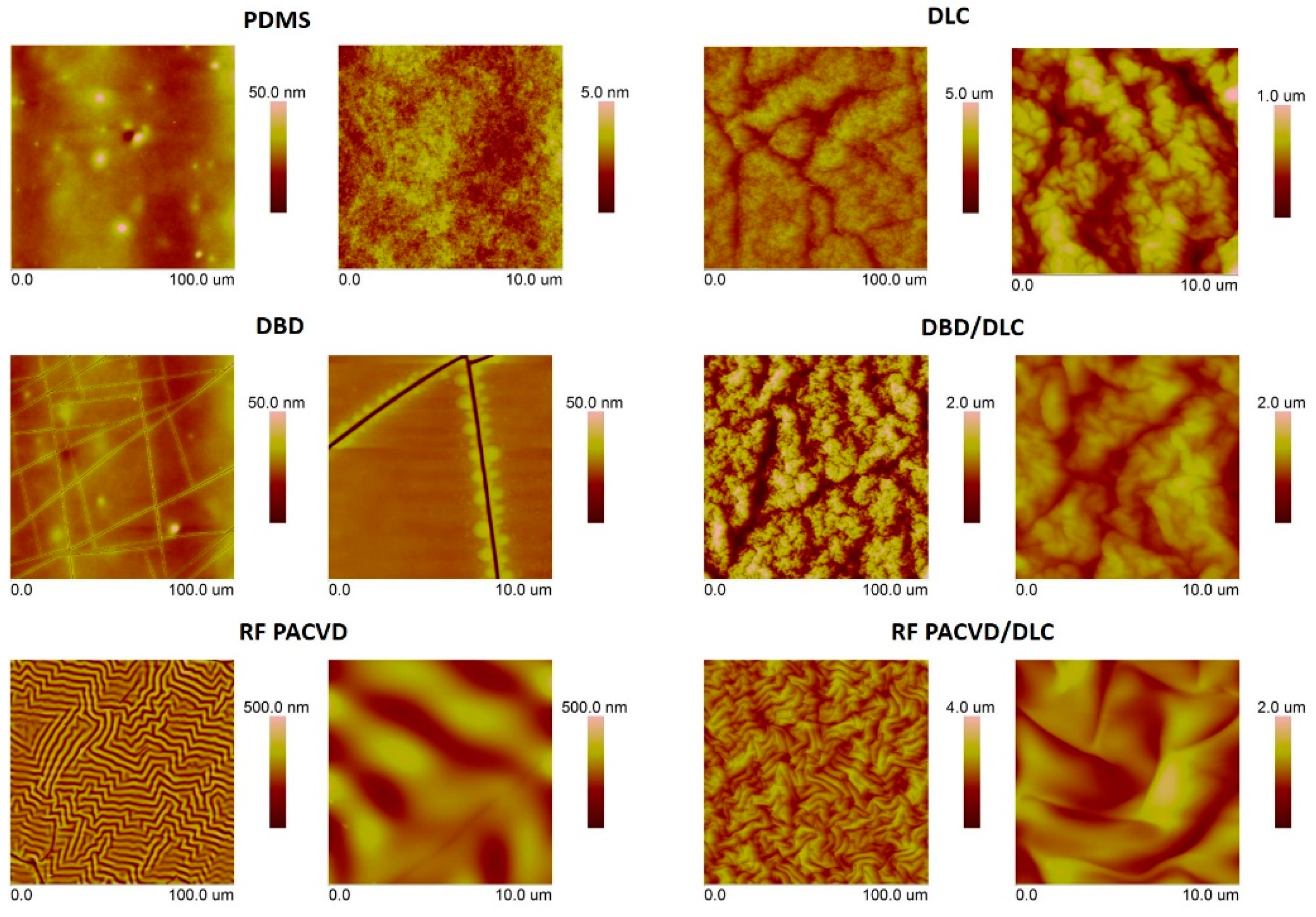
3.1. Surface Geometrical Structure
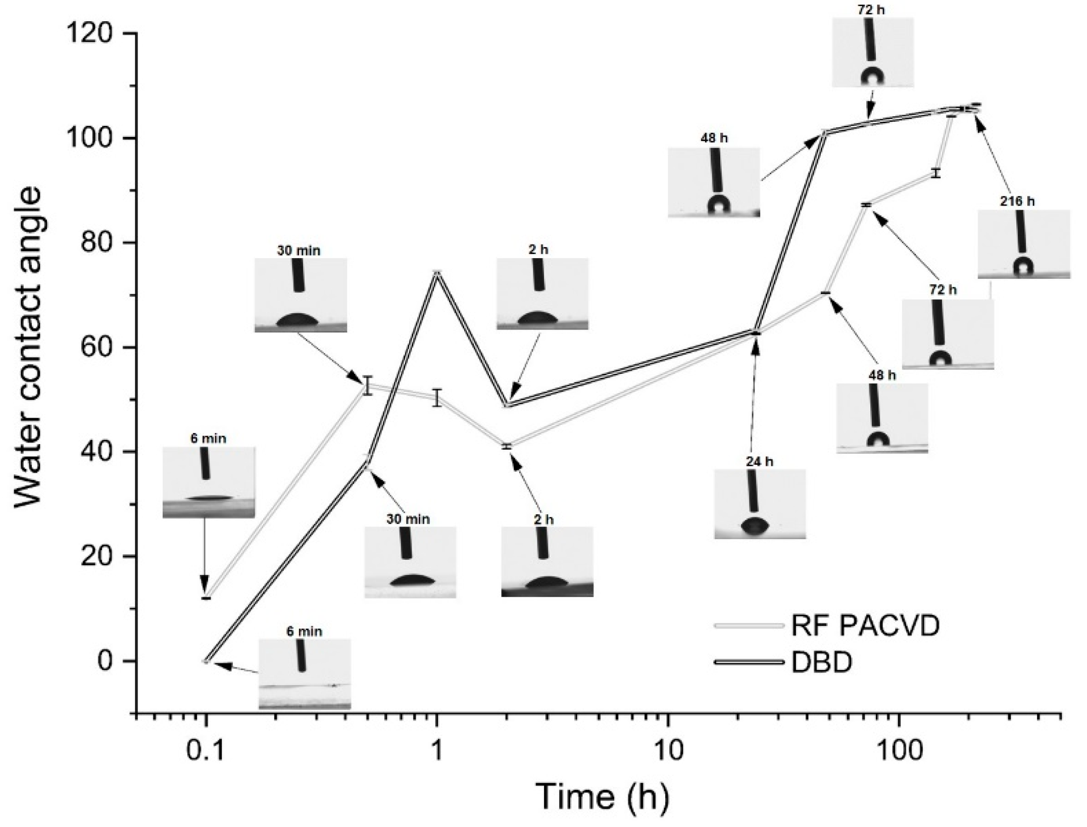
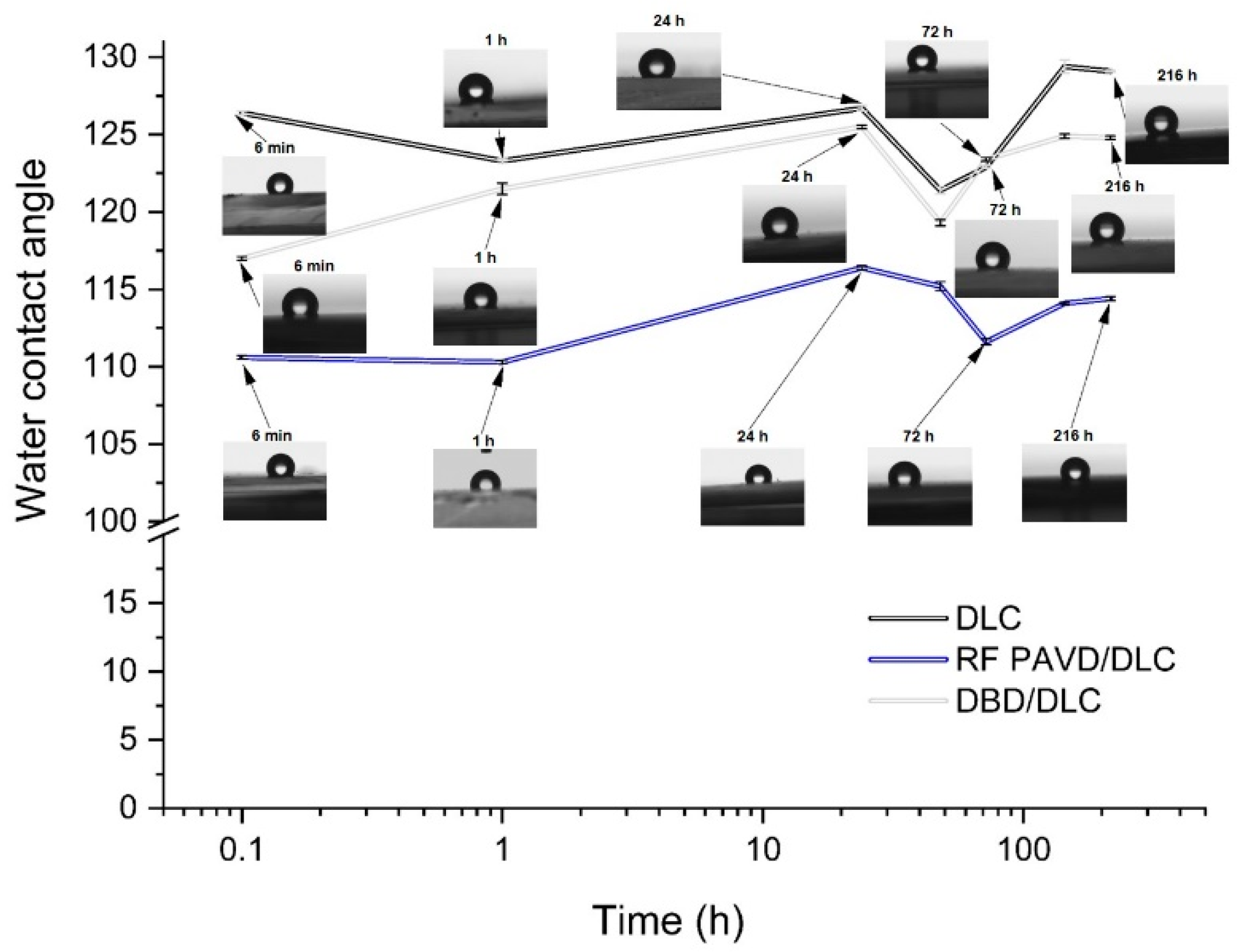
3.2. Changes in the Water Contact Angle before and after the Production of DLC Coatings
3.3. Chemical Structure Analysis
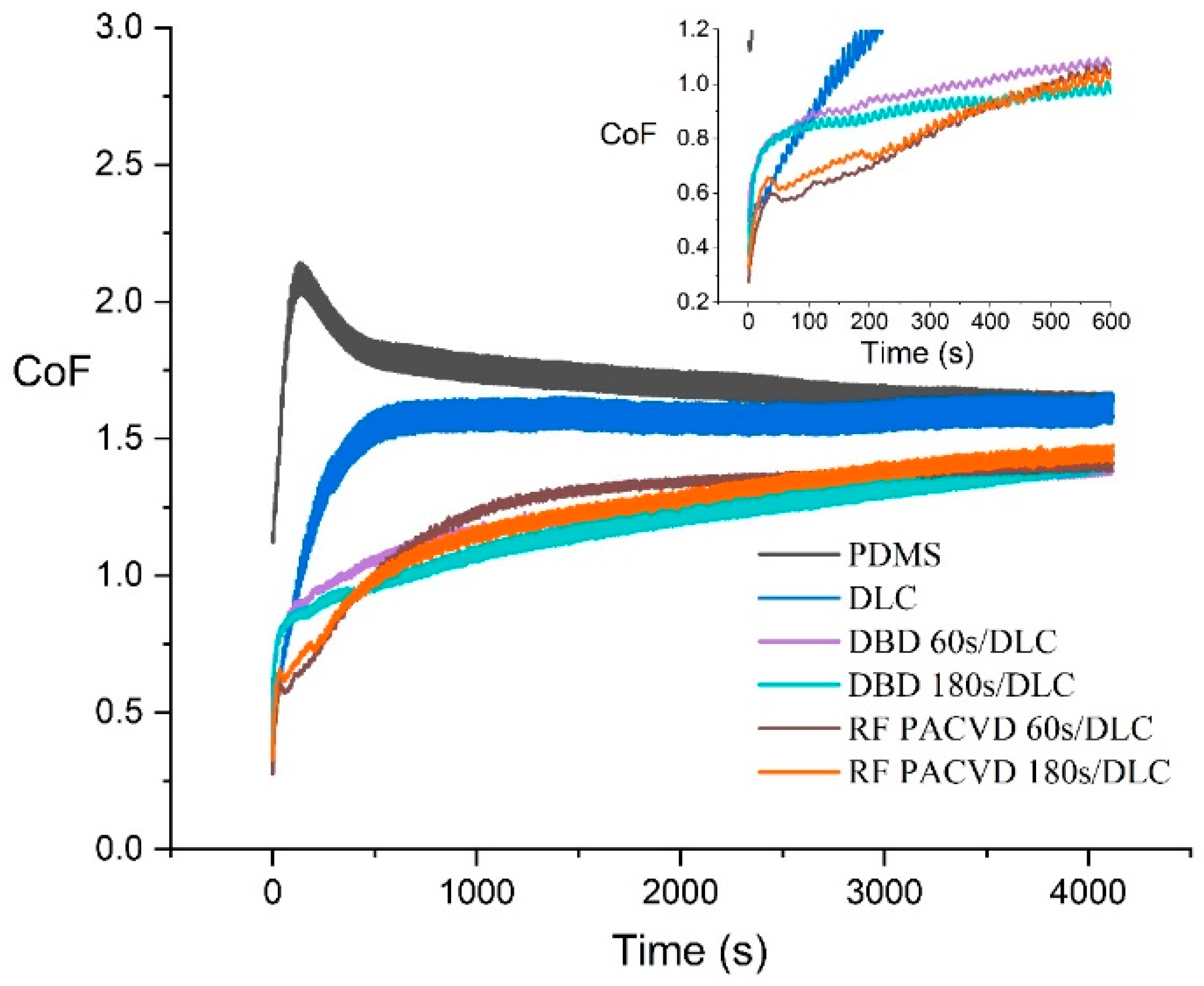
3.4. Analysis of the Coefficient of Friction
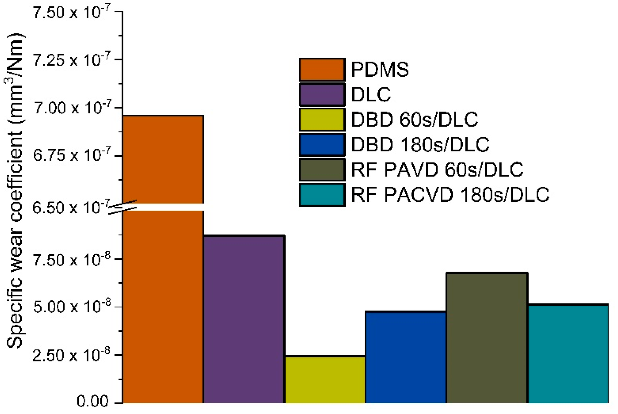
3.5. Wear Rate
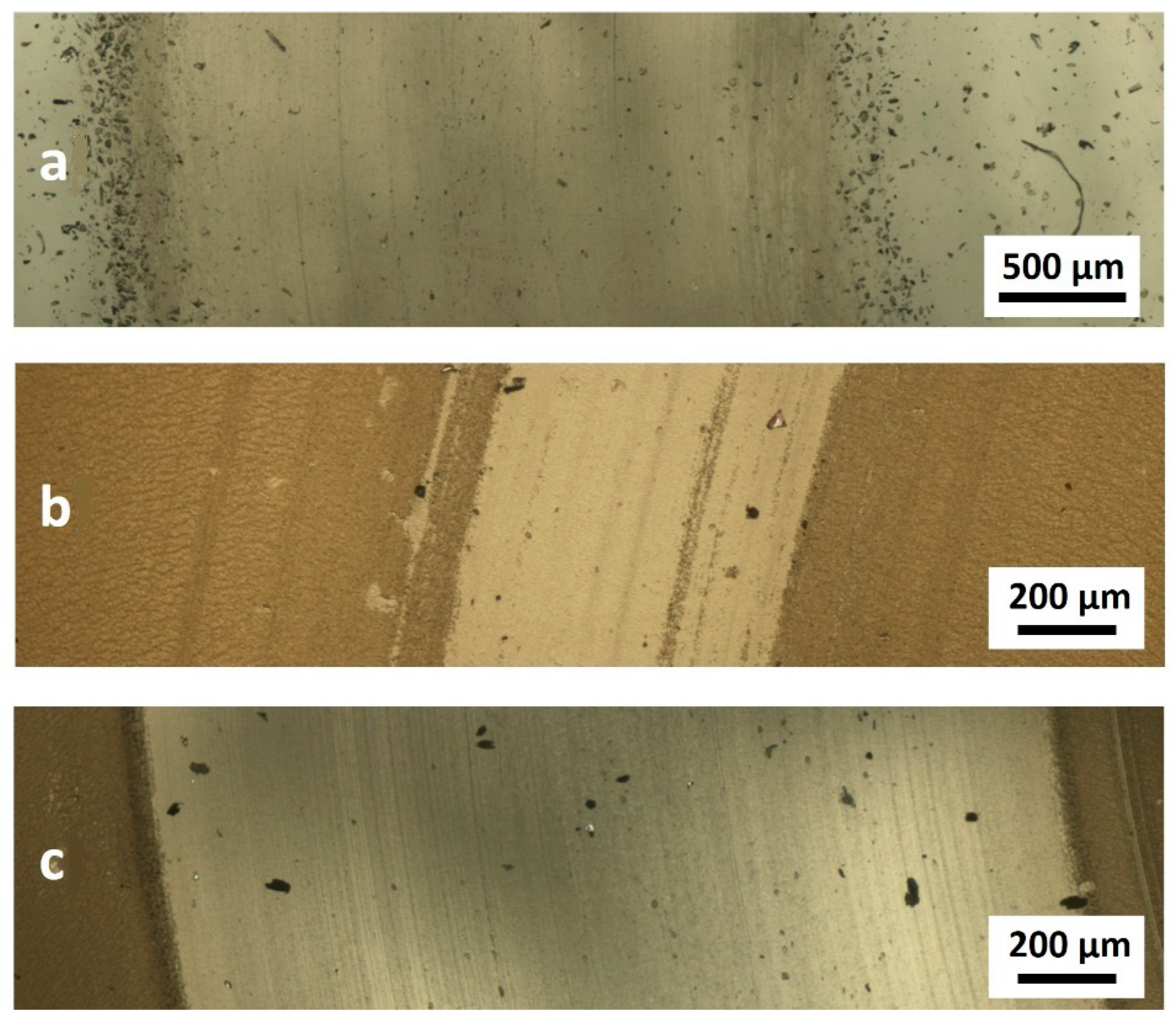
3.6. Wear Analysis
4. Discussion
5. Conclusions
Author Contributions
Funding
Institutional Review Board Statement
Informed Consent Statement
Data Availability Statement
Acknowledgments
Conflicts of Interest
References
- Kasiorowski, T.; Lin, J.; Soares, P.; Lepienski, C.M.; Neitzke, C.A.; De Souza, G.B.; Torres, R.D. Microstructural and tribological characterization of DLC coatings deposited by plasma enhanced techniques on steel substrates. Surf. Coat. Technol. 2020, 389, 125615. [Google Scholar] [CrossRef]
- Fiaschi, G.; Rota, A.; Ballestrazzi, A.; Marchetto, D.; Vezzalini, E.; Valeri, S. A chemical, mechanical, and tribological analysis of DLC coatings deposited by magnetron sputtering. Lubricants 2019, 7, 38. [Google Scholar] [CrossRef] [Green Version]
- Kaczorowski, W.; Batory, B.; Szymański, W.; Niedzielski, P. Evaluation of the surface properties of PEEK substrate after two-step plasma modification: Etching and deposition of DLC coatings. Surf. Coat. Technol. 2015, 333, 92–98. [Google Scholar] [CrossRef]
- Li, C.; Huang, L.; Yuan, J. Effect of sp3 content on adhesion and tribological properties of non-hydrogenated DLC films. Materials 2020, 13, 1911. [Google Scholar] [CrossRef] [Green Version]
- Grabarczyk, J.; Gaj, J.; Pazik, B.; Kaczorowski, W.; Januszewicz, B. Tribocorrosion behavior of Ti6Al4V alloy after thermo-chemical treatment and DLC deposition for biomedical applications. Tribol. Int. 2020, 153, 106560. [Google Scholar] [CrossRef]
- Liao, T.T.; Zhang, T.F.; Li, S.S.; Deng, Q.Y.; Wu, B.J.; Zhang, Y.Z.; Zhou, Y.J.; Guo, Y.G.; Leng, Y.X.; Huang, N. Biological responses of diamond-like carbon (DLC) films with different structures in biomedical application. Mat. Sci. Eng. C 2016, 69, 751–759. [Google Scholar] [CrossRef]
- Kaczorowski, W.; Batory, D.; Jakubowski, W.; Szymański, W.; Komorowski, P.; Walkowiak, B.; Sanak, M.; Niedzielski, P. Physicochemical and Biological Investigation of Different Structures of Carbon Coatings Deposited onto Polyurethane. Braz. Arch. Biol. Technol. 2016, 59, e16150305. [Google Scholar] [CrossRef] [Green Version]
- Marciano, F.R.; Bonetti, L.F.; Da-Silva, N.S.; Corat, E.J.; Trava-Airoldi, V.J. Diamond-like carbon films produced from high deposition rates exhibit antibacterial activity. Synth. Met. 2009, 159, 2167–2169. [Google Scholar] [CrossRef]
- Dearnaley, G.; Arps, J.H. Biomedical applications of diamond-like carbon (DLC) coatings: A review. Surf. Coat. Technol. 2005, 200, 2518–2524. [Google Scholar] [CrossRef]
- Kumar, C.; Majumder, H.; Khan, A.; Kumar Patel, S. Applicability of DLC and WC/C low friction coatings on Al2O3/TiCN mixed ceramic cutting tools for dry machining of hardened 52100 steel. Ceram. Int. 2020, 46, 11889–11897. [Google Scholar] [CrossRef]
- Huang, L.; Yuan, J.; Li, C.; Hong, D. Microstructure, tribological and cutting performance of Ti-DLC/α-C:H multilayer film on cemented carbide. Surf. Coat. Technol. 2018, 353, 163–170. [Google Scholar] [CrossRef]
- Alotaibi, S.; Manjunatha, K.M.; Paul, S. Stability of hydrogenated amorphous carbon thin films for application in electronic devices. Diam. Relat. Mater. 2018, 90, 172–180. [Google Scholar] [CrossRef]
- Agnello, S.; Messina, F. Optical and Electronic Properties of Carbon-Based Nanomaterials and Composites. J. Carbon Res. 2020, 6, 36. [Google Scholar] [CrossRef]
- Liu, C.-W.; Chen, W.-E.; Sun, Y.T.A.; Lin, C.-R. Fabrication and electrochemistry characteristics of nickel-doped diamond-like carbon film toward applications in non-enzymatic glucose detection. Appl. Surf. Sci. 2018, 436, 967–973. [Google Scholar] [CrossRef]
- Son, M.J.; Zhang, T.F.; Jo, Y.J.; Kim, K.H. Enhanced electrochemical properties of the DLC films with an arc interlayer, nitrogen doping and annealing. Surf. Coat. Technol. 2017, 329, 77–85. [Google Scholar] [CrossRef]
- Kaczorowski, W.; Gajewski, K.; Szymanski, W.; Batory, D.; Wojciechowska, A.; Swiatek, L.; Gotszalk, T.; Niedzielski, P. Evaluation of mechanical properties of carbon coatings synthesised in radio frequency plasma on PDMS. Surf. Coat. Technol. 2018, 333, 220–228. [Google Scholar] [CrossRef]
- Kaczorowski, W.; Batory, B.; Szymański, W.; Kaźmierczak, T.; Kotela, I.; Niedzielski, P. Frictional behavior of polyurethane modified by carbon coatings synthesized in dual-frequency plasma. Tribol. Trans. 2016, 59, 530–537. [Google Scholar] [CrossRef]
- Calzado-Martín, A.; Saldaña, L.; Korhonen, H.; Soininen, A.; Kinnari, T.J.; Gómez-Barrena, E.; Tiainen, V.-M.; Lappalainen, R.; Munuera, L.; Konttinen, Y.T.; et al. Interactions of human bone cells with diamond-like carbon polymer hybrid coatings. Acta Biomater. 2010, 6, 3325–3338. [Google Scholar] [CrossRef]
- Bai, C.; Liang, A.; Cao, Z.; Qiang, L.; Zhang, J. Achieving a high adhesion and excellent wear resistance diamond-like carbon film coated on NBR rubber by Ar plasma pretreatment. Diam. Relat. Mater. 2018, 89, 84–93. [Google Scholar] [CrossRef]
- Rahmawan, Y.; Moon, M.W.; Kim, K.S.; Lee, K.R.; Suh, K.Y. Wrinkled, Dual-Scale Structures of Diamond-Like Carbon (DLC) for Superhydrophobicity. Langmuir 2010, 26, 484–491. [Google Scholar] [CrossRef]
- Kim, S.J.; Yoon, J.I.; Moon, M.W.; Lee, K.R. Frictional behavior on wrinkle patterns of diamond-like carbon films on soft polymer. Diam. Relat. Mater. 2012, 23, 61–65. [Google Scholar] [CrossRef]
- Ban, M.; Tobe, S.; Takeuchi, L. Effects of diamond-like carbon thin film and wrinkle microstructure on cell proliferation. Diam. Relat. Mater. 2018, 90, 194–201. [Google Scholar] [CrossRef]
- Sung, T.L.; Chao, Y.A.; Liu, C.M.; Teii, K.; Teii, S.; Hsu, C.Y. Deposition of amorphous hydrogenated carbon films on Si and PMMA by pulsed direct-current plasma CVD. Thin Solid Films 2011, 519, 6688–6692. [Google Scholar] [CrossRef]
- Eshaghi, A.; Salehi, M. Fabrication and characterization of optical, mechanical and chemical properties of diamond-like carbon thin film deposited on polymer substrate. Opt. Quantum Electron. 2018, 50, 431. [Google Scholar] [CrossRef]
- Ray, S.C.; Mukherjee, D.; Sarma, S.; Bhattacharya, G.; Mathur, A.; Roy, S.S.; McLaughlin, J.A. Functional diamond like carbon (DLC) coatings on polymer for improved gas barrier performance. Diam. Relat. Mater. 2017, 80, 59–63. [Google Scholar] [CrossRef]
- Li, H.; Yang, L.; Wang, Z.; Liu, Z.; Chen, Q. Pre-grafted group on PE surface by DBD plasma and its influence on the oxygen permeation with coated SiOx. Molecules 2019, 24, 780. [Google Scholar] [CrossRef] [Green Version]
- Schuman, T.; Wolf, R.A. Effects of a DBD plasma discharge on bond strength. Surf. Interfaces 2020, 18, 100461. [Google Scholar] [CrossRef]
- Ren, Y.; Xu, L.; Wang, C.; Wang, X.; Ding, Z.; Chen, Y. Effect of dielectric barrier discharge treatment on surface nanostructure and wettability of polylactic acid (PLA) nonwoven fabrics. App. Surf. Sci. 2017, 426, 612–621. [Google Scholar] [CrossRef]
- Ren, C.S.; Wang, K.; Nie, Q.Y.; Wang, D.Z.; Guo, S.H. Surface modification of PE film by DBD plasma in air. Appl. Surf. Sci. 2008, 255, 3421–3425. [Google Scholar] [CrossRef]
- Karl, C.W.; Rahimi, W.; Kubowicz, S.; Lang, A.; Geisler, H.; Giese, U. Surface Modification of Ethylene Propylene Diene Terpolymer Rubber by Plasma Polymerization Using Organosilicon Precursors. ACS Appl. Polym. Mater. 2020, 2, 3789–3796. [Google Scholar] [CrossRef]
- Bayrak, S.; Paulkowski, D.; Stöckelhuber, K.W.; Staar, B.; Mayer, B. A Comprehensive Study about the Role of Crosslink Density on the Tribological Behavior of DLC Coated Rubber. Materials 2020, 13, 5460. [Google Scholar] [CrossRef] [PubMed]
- Ebert, D.; Bhushan, B. Transparent, superhydrophobic, and wear-resistant surfaces using deep reactive ion etching on PDMS substrates. J. Colloid Interface Sci. 2016, 481, 82–90. [Google Scholar] [CrossRef] [PubMed]
- Vlachopoulou, M.E.; Kokkoris, G.; Cardinaud, C.; Gogolides, E.; Tserepi, A. Plasma etching of poly(dimethylsiloxane): Roughness formation, mechanism, control, and application in the fabrication of microfluidic structures. Plasma Process. Polym. 2013, 10, 29–40. [Google Scholar] [CrossRef]
- Bodas, D.; Rauch, J.Y.; Khan-Malek, C. Creation of a stable hydrophilic poly(dimethyl siloxane) surface by the plasma-induced crosslinking of monomers. J. Appl. Polym. Sci. 2011, 120, 1426–1430. [Google Scholar] [CrossRef]
- Martin, I.T.; Dressen, B.; Boggs, M.; Liu, Y.; Henry, C.S.; Fisher, E.R. Plasma Modification of PDMS Microfluidic Devices for Control of Electroosmotic Flow. Plasma Process. Polym. 2007, 4, 414–424. [Google Scholar] [CrossRef]
- Satriano, C.; Marletta, G.; Kasemo, B. Oxygen plasma-induced conversion of polysiloxane into hydrophilic and smooth SiOx surfaces. Surf. Interface Anal. 2008, 40, 649–656. [Google Scholar] [CrossRef]
- Bacharouche, J.; Haidara, H.; Kunemann, P.; Vallat, M.F.; Roucoules, V. Singularities in hydrophobic recovery of plasma treated polydimethylsiloxane surfaces under non-contaminant atmosphere. Sens. Actuator A Phys. 2013, 197, 25–29. [Google Scholar] [CrossRef]
- Kaczorowski, W.; Szymański, W.; Batory, D.; Niedzielski, P. Effect of plasma treatment on the surface properties of polydimethylsiloxane. J. Appl. Polym. Sci. 2015, 132, 41635. [Google Scholar] [CrossRef]
- Gou, W.; Li, G.; Chu, X.; Zhong, B. Effect of negative self-bias voltage on microstructure and properties of DLC films deposited by RF glow discharge. Surf. Coat. Technol. 2007, 201, 5043–5045. [Google Scholar] [CrossRef]
- Czapka, T.; Maliszewska, I.; Olesiak-Bańska, J. Influence of atmospheric pressure non-thermal plasma on inactivation of biofilm cells. Plasma Chem. Plasma Process. 2018, 38, 1181–1197. [Google Scholar] [CrossRef]
- Maliszewska, I.; Czapka, T. Biofouling removal from membranes using nonthermal plasma. Energies 2020, 13, 4318. [Google Scholar] [CrossRef]
- Sawicki, J.; Dudek, M.; Kaczmarek, Ł.; Wiecek, B.; Swiatczak, T.; Olbrycht, R. Numerical analysis of thermal stresses in carbon films obtained by the RF PECVD method on the surface of a cannulated screw. Arch. Metall. Mater. 2013, 58, 77–81. [Google Scholar] [CrossRef] [Green Version]
- Stankova, N.E.; Atanasov, P.A.; Nedyalkov, N.N.; Tatchev, D.; Kolev, K.N.; Valova, E.I.; Armyanov, S.A.; Grochowska, K.; Śliwiński, G.; Fukata, N.; et al. Laser-induced surface modification of biopolymers–micro/nanostructuring and functionalization. J. Phys. Conf. Ser. 2018, 992, 012051. [Google Scholar] [CrossRef]
- Sola, D.; Laviej, C.; Orera, A.; Clemente, M.J. Direct laser interference patterning of ophthalmic polydimethylsiloxane (PDMS) polymers. Opt. Lasers Eng. 2018, 106, 139–146. [Google Scholar] [CrossRef]
- Tai, F.C.; Lee, S.C.; Chen, J.; Wei, C.; Chang, S.H. Multipeak fitting analysis of raman spectra on DLCH film. J. Raman Spectrosc. 2009, 40, 1055–1059. [Google Scholar] [CrossRef]
- Foong, Y.M.; Hsieh, J.; Li, X.; Chua, D.H.C. The study on the effect of erbium on diamond-like carbon deposited by pulsed laser deposition technique. J. Appl. Phys. 2009, 106, 064904. [Google Scholar] [CrossRef]
- Batory, D.; Jedrzejczak, A.; Kaczorowski, W.; Kolodziejczyk, L.; Burnat, B. The effect of Si incorporation on the corrosion resistance of a-C:H:SiOx coatings. Diam. Relat. Mater. 2016, 67, 1–7. [Google Scholar] [CrossRef]
- Kaźmierczak, T.; Niedzielski, P.; Kaczorowski, W. The Influence of Plasma-Assisted Production and Milling Processes of DLC Flakes on Their Size, Composition and Chemical Structure. Materials 2020, 13, 1209. [Google Scholar] [CrossRef] [Green Version]
- Casiraghi, C.; Ferrari, A.C.; Robertson, J. Raman spectroscopy of hydrogenated amorphous carbons. Phys. Rev. B 2005, 72, 085401. [Google Scholar] [CrossRef] [Green Version]


| Series Number | Preliminary Plasma Modification | Deposition of DLC Coatings | ||||
|---|---|---|---|---|---|---|
| RF Plasma | DBD Plasma | |||||
| Time (s) | Type of Atmosphere | Time (min) | Type of Atmosphere | Time (s) | Type of Atmosphere | |
| 1 | 300 | CH4 | ||||
| 2 | 60 | Air | 300 | CH4 | ||
| 3 | 180 | Air | 300 | CH4 | ||
| 4 | 60 | Air | 300 | CH4 | ||
| 5 | 180 | Air | 300 | CH4 | ||
| Sample | Surface Parameters | ||
|---|---|---|---|
| Ra (nm) | Rz (nm) | Rq (nm) | |
| PDMS | 1.09 ± 0.604 | 6.73 ± 5.65 | 1.48 ± 1.02 |
| DBD | 1.59 ± 0.566 | 26.8 ± 8.84 | 3.09 ± 1.16 |
| RF PACVD | 43.4 ± 7.76 | 225 ± 25.3 | 52.4 ± 7.91 |
| DLC | 186 ± 35.3 | 965 ± 169 | 229 ± 41.1 |
| DBD/DLC | 256 ± 39.6 | 1330 ± 192 | 315 ± 48.1 |
| RF PACVD/DLC | 220 ± 30.5 | 1082 ± 137 | 265 ± 34.7 |
Publisher’s Note: MDPI stays neutral with regard to jurisdictional claims in published maps and institutional affiliations. |
© 2021 by the authors. Licensee MDPI, Basel, Switzerland. This article is an open access article distributed under the terms and conditions of the Creative Commons Attribution (CC BY) license (http://creativecommons.org/licenses/by/4.0/).
Share and Cite
Kaczorowski, W.; Świątek, H.; Łuczak, K.; Głuszek, M.; Cłapa, M. Impact of Plasma Pre-Treatment on the Tribological Properties of DLC Coatings on PDMS Substrates. Materials 2021, 14, 433. https://doi.org/10.3390/ma14020433
Kaczorowski W, Świątek H, Łuczak K, Głuszek M, Cłapa M. Impact of Plasma Pre-Treatment on the Tribological Properties of DLC Coatings on PDMS Substrates. Materials. 2021; 14(2):433. https://doi.org/10.3390/ma14020433
Chicago/Turabian StyleKaczorowski, Witold, Hanna Świątek, Klaudia Łuczak, Marta Głuszek, and Marian Cłapa. 2021. "Impact of Plasma Pre-Treatment on the Tribological Properties of DLC Coatings on PDMS Substrates" Materials 14, no. 2: 433. https://doi.org/10.3390/ma14020433
APA StyleKaczorowski, W., Świątek, H., Łuczak, K., Głuszek, M., & Cłapa, M. (2021). Impact of Plasma Pre-Treatment on the Tribological Properties of DLC Coatings on PDMS Substrates. Materials, 14(2), 433. https://doi.org/10.3390/ma14020433