Abstract
In this study, AZ91 magnesium-alloy-based metal matrix composites (MMCs) reinforced with 10 wt% of Al0.5CoCrFeNi2 high-entropy alloy (HEA) particles and SiC particles were prepared by a spark plasma sintering (SPS) process at 300 °C. The effects of reinforcements on the microstructure and mechanical properties of AZ91-based MMCs were studied. The results showed that AZ91–HEA composite consisted of α-Mg, Mg17Al12 and FCC phases. No interfacial reaction layer was observed between HEA particles and the Mg matrix. After adding HEA into AZ91, the compressive yield strength (C.Y.S) of the AZ91–HEA composite increased by 17% without degradation of failure strain. In addition, the increment in C.Y.S brought by HEA was comparable to that contributed by commonly used SiC reinforcement (15%). A relatively low porosity in the composite and enhanced interfacial bonding between the α-Mg matrix and HEA particles make HEA a potential reinforcement material in MMCs.
1. Introduction
The goal for energy saving through improving fuel efficiency has driven the need for lightweight materials. Magnesium alloy is one of the most important lightweight materials in the automotive, aerospace and biomaterial industries and has attracted much attention because of its high specific strength to weight ratio and recyclability [1,2,3,4]. However, the strength of conventional AZ (Mg–Al–Zn) and AM (Mg–Al–Mn) series Mg alloys will not meet the expanded requirements for load-bearing components with the rapid development of science and technology [5]. As a result, research into high-performance Mg alloys that will satisfy the extended industrial applications is essential.
One way to strengthen Mg alloys is by adding reinforcement phase into Mg matrix and making Mg alloy-based composites. Ceramic hard particles, such as Al2O3, ZnO, SiC, TiC and Y2O3, have been widely studied for application in Mg-based composites. However, the difference of thermal expansion coefficient, poor wettability and interfacial reaction have hindered their application [6]. To solve the issues, metallic glass (MG) phase reinforcement has been studied. MGs have superior elastic properties, strength and most importantly, good wettability with metal matrix (due to its metallic nature) [7]. A metallic-glass-reinforced AZ91 magnesium-alloy-based composite was studied and displayed improved hardness and strength compared to the AZ91 alloy [8].
Recently, an emerging category of alloys, high-entropy alloys (HEAs), has attracted lots of attention. Unlike conventional alloys, HEAs consist of five or more principal elements, and each element’s concentration is from 5 to 35 at% [9]. Because of the four essential effects, such as high-entropy effect, sluggish diffusion effect, severe lattice distortion and cocktail effect, HEAs possess high strength, excellent corrosion resistance and wear resistance. In addition to traditional structural applications, potential applications of HEAs can be found in surface coating, environmental protection, gas sensing, energy storage and waste heat recovery [10,11]. HEAs also have good wettability with metal and thermal expansion coefficients similar to those of metals. Thus, it has potential for the application as a reinforcement in Mg-alloy-based metal matrix composites and can solve the compatibility issue between metal matrices and ceramic reinforcements. HEAs can be classified into 3D transition metal HEAs, 4f transition metal HEAs, refractory metal HEAs and light metal HEAs [10]. Among different series of HEAs, the one based on principle elements of Al, Co, Cr, Fe and Ni has been extensively studied for its microstructure, phase stability and mechanical properties [9,10,11,12,13,14,15,16]. Equiatomic AlCoCrFeNi HEA is a dual-phase (FCC and BCC) material, and it undergoes a phase transformation at high temperature [17]. On the other hand, Al0.5CoCrFeNi2 [18,19], which has an FCC structure, exists a high thermal stability and is more suitable for application as a reinforcement in MMCs.
The fabrication of Mg-based metal matrix composites (MMCs) has been carried out by stir casting or by the powder metallurgy (P/M) method, which combines powder preparation and consolidation of powders. Unlike the agglomeration of reinforced particles in the ingot prepared by stir casting, uniform distribution of reinforcements is obtained in the samples prepared by the P/M method. Recently, spark plasma sintering (SPS) has been applied in P/M. Compared to traditional hot pressing method, samples processed by SPS have high density and less grain or microconstituent growth due to the short holding time. Studies of Mg and its alloys prepared by SPS have been reported, and the results indicated that the strength of the Mg alloy prepared by SPS is superior to that of the cast one [20,21,22].
In the present work, we explored a new way of strengthening of Mg alloy by addition of HEA particles. The Al0.5CoCrFeNi2 HEA was chosen as the reinforcement due to its high strength and its well-known properties, which make it suitable for the early-stage development of HEA-reinforced MMCs. Al0.5CoCrFeNi2-reinforced AZ91 composites were fabricated by SPS, and their microstructures and mechanical properties were studied. SiC-reinforced AZ91 composites were also prepared for comparison of their mechanical properties.
2. Materials and Methods
Atomized AZ91 powder with an average particle size of 45 μm was purchased from Weihao Magnesium Powder Co., Ltd. (Tangshan, China). Al0.5CoCrFeNi2 (at%) high entropy alloy (HEA) powder fabricated by gas-atomization process was supplied by Nano Manufacturing and Surface Treatment Lab, NTUST, Taipei, Taiwan (R.O.C.). Details of the HEA powder preparation can be found in reference [23]. The average particle size of HEA powder was 28 μm. SiC powder with an average particle size of 38 μm was acquired from Taicheng Metallic Materials Co. Ltd. (Wuxi, China).
Powder mixtures of AZ91 with 10 wt% of HEA and SiC powder were blended in a twin arm shaker for 5 min. All of the powder handling was implemented in a glove box filled with purified argon to prevent oxidation. Subsequently, AZ91–HEA and AZ91–SiC powder mixtures were consolidated by spark plasma sintering (SPS). The SPS was carried out under vacuum in a SPS-515S system (SPS SYNTEX INC, Tokyo, Japan,) with a sintering temperature of 300 °C, a pressure of 50 MPa and a holding time of 5 min. The nomenclature and processing of the alloys and composites in the present study are summarized in Table 1. The porosity (ϕ) of the sample was calculated from the difference between the theoretical (ρT) and experimental density (ρE):
ϕ = 1 − ρE/ρT

Table 1.
Nomenclature and processing of the alloys and composites studied in the present study.
Microstructural characterization was conducted with a scanning electron microscope (SEM) (JEOL JSM-6500F, Tokyo, Japan) equipped with Energy Dispersive Spectroscopy (EDS). Phase analysis was performed by X-ray diffraction (XRD) (Bruker D2, Billerica, MA, USA) using Cu Kα radiation. The diffraction data were collected with a step size of 0.02° and time of 0.5 s in the scan range of 20 to 80°. Dislocation densities of AZ91, AZ91–HEA and AZ91–SiC composites were calculated by analyzing XRD patterns using the Williamson–Hall equation [24] and Williamson–Smallman equation [25]:
where Dv is the average crystallite size, ε is the microstrain, b is the integral breadth, λ is the wave-length and θ is the position of the analyzed peak maximum. Dislocation density (ρ) is related to microstrain and can be calculated using the following equation:
where k is the material constant (considered as 1 for Mg alloy), and b is the magnitude of Burger’s vector.
Mechanical properties of the composites were evaluated by using compression test, microhardness test and nanoindentation test. Compression test was performed at room temperature using a universal material testing machine MTS810 (MTS, Eden Prairie, OR, USA). Samples with a diameter of 10 mm and a height of 10 mm were tested under a strain rate of 10−3/s following ASTM standard E9-89a. Three tests were performed for each alloy and composite to obtain average value and standard deviation. The strain hardening rate (θ) was calculated using the following equation:
where σt and εt are true stress and true strain, respectively.
θ = dσt/dεt
Vickers microhardness tests were performed using Akashi MVK-H1 (Mitutoyo, Kawasaki, Japan) microhardness tester. The load and the dwell time were 200 g and 15 s, respectively. The spacing between indents was at least three times the diagonal. Nanoindentation tests were performed by using TI-900 Nanoindentator (TriboIndenter, Hysitron, Billerica, MA, USA). The maximum load was set as 1000 μN. The load function for nanoindentation is of 5 × 5 × 5 mode, which means taking 5 s to increase the load to 1000 μN, holding for 5 s and then reducing to zero in another 5 s. Ten measurements were carried out for hardness tests, and an average value was presented.
3. Results
3.1. Microstructural Characterization
3.1.1. Characterization of AZ91, HEA and SiC Powders
SEM micrographs of the cross section of AZ91, HEA (Al0.5CoCrFeNi2) and SiC powders are shown in Figure 1, and the corresponding XRD patterns are given in Figure 2. The gas-atomized AZ91 and HEA powders had a circular cross section and the SiC powder had an irregular shape. AZ91 powder contained α-Mg and Mg17Al12 precipitates along the grain boundary. Diffraction peaks at 43.5, 51.2 and 75.0° were observed in the XRD pattern of HEA powder, indicating that HEA has an FCC structure. No precipitates were observed in HEA powder. Only the SiC phase was observed in as-received SiC powders.
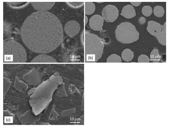
Figure 1.
SEM micrographs showing the cross section of (a) AZ91, (b) HEA and (c) SiC powders.
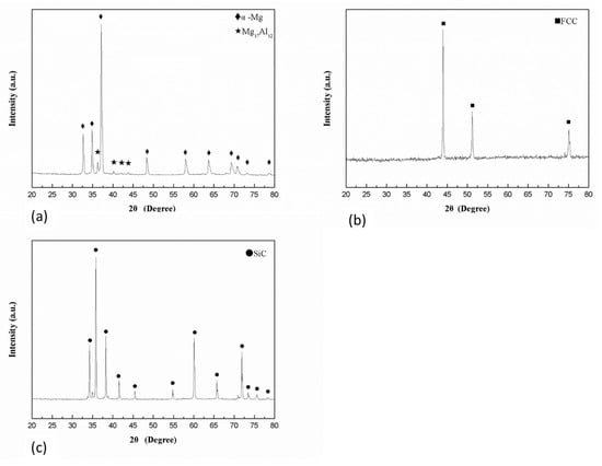
Figure 2.
XRD patterns of (a) AZ91, (b) HEA and (c) SiC powders.
3.1.2. Characterization of SPS Samples
Figure 3a shows the SEM micrograph of the sintered AZ91 sample. Pores could be seen along the particle boundary and the porosity measured by image analysis was ~1.0%. A higher magnification micrograph (Figure 3b) illustrates the microstructure of the sintered AZ91 consisting of brighter precipitates (area B) located along the boundary of gray grains (area A). By combing results from EDS and XRD analysis (Table 2 and Figure 4), the brighter precipitate was identified as the Mg17Al12 phase, and the gray grain was α-Mg. The results indicated that no phase transformation occurred in the AZ91 sample after the SPS process, and the precipitates still distributed along the grain boundary.
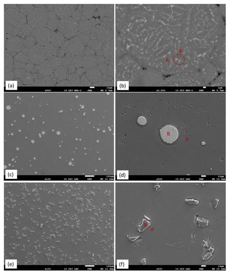
Figure 3.
SEM micrograph showing (a) particle boundaries in AZ91, (b) precipitates in Mg matrix in AZ91, (c) distribution of HEA in AZ91–HEA composite, (d) boundary of HEA particle in AZ91 matrix, (e) distribution of SiC in AZ91–SiC composite and (f) boundary of SiC particle in AZ91 matrix (EDS analysis results of area A (matrix) and B (reinforcement) are given in Table 2).
Table 2.
Composition of as-received HEA and different areas marked in AZ91–HEA and AZ91–SiC (at%).
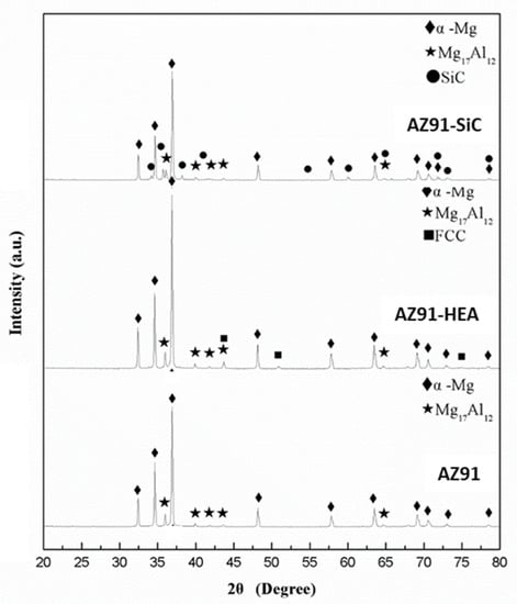
Figure 4.
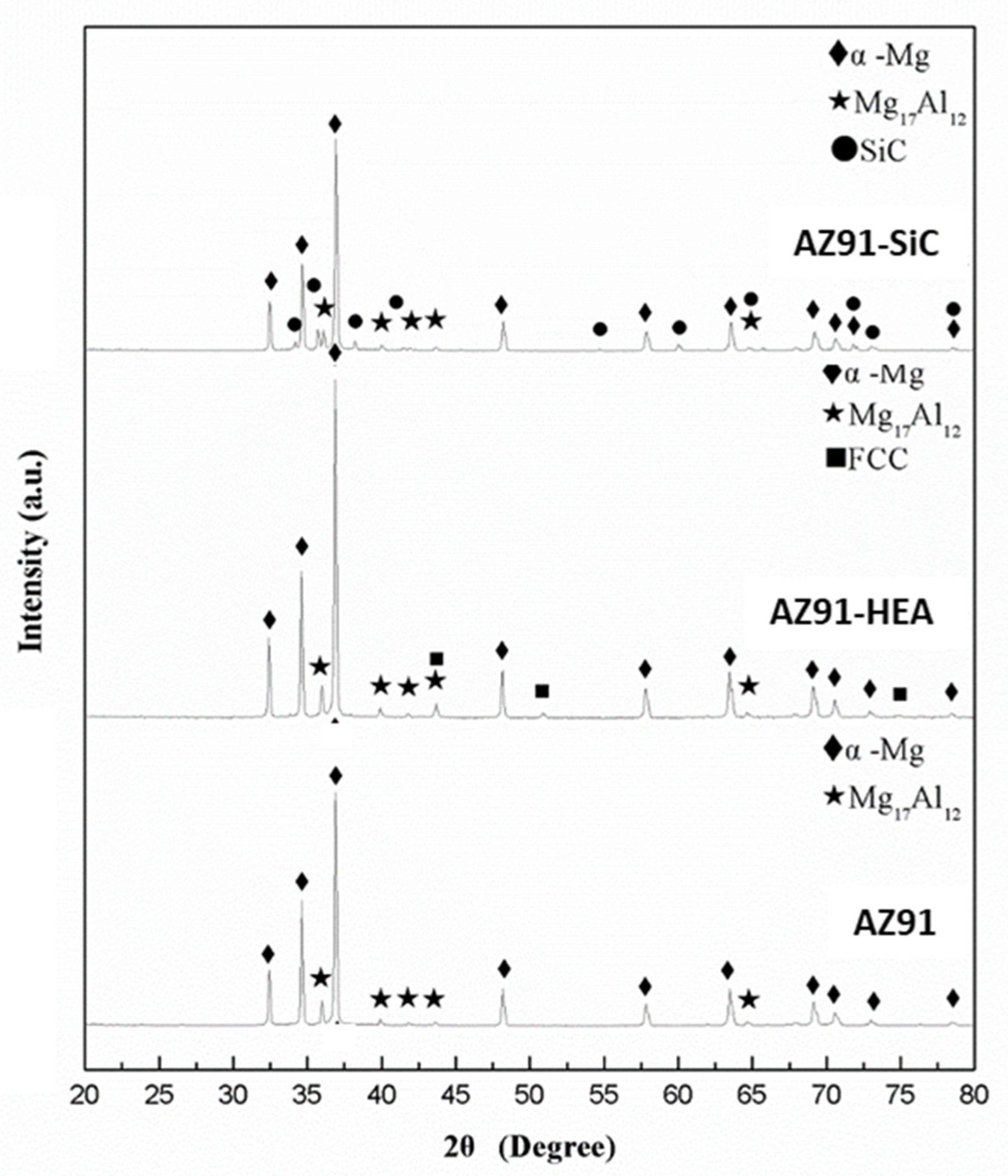
XRD patterns of AZ91, AZ91–HEA and AZ91–SiC samples.
Figure 3c shows the microstructure of the sintered AZ91–HEA composite. HEA particles distributed uniformly in the AZ91 matrix. A clear boundary between HEA particle and matrix could be seen and no interfacial reaction layer was observed (Figure 3d). The porosity in the sintered composite was 0.8%. EDS analysis results indicated that compositions of α-Mg grain (area A) and HEA (area B) were almost identical to that of α-Mg in sintered AZ91 and the composition of as-received HEA, respectively. The observation that no phase transformation occurred in the AZ91–HEA composite after SPS process was also confirmed by XRD analysis (Figure 4). HEA had a single FCC phase after SPS, and α-Mg with Mg17Al12 was still detected. Moreover, no interfacial reaction layer was observed implying there was no interdiffusion between reinforcement and matrix.
The microstructure of sintered AZ91–SiC composite showed uniformly distributed SiC particles in the AZ91 matrix (Figure 3e). No interface reaction layer was formed between reinforcement and the matrix after SPS. Combined with the results from the EDS and XRD analyses, α-Mg, Mg17Al12 and SiC were the only phases presented in the composite. No phase transformation occurred after SPS. However, the porosity of the sintered sample was 3.8%, which was four times higher than those from the sintered AZ91 and the AZ91–HEA composite.
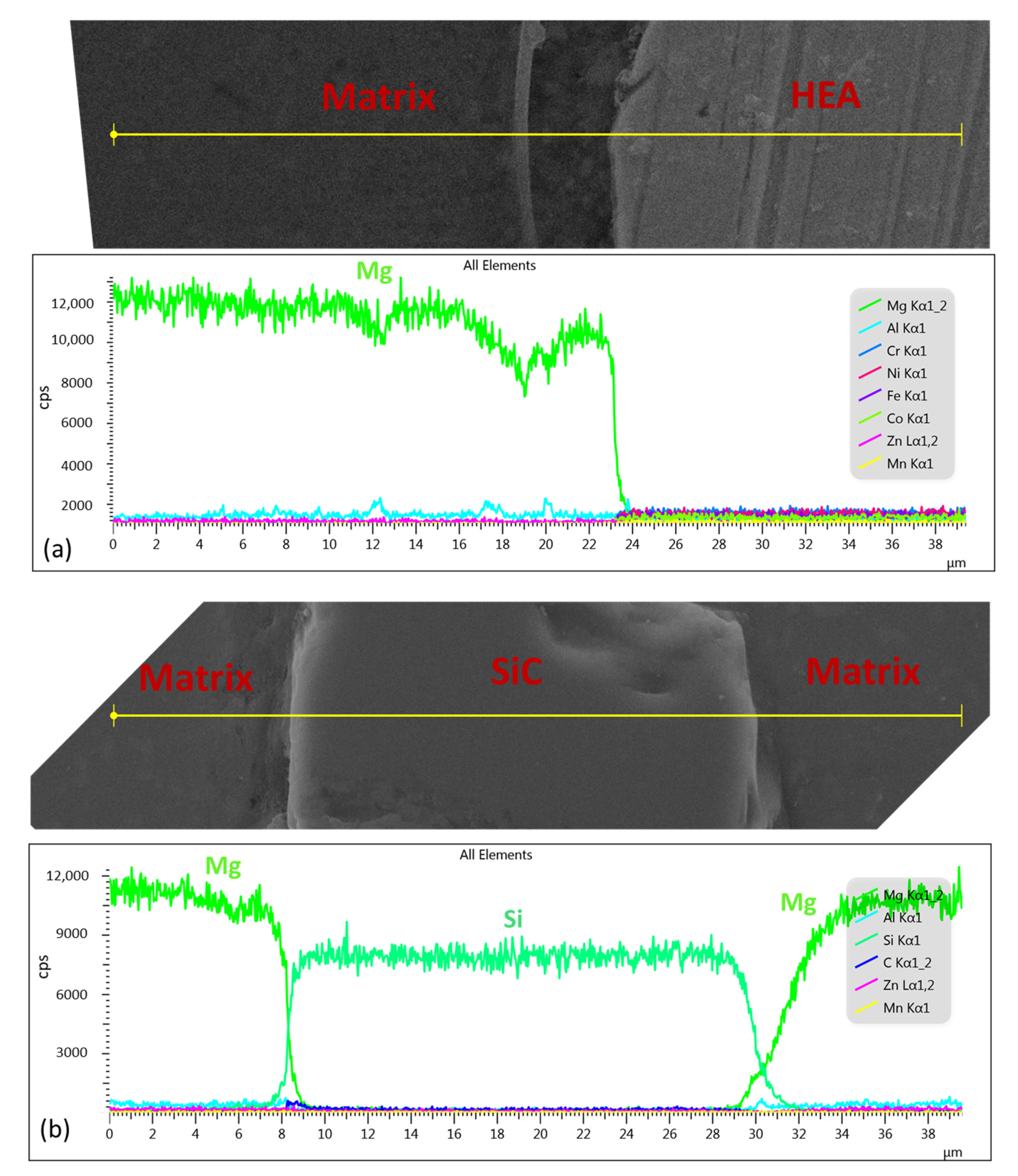
From the SEM images in Figure 3, a clear interface between the matrix and the reinforced phase HEA and SiC was observed. The compositions of the α-Mg matrix in the composites were similar to that in the AZ91 (Table 2). The composition of HEA in the sintered composite had no obvious change, compared to composition of as-received HEA powder. Moreover, from the results of the EDS line scans of HEA and SiC particles in the composites (Figure 5), no interfacial reaction layer was formed between the HEA, SiC and Mg matrix. The above results confirmed that no diffusion between the reinforced particle and the matrix occurred during the SPS process. No aggregations of reinforced particles were observed in the AZ91–HEA and AZ91–SiC composites.
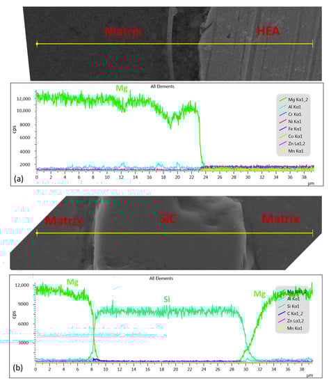
Figure 5.
EDS line scan of (a) HEA and (b) SiC in the AZ91-based composites.
3.2. Mechanical Properties of SPS Samples
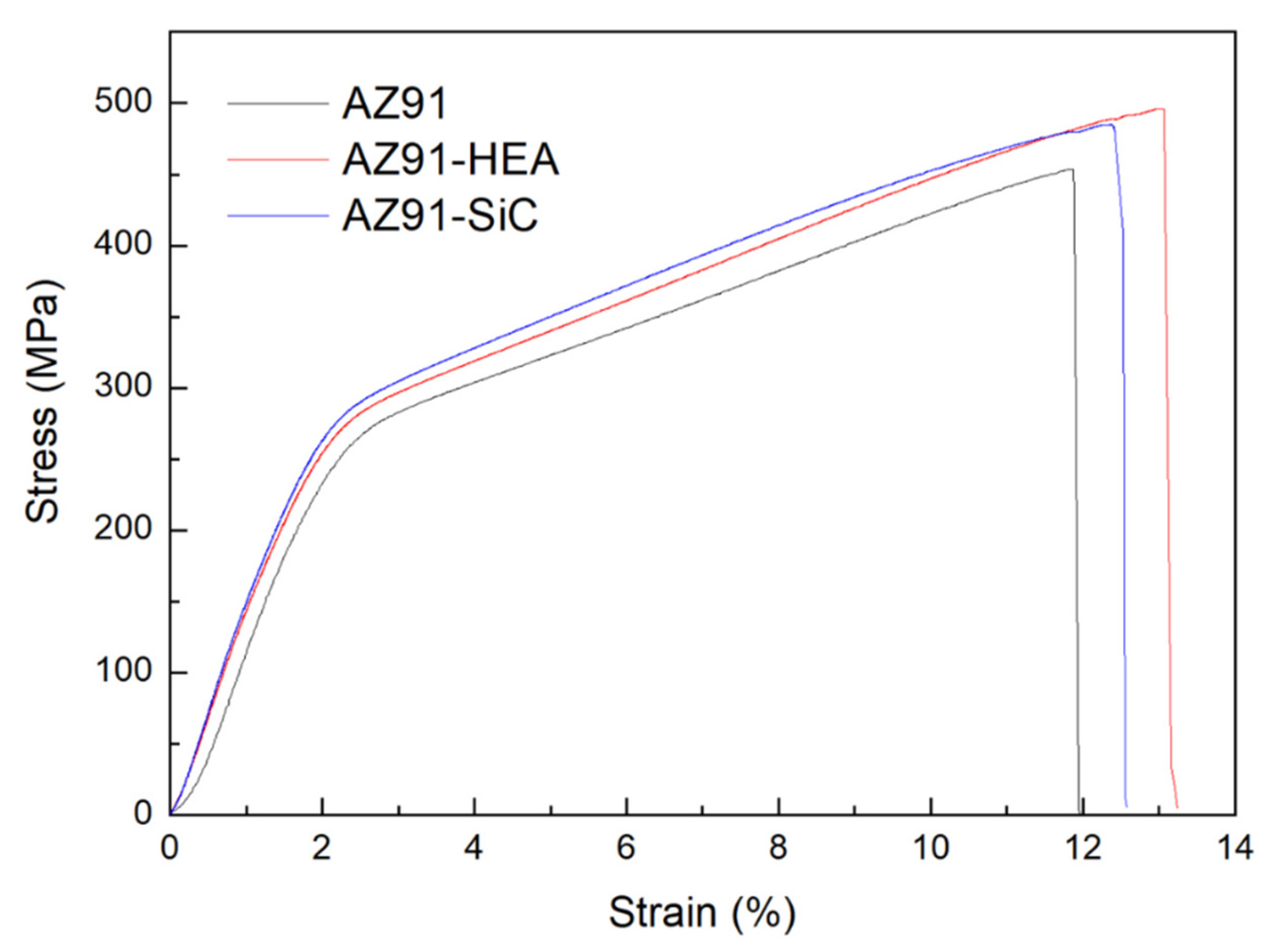
The results of engineering compressive stress-strain curves of the AZ91 alloy and the AZ91–HEA and AZ91–SiC composites are shown in Figure 6 (Enlarged sections of curves of the composites are shown in Figures S1 and S2 in Supplementary Material). The enhancement of compressive yield strength (C.Y.S), ultimate compressive strength (U.C.S.) of the AZ91 composites can be observed when compared to those of the AZ91 alloy. Figure 7 shows the strain hardening rate versus the true strain for various samples. Higher strain hardening rates were found in the AZ91 alloys reinforced with SiC and HEA. For all of the samples, the hardening occurred at the initial stage of the deformation. All samples displayed similar decreasing of work hardening tendency, indicating that behavior of plastic deformation of the alloy and composites is almost the same.
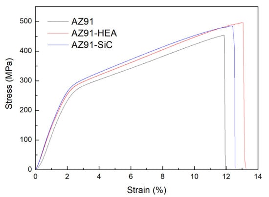
Figure 6.
Engineering compressive stress-strain curves of AZ91 alloy, AZ91–HEA and AZ91–SiC composites.
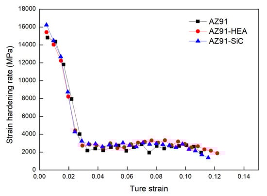
Figure 7.
Curves of strain hardening rate against true strain for AZ91 alloy, AZ91–HEA and AZ91–SiC composites.
Mechanical properties of the sintered samples are summarized in Table 3. From the summarized results of compression tests, the effect of reinforcement on the strength of composite could be observed. It could be seen that the hardness and compressive yield strength (C.Y.S) of AZ91 increased after adding 10 wt% of reinforcement. The hardness first increased from 93 HV in AZ91 to 123 HV in the AZ91–SiC composite and further increased to 138 HV in the AZ91–HEA composite. The C.Y.S increased from 178 MPa in AZ91 to 204 and to 209 MPa in AZ91–SiC and AZ91–HEA, respectively. No degradation of the failure strain was observed after the addition of HEA and SiC. The failure strain of the AZ91–SiC was similar to that of AZ91, and the failure strain of AZ91–HEA increased slightly from 12.2% to 13.7%.
Table 3.
Mechanical properties of the AZ91 alloy, AZ91–HEA and AZ91–SiC composites (Calculation of C.Y.S is given in Tables S1 and S2 in the Supplementary Materials).
4. Discussion
AZ91-based metal matrix composites reinforced by high-entropy alloys (HEA) and SiC particles were synthesized in the present study by the spark plasma sintering (SPS) process. The results from the strain hardening rate calculation show that the AZ91–HEA and AZ91–SiC composites exhibited higher strain hardening rates when compared to unreinforced AZ91 alloy (Figure 7). The dislocation densities of AZ91 and the AZ91–HEA and AZ91–SiC composites were calculated by analyzing XRD patterns and were determined to be ~3.9 × 10¹⁵ m−2 for all of the samples. The result showed that no huge difference was observed in the dislocation densities of the sintered samples, and the higher strain hardening rates in the composites were related to the reaction between reinforcements (HEA and SiC) and dislocations. The ability of HEA and SiC to increase the strain hardening rate may be attributed to the capacity to impede dislocation motion, which was also observed in other Mg-based composites reinforced with ceramic particles [26]. Moreover, other strengthening mechanisms may also contribute to the enhancement of the hardening rate.
The effect of HEA and SiC particles on the mechanical properties of the sintered composites could be discussed in terms of different strengthening mechanisms including grain boundary strengthening, Orowan strengthening, thermal mismatch strengthening, load transfer and solid solution strengthening.
The increase in the yield strength due to the refinement of the grain size of the matrix in the composites can be estimated using the following equation derived from the Hall–Petch equation [27,28]:
where k is the Hall–Petch coefficient (0.27 MPam−1/2 [29]), dcom and dAZ91 are the average grain size of Mg in the composite material and AZ91, respectively. The grain sizes of Mg in the sintered AZ91, AZ91–HEA and AZ91–SiC were 5.4, 5.3 and 5.1 μm, respectively. Only marginal changes in grain size were observed after adding HEA or SiC particles. From Equation (5), the increased yield strengths due to grain refinement in the AZ91–HEA and AZ91–SiC composites were 1 and 4 MPa, respectively. The addition of HEA and SiC particles in the composites did not cause a significant grain refinement and led to a slight increase in yield strength.
In the current study, AZ91 rather than pure Mg was used for preparing composites, implying that the matrix contained α-Mg solid solution rather than pure Mg. As a result, the effect of solid solution strengthening should be examined. Impurity atoms in solid solution can impede the movement of dislocation and increase the yield strength of the base metal. The increase in yield strength due to solid solution strengthening can be estimated using the following equation [30]:
where C equals 197 MPa [30]. Xcom and XAZ91 are the atomic percent (at%) of impurity atom in α-Mg in the composite and AZ91, respectively. The concentration of Al in Mg solid solution in AZ91, AZ91–HEA and AZ91–SiC were 7.31, 7.39 and 7.35at%, respectively. From Equation (6), Δσss in AZ91–HEA was 0.3 MPa, while that in AZ91–SiC was 0.1 MPa. The effect of solid solution strengthening led to a slightly increase in yield strength.
The contribution of Orowan strengthening to the increment in yield strength is due to the interaction of precipitates or reinforcements with dislocations, which can be calculated using the following equations [26]:
where G is the shear modulus of the matrix (16.5 GPa [31]), b is the value of the Burgers vector of the matrix (0.32 nm [30]), d is the average diameter of the precipitate or reinforced particles (28 μm for HEA and 38 μm for SiC), λ is the spacing between particles and f is the volume fraction of precipitate or reinforcement. In the AZ91-based composite, both f the precipitation of Mg17Al12 and the distribution of reinforcements such as HEA and SiC particles could contribute to the increasing yield strength. The addition of HEA and SiC into AZ91 did not change the volume fraction and size of Mg17Al12 significantly. The volume fractions of Mg17Al12 in the AZ91, AZ91–HEA and AZ91–SiC were 10, 10.2 and 11.7%, respectively. The particle size of Mg17Al12 is ~0.5 μm in all of the samples. The increasing yield strength was 8 MPa in the AZ91 alloy. After adding HEA and SiC, the values were 8.3 and 9.2 MPa, respectively. The results indicated that the contribution of Mg17Al12 on the enhancement of yield strength was similar in the AZ91 alloy and the composites. As a result, its effect could be neglected when calculating the difference between the yield strength of AZ91 and AZ91-based composites.
Regarding the strengthening due to the dispersion of HEA and SiC particles, the values were 0.10 and 0.12 MPa, respectively, indicating that the Orowan strengthening due to the dispersion of HEA and SiC particles on AZ91 matrix was not the major contributor for the increment in yield strength in the AZ91–HEA and AZ91–SiC composites. It was reported that the size of the reinforced particle had to be less than 1 μm to obtain a strong pinning effect of dislocation [32]. The coarse particle size of HEA and SiC resulted in a weak pinning effect in Orowan strengthening. The particle size of HEA and SiC has to be further refined to enhance the Orowan strengthening effect.
The thermal mismatch will lead to the generation of dislocation in the area surrounding the reinforced particles upon cooling after the SPS process and eventually increases the yield strength. The enhancement of yield strength due to the mismatch of CTE can be estimated using the following equation [33,34]:
where β is the strengthening coefficient (1.25 [34]), G is the shear modulus of matrix, b is the Burgers vector, fr is the volume fraction of reinforcement, Δα is the difference between the coefficient of thermal expansion between the matrix and the reinforcement, ΔT is the difference between the processing and testing temperatures and d is the diameter of the reinforced particles.
The coefficient of thermal expansion (CTE) of AZ91, HEA and SiC are 29 × 10−6/K, 10 × 10−6/K and 4.7 × 10⁻⁶/K, respectively. Clearly, there exists a difference between the CTE of the AZ91 matrix and the reinforcements (HEA and SiC). The increment in yield strength due to thermal mismatch in the AZ91–HEA was 10 MPa, while the increment in the AZ9–1SiC was 9.9 MPa.
In a composite material, load can be transferred from the matrix to the reinforcement particles, leading to the enhancement of yield strength. The increment in yield strength as a result of load transfer can be expressed as [34]:
where σm is the yield strength of the AZ91 alloy, and fr is the volume fraction of reinforcement. The estimated increments in yield strength in the AZ91–HEA and AZ91–SiC composite were 3 and 6 MPa, respectively.
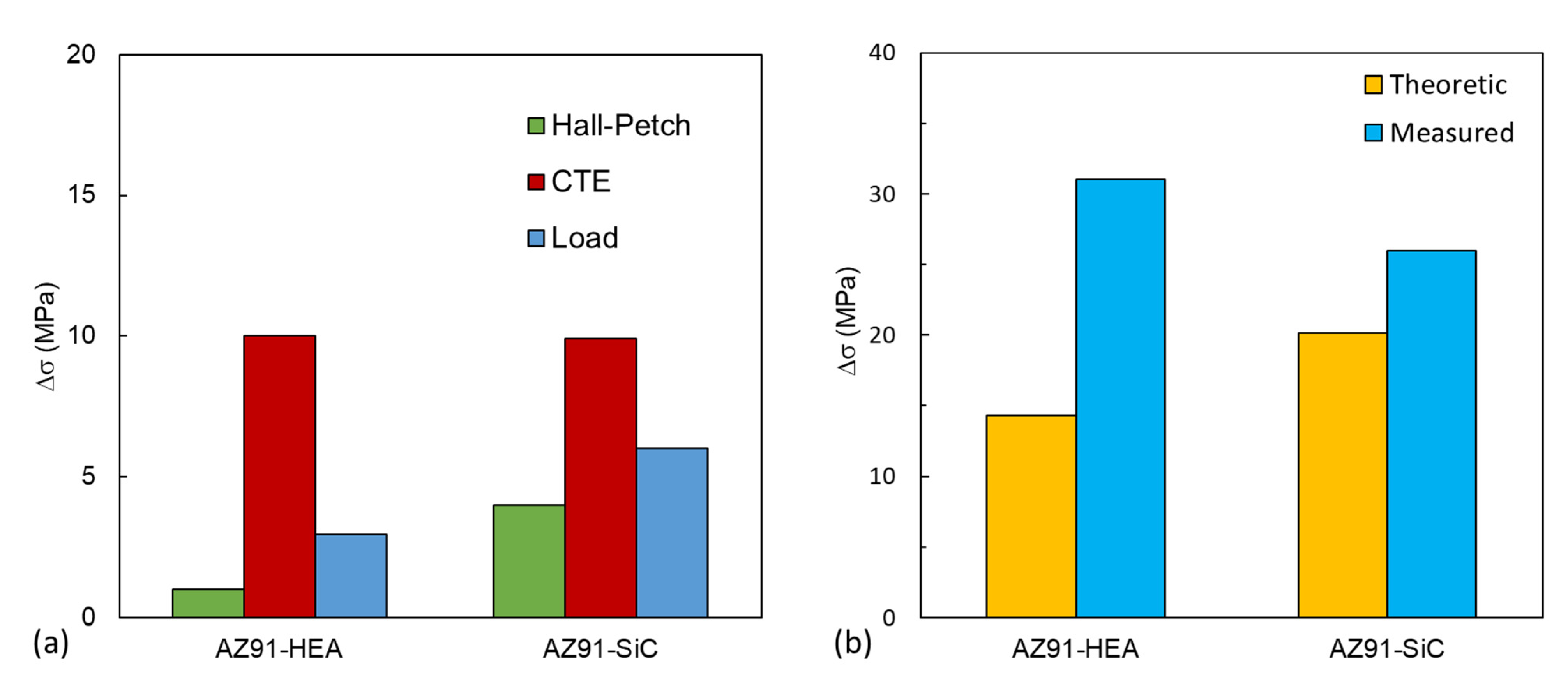
The increment in yield strength caused by different strengthening mechanisms is summarized in Table 4 and plotted in Figure 8a. In the AZ91–HEA composite, the thermal mismatch effect contributed the most (69%) to the increment in yield strength, followed by the load transfer effect (21%), the grain-refinement effect (Hall–Petch) (7%) and the Orowan effect (0.7%). A similar trend was also observed in the AZ91–SiC composite.
Table 4.
Contribution of different strengthening mechanisms to increased yield strength of AZ91 composites.

Figure 8.
(a) The increment in compressive yield strength due to the contribution of grain-size strengthening, dislocation strengthening and effect of load transfer from matrix to particle in the AZ91–HEA and AZ91–SiC composites. (b) Theoretical and measured values of the increased yield strength in the AZ91–HEA and AZ91–SiC composites.
Assuming all of the enhancement brought by various strengthening mechanisms could be added up linearly [31,35], the total increment in yield strength of AZ91-based composite estimated by different strengthening mechanisms can be expressed as:
As shown in Figure 8b, theoretical values of increment in yield strength in AZ91–HEA and AZ91–SiC composites were 14 and 20 MPa, respectively. The measured values obtained from compression tests for AZ91–HEA and AZ91–SiC were 31 and 26 MPa, respectively. The increment in yield strength could be roughly estimated using strengthening mechanisms.
According to the theoretical calculation, the addition of 10 wt% of SiC in AZ91 should have a slightly higher strengthening effect. However, the weakening effect due to higher porosity and weaker bonding between the matrix and reinforcement in AZ91–SiC composite was not taken into account in the calculation. As shown in Figure 3f, debonding was observed in the interface between the AZ91 matrix and SiC particles, implying a weaker interface bonding. The porosity in the AZ91–SiC (3.8%) is higher than that in AZ91–HEA (0.8%) and reduced the strength of the AZ91–SiC composite. It was also observed that the theoretical strength was lower than the measured strength. The deviation may be attributed to the approximate parameters used for HEA, nonuniform particle size and the assumption that irregular particles could be treated as spherical particles.
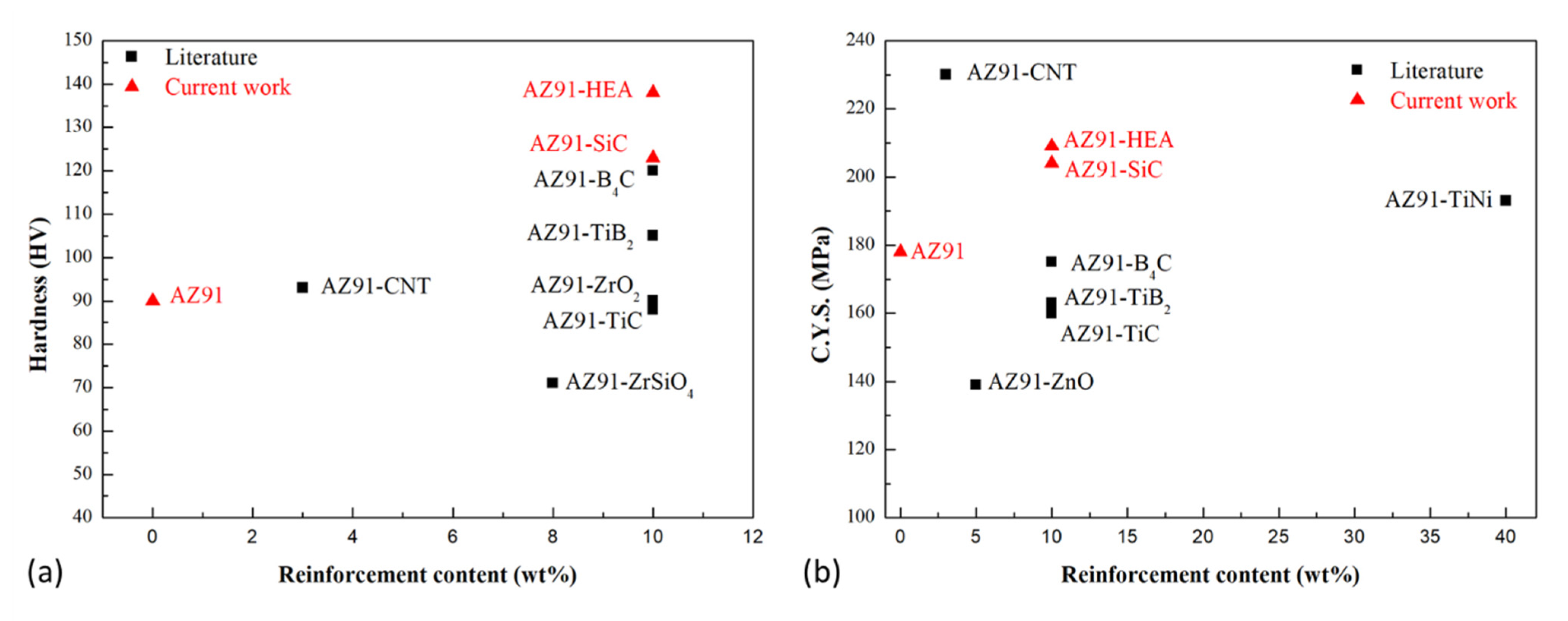
Hardness and compressive yield strength of AZ91-based metal matrix composites prepared by the powder metallurgy route in the current work and from the literature are shown in Figure 9 [35,36,37,38,39,40]. It can be seen that the hardness and strength of AZ91–HEA composite synthesized in the current work was superior to those in the AZ91-based composites reinforced with oxide, nitride and boride. The harnesses of the AZ91 matrix and HEA-reinforced particles were 84 and 208 HV, respectively. In addition to HEA’s higher hardness value compared to the matrix, its metallic nature, which resulted in a better interface bonding between the matrix and reinforcement (Figure 3e), also made HEA a promising reinforcement for the metal matrix composite.
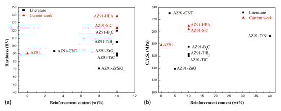
Figure 9.
(a) Hardness and (b) compressive yield strength (C.Y.S.) of AZ91 alloy and AZ91-based metal matrix composites prepared by powder metallurgy route in the current work and from literatures.
In the present study, we proposed a new approach by reinforcing AZ91 alloys with HEA particles. Preliminary results showed that the HEA particle has potential to be used for reinforcement in metal matrix composites. The analysis performed indicated that the particle size of HEA reinforcement should be refined to enhance its contribution of hardening effect of HEA. The effects of particle size, fraction of HEA and post-sintering extrusion on strength will be the subject of our future study.
5. Conclusions
In the current work, AZ91 metal matrix composites reinforced with 10 wt% of HEA particles were fabricated by spark plasma sintering process. AZ91–SiC composites were also synthesized for comparison of their mechanical properties. Microstructure and mechanical properties of the sintered composites were studied and the following conclusions could be drawn:
- AZ91–HEA composite with a uniform distribution of HEA particles in the matrix could be manufactured using spark plasma sintering process. The composite consisted of α-Mg, Mg17Al12 and FCC phase. Phase transformation was not observed in the sintered composite compared to the as-milled powder. No reaction layer was formed in the interfacial region between HEA and α-Mg matrix.
- The addition of HEA efficiently enhances hardness and compressive yield strength (C.Y.S) of AZ91–HEA. After adding HEA particles, hardness and C.Y.S of the composite were increased by 48% and 17%, respectively.
- In AZ91–HEA composite, thermal mismatch effect, load transfer effect and grain-refinement effect contributed to the increment in yield strength. Among them, the thermal mismatch effect was the major factor.
- AZ91–HEA displayed a slightly higher C.Y.S (209 MPa) than that of AZ91–SiC (204 MPa). The strengthening effect of HEA was comparable to that of the commonly used SiC reinforcement in metal matrix composite. The reason was due to the less porosity and enhanced interfacial bonding between α-Mg matrix and HEA particles.
Supplementary Materials
The following are available online at https://www.mdpi.com/article/10.3390/ma14216520/s1, Figure S1: Enlarged section of engineering compressive stress-strain curves of AZ91-HEA composite, Figure S2: Enlarged section of engineering compressive stress-strain curves of AZ91-SiC composite, Table S1: Compressive yield strength (C.Y.S) of AZ91-HEA composite calculated using stress and strain curves shown in Figure S1, Table S2: Compressive yield strength (C.Y.S) of AZ91-SiC composite calculated using stress and strain curves shown in Figure S2.
Author Contributions
Conceptualization, C.C.; methodology, C.C.; formal analysis, C.C. and H.-H.C.; investigation, C.C. and H.-H.C.; resources, C.C.; writing—original draft preparation, C.C.; writing—review and editing, C.C.; supervision, C.C.; funding acquisition, C.C. All authors have read and agreed to the published version of the manuscript.
Funding
This research was funded by Ministry of Science and Technology, Taiwan under grant number MOST 109-2221-E-011-019.
Institutional Review Board Statement
Not applicable.
Informed Consent Statement
Not applicable.
Data Availability Statement
The authors confirm that the data supporting the findings of this study are available within the article.
Acknowledgments
The authors would like to thank Shih-Hsun Chen, Nano Manufacturing and Surface Treatment Lab, NTUST for offers of the HEA materials used in this study and for suggestions. The authors would also like to thank V.K. Ranganayakulu for assisting with the spark plasma sintering.
Conflicts of Interest
The authors declare no conflict of interest.
References
- Schumann, S. The paths and strategies for increased magnesium applications in vehicles. Mater. Sci. Forum 2005, 488, 1–8. [Google Scholar] [CrossRef]
- Mordike, B.L.; Ebert, T. Magnesium: Properties-applications-potential. Mater. Sci. Eng. A 2001, 302, 37–45. [Google Scholar] [CrossRef]
- Pan, F.S.; Yang, M.B.; Chen, X.H. A review on casting magnesium alloys: Modification of commercial alloys and development of new alloys. J. Mater. Sci. Technol. 2016, 32, 1211–1221. [Google Scholar] [CrossRef]
- Cabibbo, M.; Spigarelli, S. A TEM quantitative evolution of strengthening in an Mg-RE alloy reinforced with SiC. Mater. Charact. 2011, 62, 959–969. [Google Scholar] [CrossRef]
- You, S.; Huang, Y.; Kainer, K.U.; Hort, N. Recent research and developments on wrought magnesium alloys. J. Magnes. Alloys 2017, 5, 239–253. [Google Scholar] [CrossRef]
- Nie, K.B.; Wang, X.J.; Deng, K.K.; Hu, X.S.; Wu, K. Magnesium matrix composite reinforced by nanoparticles—A review. J. Magnes. Alloy. 2021, 9, 57–77. [Google Scholar] [CrossRef]
- Wang, W.H.; Dong, C.; Shek, C.H. Bulk metallic glasses. Mater. Sci. Eng. R Rep. 2004, 44, 45–89. [Google Scholar] [CrossRef]
- Dudina, D.V.; Georgarakis, K.; Li, Y.; Aljerf, M.; LeMoulec, A.; Yavari, A.R.; Inoue, A. A magnesium alloy matrix composite reinforced with metallic glass. Compos. Sci. Technol. 2009, 69, 2734–2736. [Google Scholar] [CrossRef]
- Tsai, M.H.; Yeh, J.W. High-Entropy Alloys: A Critical Review. Mater. Res. Lett. 2014, 2, 107–123. [Google Scholar] [CrossRef]
- Miracle, D.B.; Senkov, O.N. A critical review of high entropy alloys and related concepts. Acta Mater. 2017, 122, 448–511. [Google Scholar] [CrossRef] [Green Version]
- Zhang, Y.; Zuo, T.T.; Tang, Z.; Gao, M.C.; Dahmen, K.A.; Liaw, P.K.; Lu, Z.P. Microstructures and properties of high-entropy alloys. Prog. Mater. Sci. 2014, 61, 1–93. [Google Scholar] [CrossRef]
- Muskeri, S.; Hasannaeimi, V.; Salloom, R.; Sadeghilaridjani, M.; Mukherjee, S. Small-scale mechanical behavior of a eutectic high entropy alloy. Sci Rep. 2020, 10, 2669. [Google Scholar] [CrossRef] [Green Version]
- Muskeri, S.; Choudhuri, D.; Jannotti, P.A.; Schuster, B.E.; Lloyd, J.T.; Mishra, R.S.; Mukherjee, S. Ballistic Impact Response of Al0.1CoCrFeNi High-Entropy Alloy. Adv. Eng. Mater. 2020, 22, 2000124. [Google Scholar] [CrossRef]
- Rao, J.C.; Ocelík, V.; Vainchtein, D.; Tang, Z.; Liaw, P.K.; De Hosson, J.T.M. The fcc-bcc crystallographic orientation relationship in AlxCoCrFeNi high-entropy alloys. Mater. Lett. 2016, 176, 29–32. [Google Scholar] [CrossRef] [Green Version]
- Chen, Y.X.; Zhu, S.; Wang, X.M.; Yang, B.J.; Han, G.F.; Qiu, L. Microstructure evolution and strengthening mechanism of Al0.4CoCu0.6NiSix (x = 0–0.2) high entropy alloys prepared by vacuum arc melting and copper injection fast solidification. Vacuum 2018, 150, 84–95. [Google Scholar] [CrossRef]
- Liu, Y.Y.; Chen, Z.; Chen, Y.Z.; Shi, J.C.; Wang, Z.Y.; Wang, S.; Liu, F. Effect of Al content on high temperature oxidation resistance of AlxCoCrCuFeNi high entropy alloys (x = 0, 0.5, 1, 1.5, 2). Vacuum 2019, 169, 108837. [Google Scholar] [CrossRef]
- Liang, J.T.; Cheng, K.C.; Chen, S.H. Effect of heat treatment on the phase evolution and mechanical properties of atomized AlCoCrFeNi high-entropy alloy powders. J. Alloys Compd. 2019, 30, 484–490. [Google Scholar] [CrossRef]
- Kai, W.; Cheng, F.P.; Lin, Y.R.; Chuang, C.W.; Huang, R.T.; Chen, D.; Kai, J.J.; Liu, C.T.; Wang, C.J. The oxidation behavior of Ni2FeCoCrAlx high-entropy alloys in dry air. J. Alloys Compd. 2020, 836, 155518. [Google Scholar] [CrossRef]
- Kai, W.; Cheng, F.P.; Chien, F.C.; Lin, Y.R.; Chen, D.; Kai, J.J.; Liu, C.T.; Wang, C.J. The oxidation behavior of a Ni2FeCoCrAl0.5 high-entropy superalloy in O2-containing environments. Corros. Sci. 2019, 158, 108053. [Google Scholar] [CrossRef]
- Cheng, Y.; Cui, Z.; Cheng, L.; Gong, D.; Wang, W. Effect of particle size on densification of pure magnesium during spark plasma sintering. Adv. Powder Technol. 2017, 28, 1129–1135. [Google Scholar] [CrossRef]
- Mondet, M.; Barraud, E.; Lemonnier, S.; Guyon, J.; Allain, N.; Grosdidier, T. Microstructure and mechanical properties of AZ91 magnesium alloy developed by spark plasma sintering. Acta Mater. 2016, 119, 55–67. [Google Scholar] [CrossRef]
- Mathieu, M.; Elodie, B.; Sebastien, L. Optimization of the mechanical properties of a Spark Plasma Sintered (SPS) magnesium alloy through a post-sintering in-situ precipitation treatment. J. Alloys Compd. 2017, 698, 259–266. [Google Scholar] [CrossRef]
- Liang, J.T.; Cheng, K.C.; Chen, Y.C.; Chiu, S.M.; Chiu, C.; Lee, J.W.; Chen, S.H. Comparisons of plasma-sprayed and sputtering Al0.5CoCrFeNi2 high-entropy alloy coatings. Surf. Coat. Technol. 2020, 403, 126411. [Google Scholar] [CrossRef]
- Williamson, G.K.; Hall, W.H. X-ray line broadening from filed aluminium and wolfram. Acta Metall. 1953, 1, 22–31. [Google Scholar] [CrossRef]
- Williamson, G.K.; Smallman, R.E., III. Dislocation densities in some annealed and cold-worked metals from measurements on the X-ray debye-scherrer spectrum. Philos. Mag. 1956, 1, 34–46. [Google Scholar] [CrossRef]
- Nguyen, Q.B.; Gupta, M. Enhancing compressive response of AZ31B magnesium alloy using alumina nanoparticles. Compos. Sci. Technol. 2008, 68, 2185–2192. [Google Scholar] [CrossRef]
- Armstrong, R.; Codd, I.; Douthwaite, R.M.; Petch, N.J. The plastic deformation of polycrystalline aggregate. Philos. Mag. 1962, 7, 45–58. [Google Scholar] [CrossRef]
- Sun, X.; Wang, C.; Deng, K.; Nie, K.; Zhang, X.; Xiao, X. High strength SiCp/AZ91 composite assisted by dynamic precipitated Mg17Al12 phase. J. Alloys Compd. 2018, 732, 328–335. [Google Scholar] [CrossRef]
- Caceres, C.H.; Mann, G.; Griffiths, J.R. Grain size hardening in Mg and Mg-Zn solid solutions. Metall. Mater. Trans. A 2011, 42, 1950–1959. [Google Scholar] [CrossRef] [Green Version]
- Hutchinson, C.R.; Nie, J.F.; Gorsse, S. Modeling the precipitation processes and strengthening mechanisms in a Mg-Al-(Zn) AZ91 alloy. Metal. Mater. Trans. A 2005, 36, 2093–2105. [Google Scholar] [CrossRef]
- Deng, K.; Shi, J.; Wang, C.; Wang, X.; Wu, Y.; Nie, K.; Wu, K. Microstructure and strengthening mechanism of bimodal size particle reinforced magnesium matrix composite. Compos. Part A Appl. Sci. Manuf. 2012, 43, 1280–1284. [Google Scholar] [CrossRef]
- Miller, W.S.; Humphreys, F.J. Strengthening mechanisms in particulate metal matrix composites. Scr. Metall. Mater. 1991, 25, 33–38. [Google Scholar] [CrossRef]
- Dai, L.H.; Ling, Z.; Bai, Y.L. Size-dependent inelastic behavior of particle-reinforced metal–matrix composites. Compos. Sci. Technol. 2001, 61, 1057–1063. [Google Scholar] [CrossRef]
- Goh, C.S.; Wei, J.; Lee, L.C.; Gupta, M. Properties and deformation behaviour of Mg-Y2O3 nanocomposites. Acta Mater. 2007, 55, 5115–5121. [Google Scholar] [CrossRef]
- Li, Q.; Viereckl, A.; Rottmair, C.A.; Singer, R.F. Improved processing of carbon nanotube/magnesium alloy composite. Comp. Sci. Technol. 2009, 69, 1193–1199. [Google Scholar] [CrossRef]
- Aydin, F.; Sun, Y.; Turan, M.E. The effect of TiB2 content on wear and mechanical behavior of AZ91 magnesium matrix composites produced by powder metallurgy. Powder Metall. Met. Ceram. 2019, 57, 564–572. [Google Scholar] [CrossRef]
- Aydin, F.; Sun, Y.; Turan, M.E. Influence of TiC content on mechanical, wear and corrosion properties of hot-pressed AZ91/TiC composites. J. Compos. Mater. 2019, 54, 141–152. [Google Scholar] [CrossRef]
- Aydin, F.; Sun, Y. Microstructure and wear of a sintered composite with a magnesium alloy AZ91 matrix reinforced with ZrO2 particles. Met. Sci. Heat Treat. 2019, 61, 325–329. [Google Scholar] [CrossRef]
- Mohanavel, V.; Vijay, K.; Vigneswaran, A.; Srinath, S.; Gokulnath, S. Mechanical and tribological behavior of AZ91/ZrSiO4 composites. Mater. Today 2021, 37, 1529–1534. [Google Scholar] [CrossRef]
- Kelen, F.; Gavgali, M.; Aydogmus, T. Microstructure and mechanical properties of a novel TiNi particulate reinforced AZ91 metal matrix composite. Mater. Lett. 2018, 233, 12–15. [Google Scholar] [CrossRef]


Publisher’s Note: MDPI stays neutral with regard to jurisdictional claims in published maps and institutional affiliations. |
© 2021 by the authors. Licensee MDPI, Basel, Switzerland. This article is an open access article distributed under the terms and conditions of the Creative Commons Attribution (CC BY) license (https://creativecommons.org/licenses/by/4.0/).