
Effect Steel Fibre Content on the Load-Carrying Capacity of Fibre-Reinforced Concrete Expansion Anchor


Abstract
:1. Introduction
2. Materials
2.1. Steel Anchors
2.2. Concrete Base
2.2.1. Products of Concrete Base material
2.2.2. Concrete Substrate
2.2.3. Concrete Samples
3. Methodology
3.1. Test Procedure
- (1)
- Concrete substrates with different fibre content were prepared; the description was shown in Section 2.2.2;
- (2)
- While preparing the concrete substrates, the samples are taken for compressive strength testing, see Section 2.2.3;
- (3)
- The compressive strength tests of concrete samples with different fibre content were carried out after 28 days (to determine 28-days compressive strength) and 90 days (to compare compressive strength with results of pull-out tests) according to the procedure described in Section 3.2;
- (4)
- The pull-out tests were carried out after 90 days, see Section 3.4;
- (5)
- After the pull-out tests, the boreholes were drilled from the concrete substrate and the actual fibre content of the concrete was determined according to the procedure presented in Section 3.3.
3.2. Compressive Strength of Concrete Sample
3.3. Steel Fibre Content in Concrete
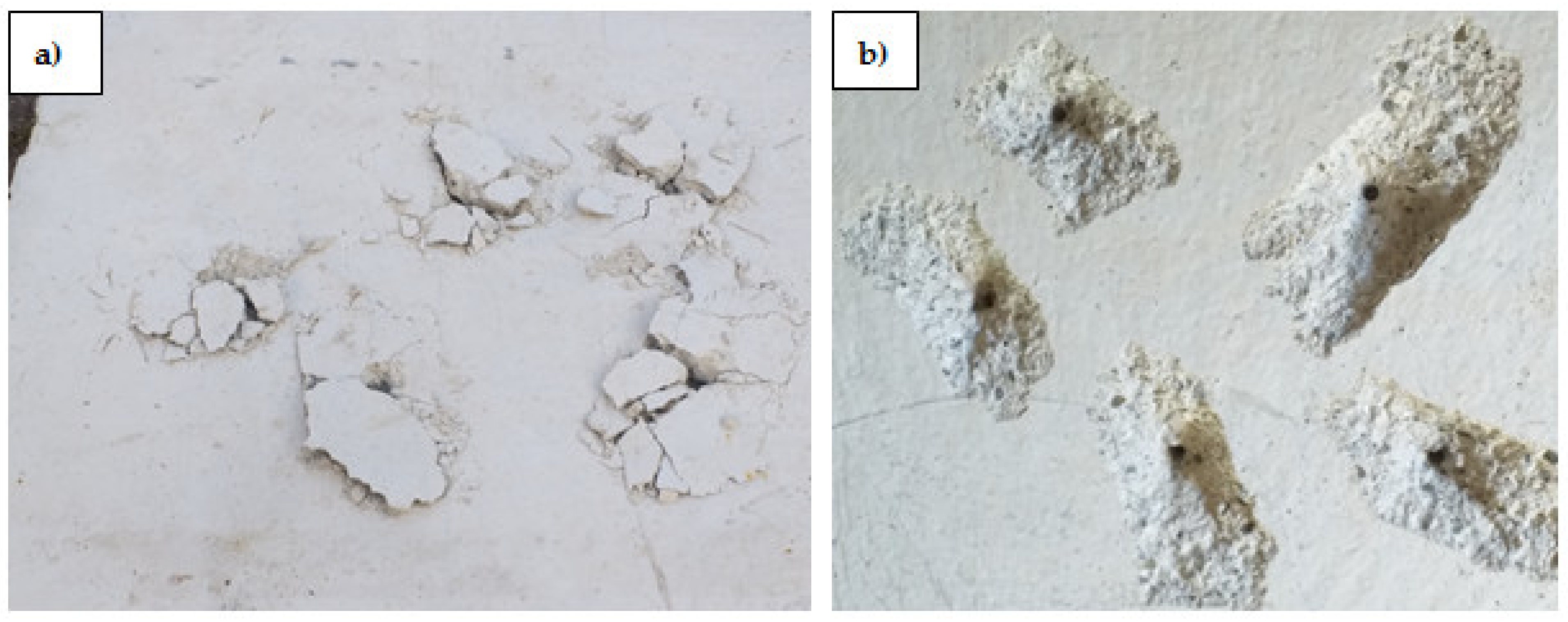
3.4. The Pull-Out Test
4. Results and Discussion
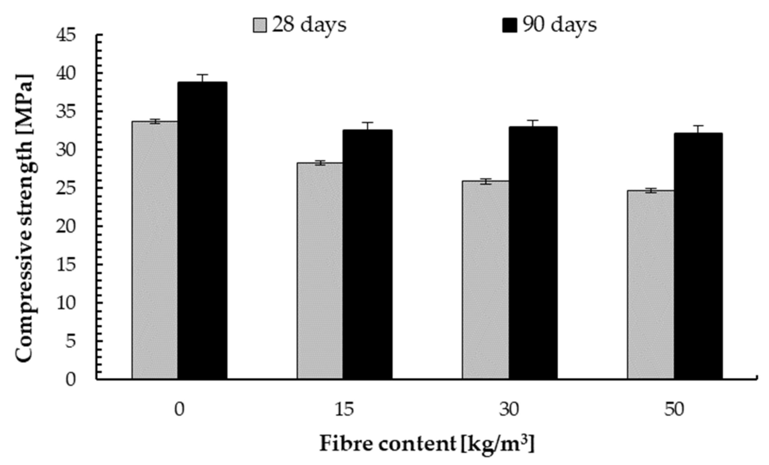
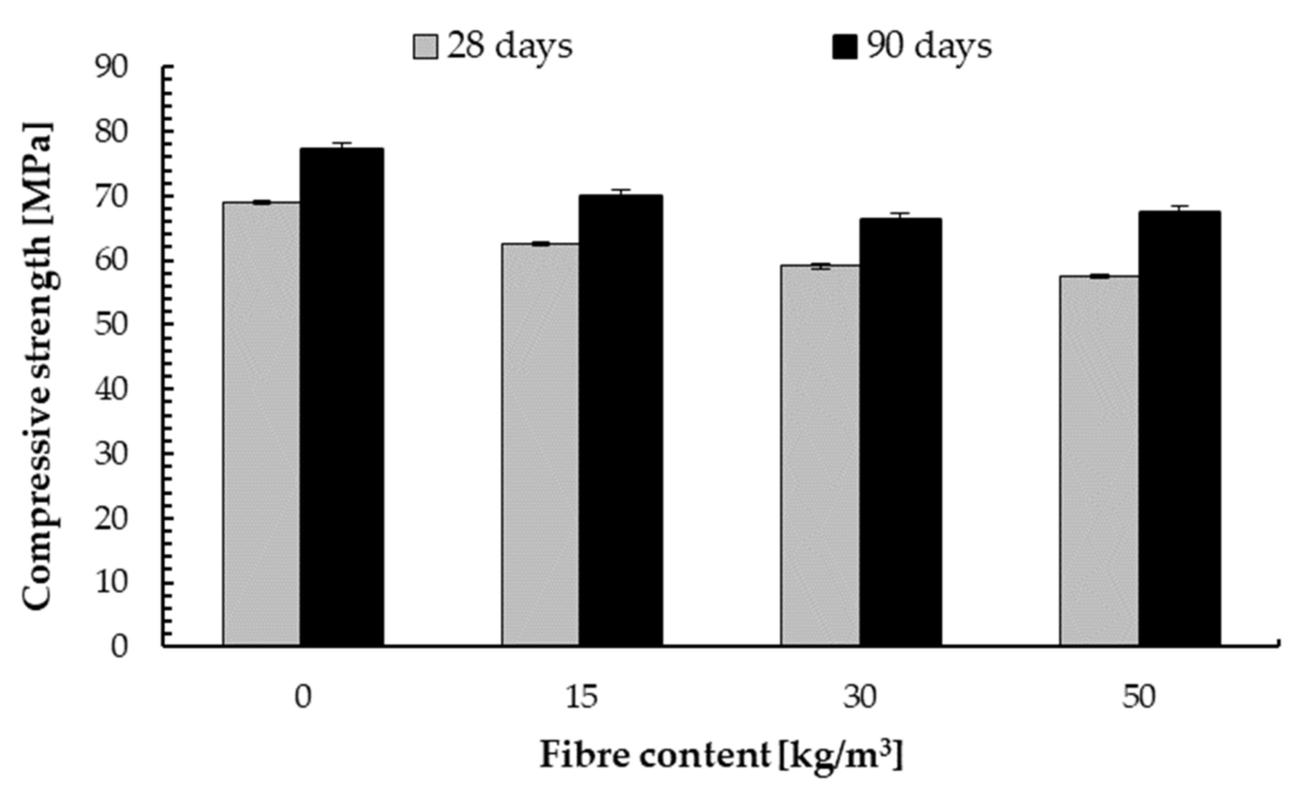
4.1. Compressive Strength
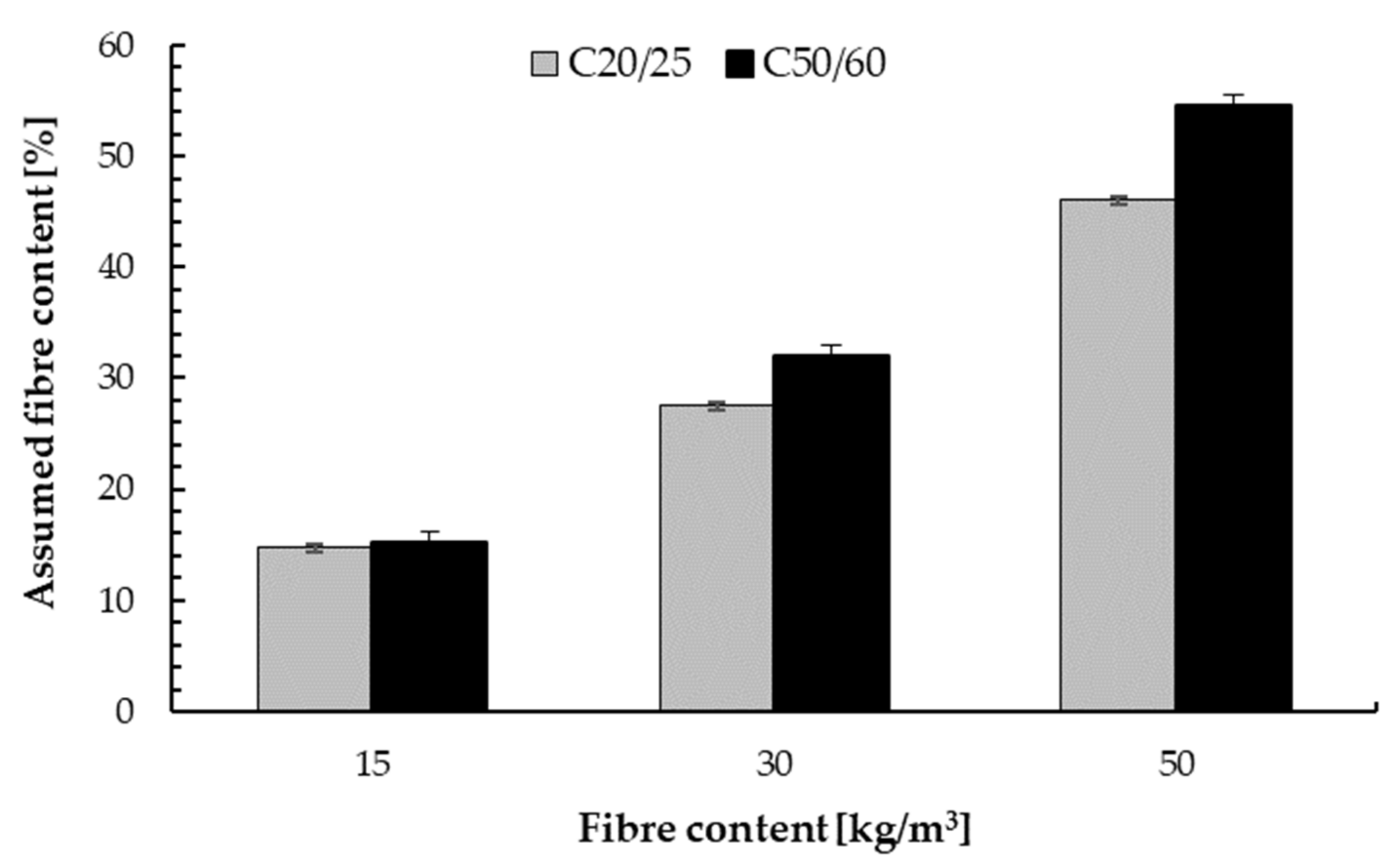
4.2. Steel Fibre Content in a Concrete Mixture
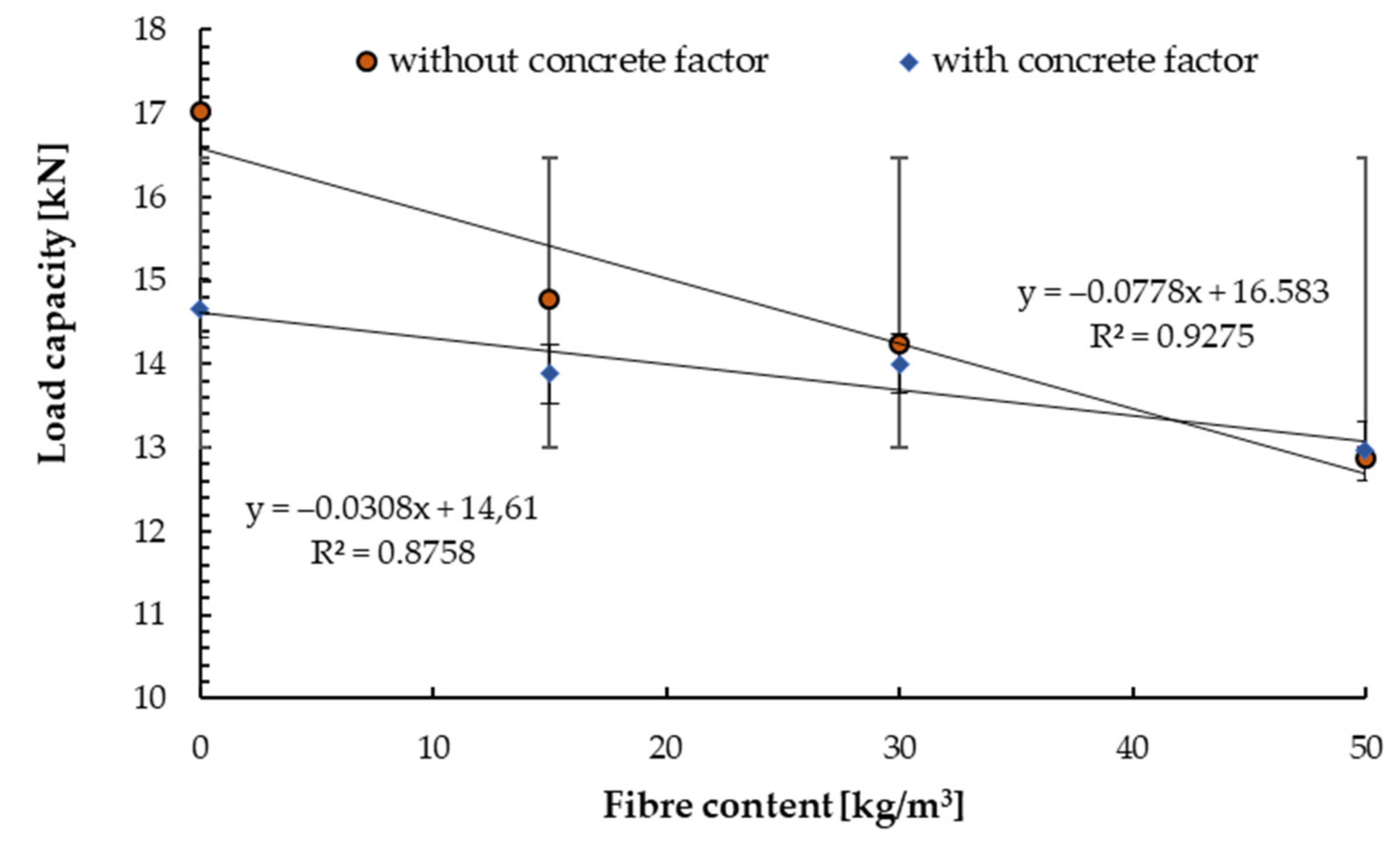
4.3. The Results of Pull-out Test
5. Summary and Conclusions
- (1)
- There were observed reductions in the compressive strength of C20/25 concrete substrates of the order of 15% for the lowest dose of steel fibres and 30% for the remaining ones, both after 28 days. After 90 days, the increase in strength was 10% compared to C20/25 concrete.
- (2)
- For concrete C50/60, there was an increase of 10% after 90 days, and the decreases resulting from the reinforcement were recorded at a maximum of 16%.
- (3)
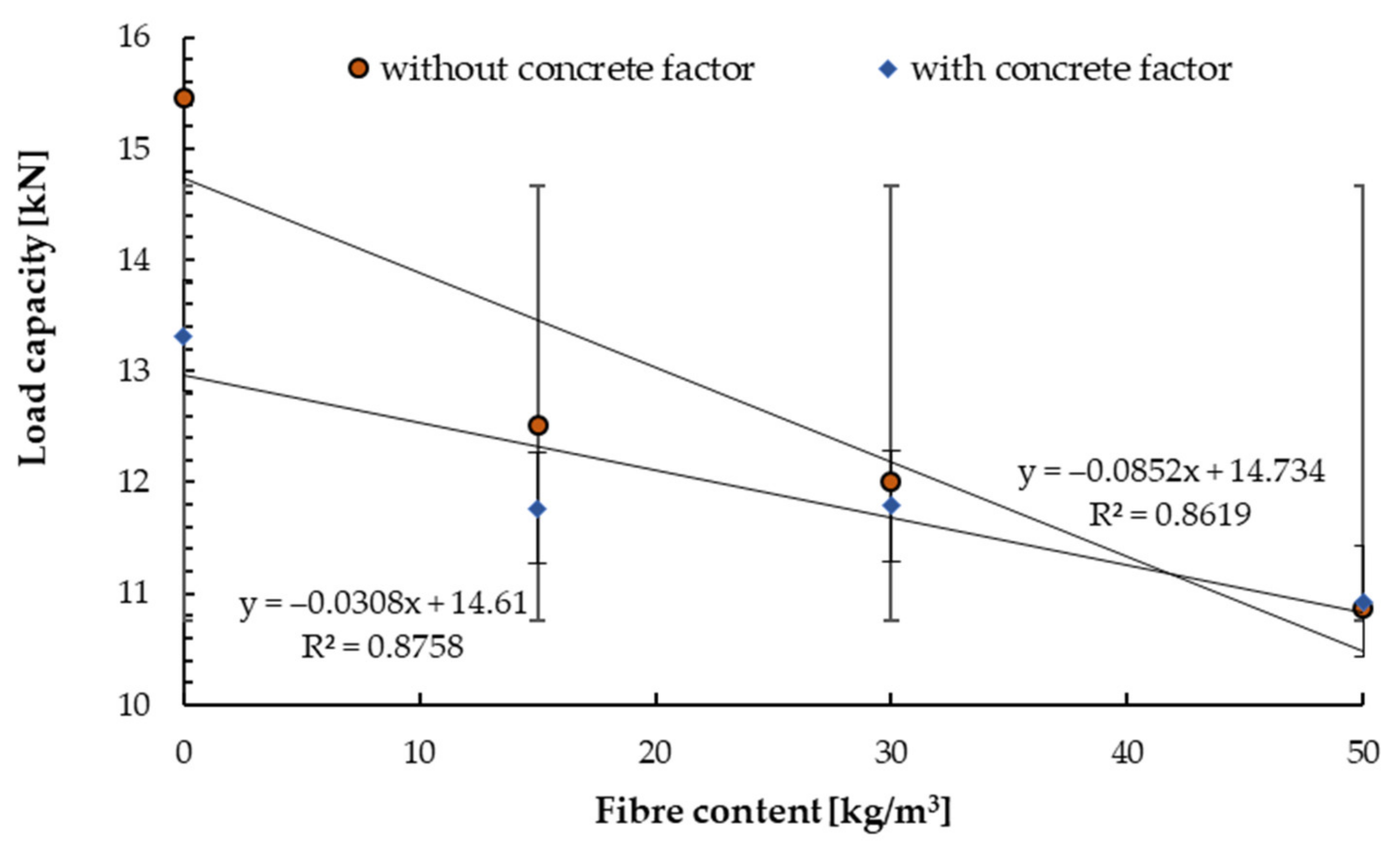
- Steelbet 50/0.8 steel fibres affect the strength of anchors using M10 expansion anchors, reducing pull-out strength.
- (4)
- The addition of fibres caused a decrease in the pull-out strength by 5% for non-cracked concrete of C20/25 class and fibre content up to 30 kg/m3 and a further 7% for the remaining specified dosage.
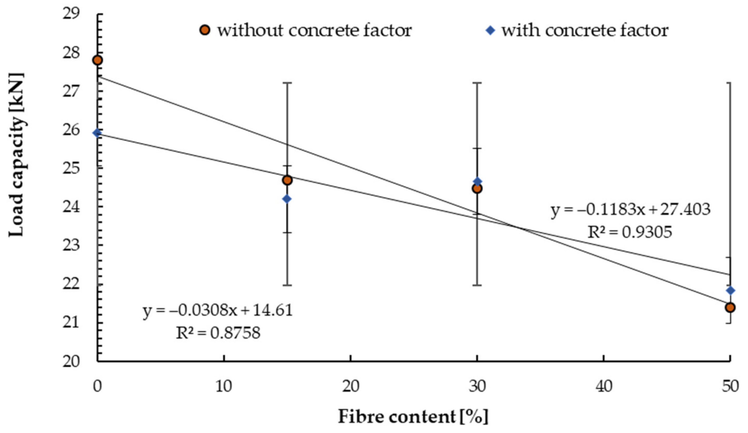
- (5)
- For cracked concrete with crack initiation cw = 0.30 mm, the reduction was from 9% to 16% in relation to non-cracked concrete and a maximum of 18% for the fibre content of 50 kg/m3.
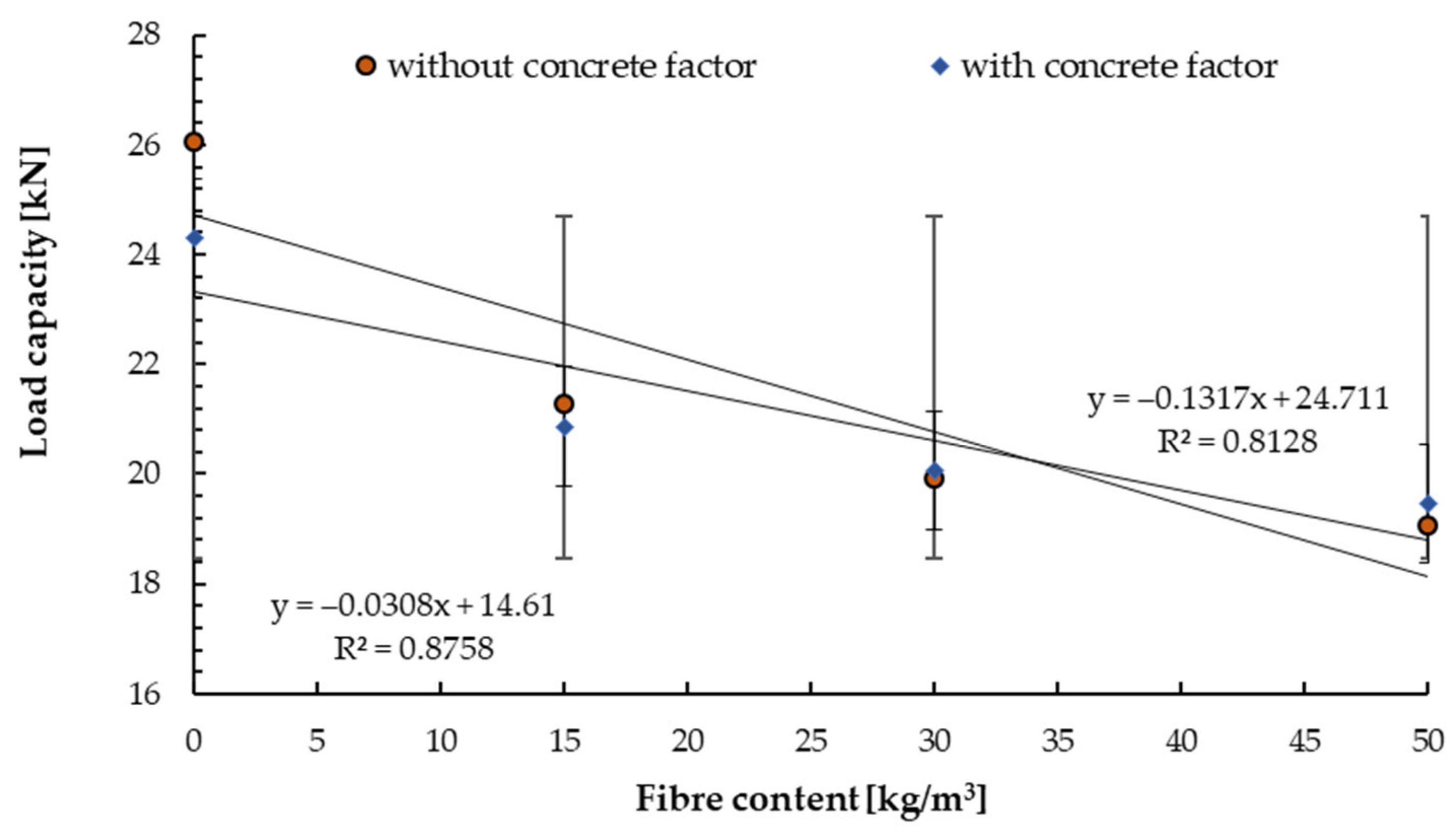
- (6)
- For concrete of the C50/60 class, a decrease in the pull-out strength of up to 20% was observed
Author Contributions
Funding
Institutional Review Board Statement
Informed Consent Statement
Data Availability Statement
Conflicts of Interest
References
- Dybel, P.; Kucharska, M. New Generation Concretes—Properties and Applications. IOP Conf. Ser. Mater. Sci. Eng. 2019, 603, 032016. [Google Scholar] [CrossRef]
- Lachemi, M.; Hossain, K.; Lambros, V.; Nkinamubanzi, P.-C.; Bouzoubaâ, N. Self-consolidating concrete incorporating new viscosity modifying admixtures. Cem. Concr. Res. 2004, 34, 917–926. [Google Scholar] [CrossRef]
- Małek, M.; Łasica, W.; Jackowski, M.; Kadela, M. Effect of Waste Glass Addition as a Replacement for Fine Aggregate on Properties of Mortar. Materials 2020, 13, 3189. [Google Scholar] [CrossRef]
- Błaszczyński, T.; Przybylska-Fałek, M. Steel Fibre Reinforced Concrete as a Structural Material. Proc. Eng. 2015, 122, 282–289. [Google Scholar] [CrossRef] [Green Version]
- Małek, M.; Jackowski, M.; Łasica, W.; Kadela, M.; Wachowski, M. Mechanical and Material Properties of Mortar Reinforced with Glass Fiber: An Experimental Study. Materials 2021, 14, 698. [Google Scholar] [CrossRef] [PubMed]
- Małek, M.; Jackowski, M.; Łasica, W.; Kadela, M. Influence of Polypropylene, Glass and Steel Fiber on the Thermal Properties of Concrete. Materials 2021, 14, 1888. [Google Scholar] [CrossRef]
- Mohammed, A.A.; Rahim, A.A.F. Experimental behavior and analysis of high strength concrete beams reinforced with PET waste fiber. Constr. Build. Mater. 2020, 244, 118350. [Google Scholar] [CrossRef]
- Małek, M.; Jackowski, M.; Łasica, W.; Kadela, M. Characteristics of Recycled Polypropylene Fibers as an Addition to Concrete Fabrication Based on Portland Cement. Materials 2020, 13, 1827. [Google Scholar] [CrossRef] [Green Version]
- Małek, M.; Łasica, W.; Kadela, M.; Kluczyński, J.; Dudek, D. Physical and Mechanical Properties of Polypropylene Fibre-Reinforced Cement–Glass Composite. Materials 2021, 14, 637. [Google Scholar] [CrossRef] [PubMed]
- Gribniak, V.; Arnautov, A.; Norkus, A.; Kliukas, R.; Tamulenas, V.; Gudonis, E.; Sokolov, A. Steel Fibres: Effective Way to Prevent Failure of the Concrete Bonded with FRP Sheets. Adv. Mater. Sci. Eng. 2016, 2016, 4913536. [Google Scholar] [CrossRef] [Green Version]
- Bonopera, M.; Chang, K.-C.; Lin, T.-K.; Tullini, N. Influence of prestressing on the behavior of uncracked concrete beams with a parabolic bonded tendon. Structur. Eng. Mechan. 2021, 77, 1–17. [Google Scholar] [CrossRef]
- Yang, J.-M.; Yoo, D.-Y.; Kim, Y.-C.; Yoon, Y.-S. Mechanical Properties of Steam Cured High-Strength Steel Fiber-Reinforced Concrete with High-Volume Blast Furnace Slag. Int. J. Concr. Struct. Mater. 2017, 11, 391–401. [Google Scholar] [CrossRef]
- Yao, J.; Zhou, Z.; Zhou, H. Highway Engineering Composite Material and Its Application; Springer: Berlin/Heidelberg, Germany, 2019. [Google Scholar]
- Kore, S.; Joshi, S. Experiments on the Workability of Steel Fiber Reinforced Concrete. In Advances in Civil Engineering and Infrastructural Development. Select Proceedings of ICRACEID 2019; Gupta, L.M., Ray, M.R., Labhasetwar, P.K., Eds.; Springer: Berlin/Heidelberg, Germany, 2021; pp. 627–635. [Google Scholar]
- Lehner, P.; Horňáková, M.; Hrabová, K. Sensitivity Analysis of Stochastic Calculation of SCC Regarding Aggressive Environment. Materials 2021, 14, 6838. [Google Scholar] [CrossRef] [PubMed]
- Shi, K.; Zhang, M.; Zhang, T.; Li, P.; Zhu, J.; Li, L. Seismic Performance of Steel Fiber Reinforced High–Strength Concrete Beam–Column Joints. Materials 2021, 14, 3235. [Google Scholar] [CrossRef]
- Jiang, F.; Deng, M.; Mo, L.; Wu, W. Effects of MgO Expansive Agent and Steel Fiber on Crack Resistance of a Bridge Deck. Materials 2020, 13, 3274. [Google Scholar] [CrossRef]
- Tóth, M.; Bokor, B.; Sharma, A. Anchorage in steel fiber reinforced concrete-concept, experimental evidence and design recommendations for concrete cone and concrete edge breakout failure modes. Eng. Struct. 2019, 181, 60–75. [Google Scholar] [CrossRef]
- Shah, A.; Ali, Q.; Alam, B.; Shahzada, K.; Khan, R.; Ahmad, N. Study on Performance Evaluation of Adhesive Anchors in Concrete. Int. J. Adv. Structur. Geotechn. Eng. 2012, 1, 74–78. Available online: https://www.researchgate.net/publication/256114896_Study_on_Performance_Evaluation_of_Adhesive_Anchors_in_Concrete (accessed on 31 October 2021).
- Hariyadi; Munemoto, S.; Sonoda, Y. Experimental Analysis of Anchor Bolt in Concrete under the Pull-Out Loading. Proc. Eng. 2017, 171, 926–933. [Google Scholar] [CrossRef]
- Nemes, R.; Lublói, É. Application of anchors under special concrete conditions. Period. Polytech. Civ. Eng. 2011, 55, 73. [Google Scholar] [CrossRef] [Green Version]
- Mahrenholtz, C.; Ayoubi, M.; Müller, S.; Bachschmid, S. Tension and shear performance of anchor channels with channel bolts cast in Fibre Reinforced Concrete (FRC). IOP Conf. Ser. Mater. Sci. Eng. 2019, 615, 012089. [Google Scholar] [CrossRef]
- Dudek, D.; Kadela, M. Pull-Out Strength of Resin Anchors in Non-cracked and Cracked Concrete and Masonry Substrates. Proc. Eng. 2016, 161, 864–867. [Google Scholar] [CrossRef] [Green Version]
- Schwenn, M.; Voit, K.; Zeman, O.; Bergmeister, K. Post-installed mechanical fasteners in high strength and ultra-high strength performance concrete. Civ. Eng. Des. 2019, 1, 161–167. [Google Scholar] [CrossRef]
- Ahmed, L.T.; Braimah, A. Behaviour of undercut anchors subjected to high strain rate loading. Proc. Eng. 2017, 210, 326–333. [Google Scholar] [CrossRef]
- Xu, X.; Tian, S. Load transfer mechanism and critical length of anchorage zone for anchor bolt. PLoS ONE 2010, 15, e0227539. [Google Scholar] [CrossRef] [PubMed]
- Giresini, L.; Puppio, M.L.; Taddei, F. Experimental pull-out tests and design indications for strength anchors installed in masonry walls. Mater. Struct. 2020, 53, 103. [Google Scholar] [CrossRef]
- Ruopp, J.; Kuhlmann, U. Steel-to-concrete joints with large anchor plates under shear loading. Steel Constr. 2017, 10, 115–124. [Google Scholar] [CrossRef]
- Luo, Y.; Wu, B. Shear performance of steel plate-concrete joints connected with anchors and adhesive. J. Adhes. 2020, 1–26. [Google Scholar] [CrossRef]
- Lee, J.-H.; Choi, E.; Cho, B.-S. Shear Failure Mode and Concrete Edge Breakout Resistance of Cast-In-Place Anchors in Steel Fiber-Reinforced Normal Strength Concrete. Appl. Sci. 2020, 10, 6883. [Google Scholar] [CrossRef]
- Bokor, B.; Tóth, M.; Sharma, A. Fasteners in Steel Fiber Reinforced Concrete Subjected to Increased Loading Rates. Fibers 2018, 6, 93. [Google Scholar] [CrossRef] [Green Version]
- Gesoglu, M.; Ozturan, T.; Özel, M.; Güneyisi, E. Tensile Behavior of Post-Installed Anchors in Plain and Steel Fiber-Reinforced Normal-and High-Strength Concretes. ACI Struct. J. 2005, 102, 224–231. Available online: https://www.concrete.org/publications/internationalconcreteabstractsportal/m/details/id/14273 (accessed on 31 October 2021).
- Mechanical Fasteners for Use in Concrete; EAD 330232-00-0601; EOTA European Assessment Document: Brussels, Belgium, 2016.
- Eurocode 2: Design of Concrete Structures—Part 4: Design of Fasteners for Use in Concrete; PN-EN 1992-4:2018-11; Polish Committee for Standardization: Warsaw, Poland, 2018.
- RILEM Technical Committee. TC-242-MDC multi-decade creep and shrinkage of concrete: Material model and structural analysis. Model B4 for creep, drying shrinkage and autogenous shrinkage of normal and high-strength concretes with multi-decade applicability. Mater. Struct. 2015, 48, 753–770. [Google Scholar] [CrossRef] [Green Version]
- Jhatial, A.A. Synergic influence of degrading mechanisms and induced loading by prestressing on the concrete: State of the art. Environ. Sci. Pollut. Res. 2021, 80, 1–15. [Google Scholar] [CrossRef] [PubMed]
- Cement—Part 1: Composition, Requirements and Compliance Criteria for Common Cements; PN-EN 197-1:2012; Polski Comitet Normalizacyjne: Warszawa, Poland, 2013.
- Cement Test Methods - Part 2: Chemical Analysis of Cement; PN-EN 196-2:2013-11; Polski Comitet Normalizacyjne: Warszawa, Poland, 2019.
- Cement Test Methods - Part 6: Determination of Grinding Degree; PN-EN 196-6:2011; Polski Comitet Normalizacyjne: Warszawa, Poland, 2011.
- Cement Test Methods - Part 6: Determination of Grinding Degree; PN-EN 196-1:2016-07; Polski Comitet Normalizacyjne: Warszawa, Poland, 2018.
- Concrete Tests - Part 2: Preparation and Maintenance of Samples for Strength Tests; PN-EN 12390-2:2019; Polski Comitet Normalizacyjne: Warszawa, Poland, 2020.
- Concrete Tests - Part 3: Compressive Strength of Test Specimens; PN-EN 12390-3:2011 + AC:2012; Polski Comitet Normalizacyjne: Warszawa, Poland, 2019.
- Steel Fiber Reinforced Concrete Test Method - Measurements of the Content of Reinforcement in Fresh and Hardened Concrete; PN-EN 14721 + A1:2007; Polski Comitet Normalizacyjne: Warszawa, Poland, 2007.
- Ding, Y.; Liu, H.; Pacheco-Torgal, F.; Jalali, S. Experimental investigation on the mechanical behaviour of the fiber reinforced high-performance concrete tunnel segment. Compos. Struct. 2011, 93, 1284–1289. [Google Scholar] [CrossRef] [Green Version]
- Serrano, R.; Cobo, A.; Prieto, M.I.; González, M.D.L.N. Analysis of fire resistance of concrete with polypropylene or steel fibers. Constr. Build. Mater. 2016, 122, 302–309. [Google Scholar] [CrossRef] [Green Version]
- Khan, Y.; Ansari, M.A.; Saroj, M.; Haider, S.; Kulkarni, S. A critical review on experimental studies of strength and durability properties of fibre reinforced Concrete composite. Int. J. Res. Eng. Technol. IJRET 2016, 5, 20–26. Available online: https://ijret.org/volumes/2016v05/i03/IJRET20160503005.pdf (accessed on 5 December 2021).
- Afroughsabet, V.; Ozbakkaloglu, T. Mechanical and durability properties of high-strength concrete containing steel and polypropylene fibers. Constr. Build. Mater. 2015, 94, 73–82. [Google Scholar] [CrossRef]
- Köksal, F.; Altun, F.; Yiğit, I.; Şahin, Y. Combined effect of silica fume and steel fiber on the mechanical properties of high strength concretes. Constr. Build. Mater. 2008, 22, 1874–1880. [Google Scholar] [CrossRef]
- Murali, G.; Santhi, A.S.; Ganesh, G.M. Effect of Crimped and Hooked End Steel Fibres on the Impact Resistance of Concret. J. Appl. Sci. Eng. 2014, 17, 259–266. [Google Scholar] [CrossRef]
- Song, P.S.; Hwang, S. Mechanical properties of high-strength steel fiber-reinforced concrete. Constr. Build. Mater. 2004, 18, 669–673. [Google Scholar] [CrossRef]
- Marcalikova, Z.; Mateckova, P.; Racek, M.; Bujdos, D. Study on Shear Behavior of Steel Fiber Reinforced Concrete Small Beams. Proc. Struct. Integr. 2020, 28, 957–963. [Google Scholar] [CrossRef]
- Falliano, D.; De Domenico, D.; Ricciardi, G.; Gugliandolo, E. Compressive and flexural strength of fiber-reinforced foamed concrete: Effect of fiber content, curing conditions and dry density. Constr. Build. Mater. 2019, 198, 479–493. [Google Scholar] [CrossRef]
- Farhat, M.; Issa, M.; Prado, B.F.J. Pull-Out Behavior of Headed Anchors Used in a Totally Prefabricated Counterfort Retaining Wall System. PCI J. 2019, 64, 81–98. [Google Scholar] [CrossRef]
- Czarnecki, R.M.; Manrique, M.A.; Samaddar, S.K. Ultimate Load Capacities of Expansion Anchor Bolts. J. Energy Eng. 1993, 119, 139–158. [Google Scholar] [CrossRef]

| Length Lw [mm] | Drill Diameter d0 [mm] | Nut Diameter dp [mm] | Tensile Strength Rm [MPa] |
|---|---|---|---|
| 140 | 10 | 17 | 680 |
| Component-Material | Drill Depth h1 [mm] | Embedment Depth hnom [mm] | Effective Depth hef [mm] | Nominal Torque Tinst [Nm] |
|---|---|---|---|---|
| Anchor body–carbon steel Expansion sleeve–Stainless steel A4 Hexagonal nut–Steel class 8 EN ISO 898-2 Washer–Steel DIN 125 Protection–coating (≥5 μm) acc. to EN ISO 4042 | 54 | 49 | 40 | 30 |
| Compositions | SiO2 | Al2O3 | Fe2O3 | CaO | MgO | SO3 | Na2O | K2O | Cl | LOI | IR |
|---|---|---|---|---|---|---|---|---|---|---|---|
| Unit (vol.%) | 19.5 | 4.9 | 2.9 | 63.3 | 1.3 | 2.8 | 0.1 | 0.9 | 0.05 | 2.48 | 0.63 |
| Properties | Specific Surface Area [m2/kg] | Specific Gravity [kg/m3] | Compressive Strength [MPa] | |
|---|---|---|---|---|
| Materials | After 2 Days | After 28 Days | ||
| Cement | 3840 | 3060 | 28.0 | 58.0 |
| Length of Fibre L [mm] | Length l [mm] | Diameter d [mm] | Height h [mm] | Tensile Strength Rm [MPa] |
|---|---|---|---|---|
| 50 | 4.0 | 0.8 | 3.0 | 1100 |
| Components | Concrete | ||
|---|---|---|---|
| C20/25 | C50/60 | ||
| [kg/m3] | |||
| CEM I 42.5 R (Górażdże, Poland) | 230 | 420 | |
| Silica fume 2/8 (KSM, Poland) | 380 | 464 | |
| Silica fume 8/16 (KSM, Poland) | 830 | 645 | |
| Quartz sand 0/2 (KSM, Poland) | 770 | 622 | |
| MasterPozzolith BV 18 C (BASF, Poland) | 0.92 | — | |
| Sikament 400/30 (Sika, Poland) | 1.72 | — | |
| Sika ViscoCrete-3088 M (Sika, Poland) | — | 2.52 | |
| Water | 140 | 182 | |
Publisher’s Note: MDPI stays neutral with regard to jurisdictional claims in published maps and institutional affiliations. |
© 2021 by the authors. Licensee MDPI, Basel, Switzerland. This article is an open access article distributed under the terms and conditions of the Creative Commons Attribution (CC BY) license (https://creativecommons.org/licenses/by/4.0/).
Share and Cite
Dudek, D.; Kadela, M.; Małek, M. Effect Steel Fibre Content on the Load-Carrying Capacity of Fibre-Reinforced Concrete Expansion Anchor. Materials 2021, 14, 7757. https://doi.org/10.3390/ma14247757
Dudek D, Kadela M, Małek M. Effect Steel Fibre Content on the Load-Carrying Capacity of Fibre-Reinforced Concrete Expansion Anchor. Materials. 2021; 14(24):7757. https://doi.org/10.3390/ma14247757
Chicago/Turabian StyleDudek, Daniel, Marta Kadela, and Marcin Małek. 2021. "Effect Steel Fibre Content on the Load-Carrying Capacity of Fibre-Reinforced Concrete Expansion Anchor" Materials 14, no. 24: 7757. https://doi.org/10.3390/ma14247757
APA StyleDudek, D., Kadela, M., & Małek, M. (2021). Effect Steel Fibre Content on the Load-Carrying Capacity of Fibre-Reinforced Concrete Expansion Anchor. Materials, 14(24), 7757. https://doi.org/10.3390/ma14247757