Article

Effect of Annealing on the Structural, Magnetic and Surface Energy of CoFeBY Films on Si (100) Substrate

1
Department of Materials Science and Engineering, I-Shou University, Kaohsiung 840, Taiwan
2
Bachelor Program in Industrial Technology, National Yunlin University of Science and Technology, 123 University Road, Section 3, Douliou, Yunlin 64002, Taiwan
3
Graduate School of Materials Science, National Yunlin University of Science and Technology, 123 University Road, Section 3, Douliou, Yunlin 64002, Taiwan
4
Institute of Physics, Academia Sinica, Nankang, Taipei 11529, Taiwan
*
Author to whom correspondence should be addressed.
Materials 2021, 14(4), 987; https://doi.org/10.3390/ma14040987
Submission received: 26 January 2021 / Revised: 11 February 2021 / Accepted: 17 February 2021 / Published: 19 February 2021

Abstract

:
The structure, magnetic properties, optical properties and adhesion efficiency of CoFeBY films were studied. Co40Fe40B10Y10 alloy was sputtered onto Si (100) with a thickness of 10–50 nm, and then annealed at room temperature, 100 °C, 200 °C and 300 °C for 1 h. X-ray diffraction (XRD) showed that the CoFeBY films deposited at room temperature are amorphous. Annealing at 100 °C gave the films enough thermal energy to change the structure from amorphous to crystalline. After annealing, the CoFeBY thin film showed a body-centered cubic (BCC) CoFeB (110) characteristic peak at 44°. However, the low-frequency alternative-current magnetic susceptibility (χac) and saturation magnetization (MS) increased with the increase of thickness. CoFeBY thin films had the highest χac and MS after annealing at 300 °C compared to that at other temperatures. After annealing at 300 °C, the surface energy of CoFeBY film is the maximum at 50 nm. Higher surface energy indicated stronger adhesion.

1. Introduction

Magnetic nanomaterials have attracted more and more attention in recent years owing to their unique magnetism and potential applications in data storage. Among the magnetic metals, the CoFeB alloy is a kind of soft magnetic material with high saturation magnetization (MS) and low coercivity (Hc). The CoFeB has received much attention; the development of its ferromagnetic (FM)/antiferromagnetic (AFM) exchange-biasing anisotropy has increased the tunneling magnetoresistance (TMR) and enhanced the magnetic anisotropy of the structure [1,2,3,4,5]. The CoFeB thin film can also be used as a free layer or a pinned layer to form a magnetic tunnel junction (MTJ) with the MgO layer. In addition, CoFeB materials also attracted special attention in different applications. Among other uses, sensor applications of the materials in which induced magnetic anisotropy occurs are very important. It was shown that stress of field induced magnetic anisotropy can be formed in such materials and their high frequency applications are demonstrated [6,7]. The annealed CoFeB film exhibits B diffusion and develops perpendicular magnetic anisotropy [8,9,10,11]. Therefore, CoFeB thin films can be used as potential materials for magnetoresistance random access memory (MRAM), read/write heads and hard disk devices. The magnetic properties of a material are influenced by its thickness, shape, crystallinity and interface interaction. Often, improvements in TMR values of the CoFeB/MgO structure are required to improve TMR ratios. When the crystallization temperature is higher than that of the sample, the nanocrystalline structure exhibits excellent soft magnetic properties, which is related to the strong intergranular magnetic exchange mediated by a ferromagnetic amorphous matrix. The tunneling magnetoresistance (TMR) of CoFeB-type MTJ changes when the amorphous state changes to nanocrystalline. However, annealing at 350 °C or higher not only reduces the TMR ratios but also causes the loss of magnetic properties due to an excessively high annealing temperature [12,13,14]. Therefore, the magnetic characteristics of CoFeB films at room temperature (RT) or in an annealing environment have been the focus of several studies. Rare earth elements have very unique characteristics that can be used to improve the high-temperature resistance, including their mechanical strength and other physical properties of magnetic films. Perhaps the rare earth elements can be used to enhance and solve the thermal stability of magnetic films at high temperatures. The element yttrium (Y) has a high abundance in rare earth ore, but it has been much less utilized. The addition of Y to the alloy matrix and heat treatment significantly improves mechanical properties such as thermal stability and corrosion resistance [15]. Y substitution can also enhance the exchange coupling effect, which not only improves the remanence and magnetic energy of the product, but also improves the thermal stability of the product [16,17,18,19]. When Y is added to soft magnetic materials, such as Fe-Y-B alloy, it is necessary to increase the soft magnetic performance through some methods such as low-temperature annealing, because Y has hard magnetic properties [20,21,22]. However, the effect of the addition of Y to CoFeB is not fully documented. It would be interesting to study the effect of the addition of the rare earth element Y to the CoFeB alloy, perform thermal annealing and examine the magnetic properties of the CoFeB film. Therefore, it is great significance to investigate the characteristics of CoFeBY films deposited by sputtering technique through RT and post-annealing treatments. The different thickness (tf) of as-deposited and annealed CoFeBY films were also studied and we investigated the effects of crystallinity on the magnetic properties, adhesion and optical performance of the films. In our previous study, the properties of as-deposited Glass/CoFeBY and Si (100)/CoFeBY films were studied, as shown in Table 1 [23,24]. Continuing forward, we studied the as-deposited and annealed CoFeBY thin films. We found that the low-frequency alternate-current magnetic susceptibility (χac) ranges of CoFeBY films were higher than those of other Glass/CoFeVB and Si (100)/CoFeVB materials.

2. Materials and Methods

CoFeBY thin films with a thickness of 10–50 nm were sputtered onto Si (100) substrates by direct current (DC) magnetron sputtering at room temperature (RT). The films were prepared under the following four conditions: (a) at room temperature, (b) annealed at 100 °C for 1 h, (c) annealed at 200 °C for 1 h and annealed at 300 °C for 1 h. The power density was 1.65 W/cm2 and the deposition rate was 1.2 nm/min. The chamber base pressure was 3 × 10⁻⁷ Torr, and the Ar working pressure was 3 × 10⁻³ Torr. The pressure in an ex-situ annealed condition was 2.5 × 10⁻³ Torr with a specific Ar gas. The alloy target for the composition of CoFeBY was 40 at% Co, 40 at% Fe, 10 at% B and 10 at% Y. The grazing incidence X-ray diffraction (GIXRD) patterns of Cukα1 (PAN analytical X’pert PRO MRD, Malvern Panalytical Ltd, Cambridge, UK) and low angle diffraction incidence of about 2° were used to determine the structure of CoFeBY films. The in-plane low-frequency alternate-current magnetic susceptibility (χac) and hysteresis loop of Co40Fe40B10Y10 films have been studied by using χac analyzer (XacQuan, MagQu Co. Ltd., New Taipei City, Taiwan) and alternating gradient magnetometer (AGM, PMC, Ohio, OH, USA). The standard sample was calibrated by external magnetic field χac measurement. The sample was inserted into the χac analyzer. The range of driving frequency was between 10 and 25,000 Hz. χac was determined by magnetization. All specimens had the same shape and size to eliminate demagnetization. The χac valve is an arbitrary unit (a.u.) which due to exchange result corresponded to the reference standard sample, which is a comparative value. The relationship between magnetic susceptibility and frequency was measured by the χac measurement. The optimal resonance frequency (fres) was detected by χac analyzer, which reveals the frequency of the maximum χac. The contact angle of CoFeBY film was measured with deionized water and glycerol. The accuracy of each contact angles is measured by three times. The contact angle was an averaged value. The surface energy was obtained from the contact angle and some calculations [25,26,27].

3. Results

3.1. Structure Property and Grain Size Distribution

Figure 1a–d show the X-ray diffraction (XRD) pattern of the as-deposited and annealed CoFeBY thin films.
The Si (100) substrate used in this study had strong diffraction peaks at 33.2° and 70°; therefore, the XRD was displayed at a diffraction angle (2θ) between 35 and 60 degrees. There was no obvious crystallization peak, indicating the amorphousness of thin films deposited at RT and annealed 100 °C at 10 nm thickness. Therefore, the thickness of the CoFeBY thin films may be considered as a discontinuous growth model where random atomic arrangements lead to an amorphous state. At an annealing temperature of 100 °C and 20 nm thickness, the structure could transform from an amorphous state to a crystalline state. XRD intensity data shows the characteristic peak at around 2θ = 44°, as shown in Figure 1b–d, which is attributed to the CoFeB with body-centered-cubic structure (110) orientation. Further annealing at temperatures higher than 100 °C relieved stresses and caused a loss of tensile stresses, as is obvious from the slight shift of the CoFeB peak to the left, attributed to the annealing effect. Bragg’s law applied due to the expansion of lattice parameters, resulting in the replacement of larger atoms in the matrix. This indicates that the lattice parameter expands due to the inclusion of Y atoms. Although the chamber was pumped to 10±7 Torr in the sputtering system, oxygen may still be present. Both natural oxides on Si (100) substrate and oxygen contamination on a sputtering target contributed to the formation of YFeO3. The full width at half maximum (FWHM) measured by XRD was used to calculate the grain size by the Scherrer equation.
Scherrer′s formula (Equation (1)) is [28],
D = kλ/βcosθ
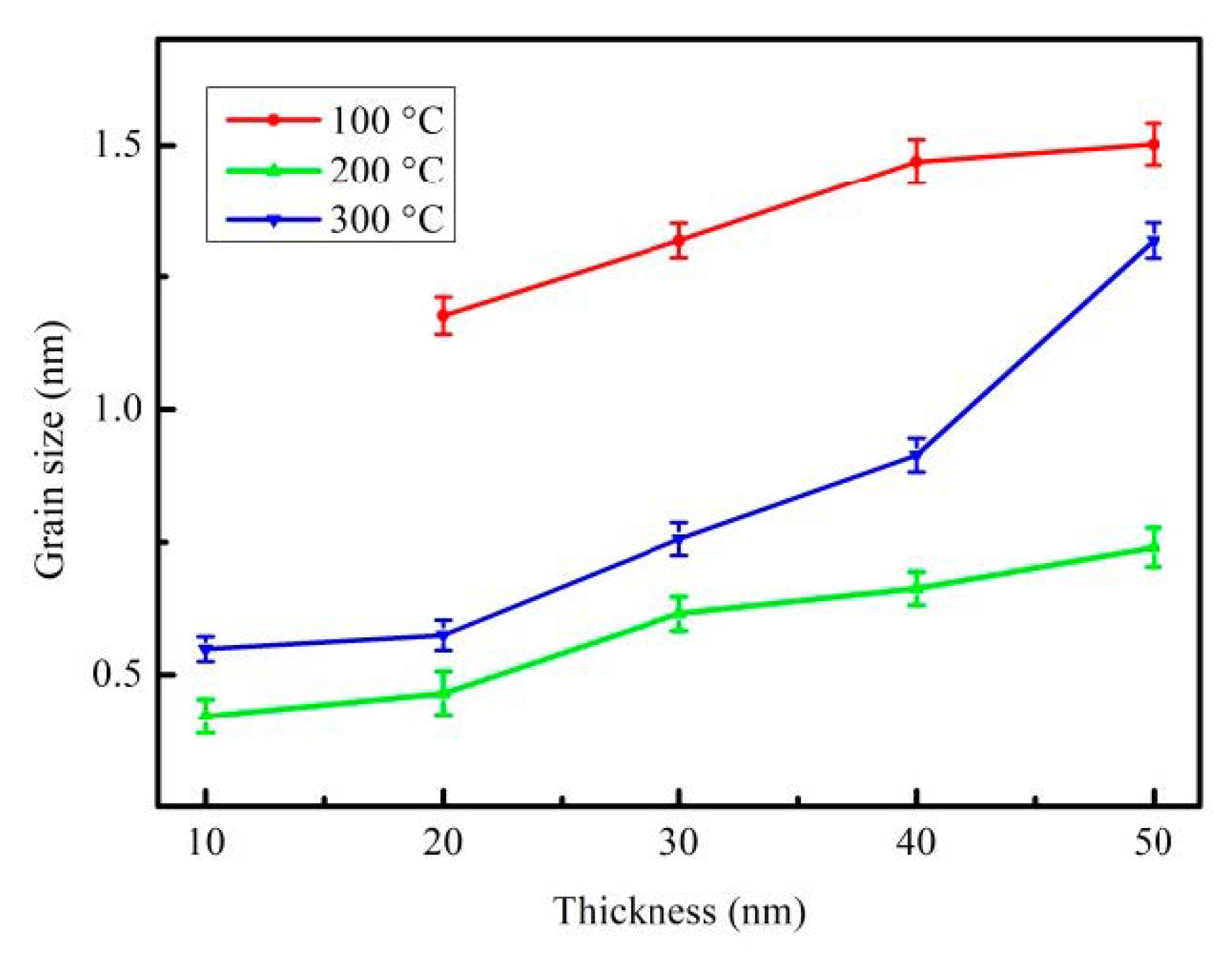
In the formula, k (0.89) denotes the Scherrer′s constant; λ represents the X-ray wavelength of the Cu Kα1 line, B is the FWHM diffraction CoFeB (110) peak and θ is the half-angle of the diffraction peak. The mean grain sizes estimated from the half maximum (FWHM, B) of the CoFeB (110) peak under four annealed conditions are plotted in Figure 2. The observed grain size, the CoFeBY thin film that had been post-annealed at 100 °C, possessed a bigger grain size, and the film that had been annealed at 200 °C possessed a smaller grain size. Furthermore, grain sizes following annealing at 200 °C and 300 °C were smaller than that post-annealed at 100 °C. This because on adding a small amount of Y to the alloy, the grains become smaller after annealing due to grain refinement [29].

3.2. Magnetic Properties

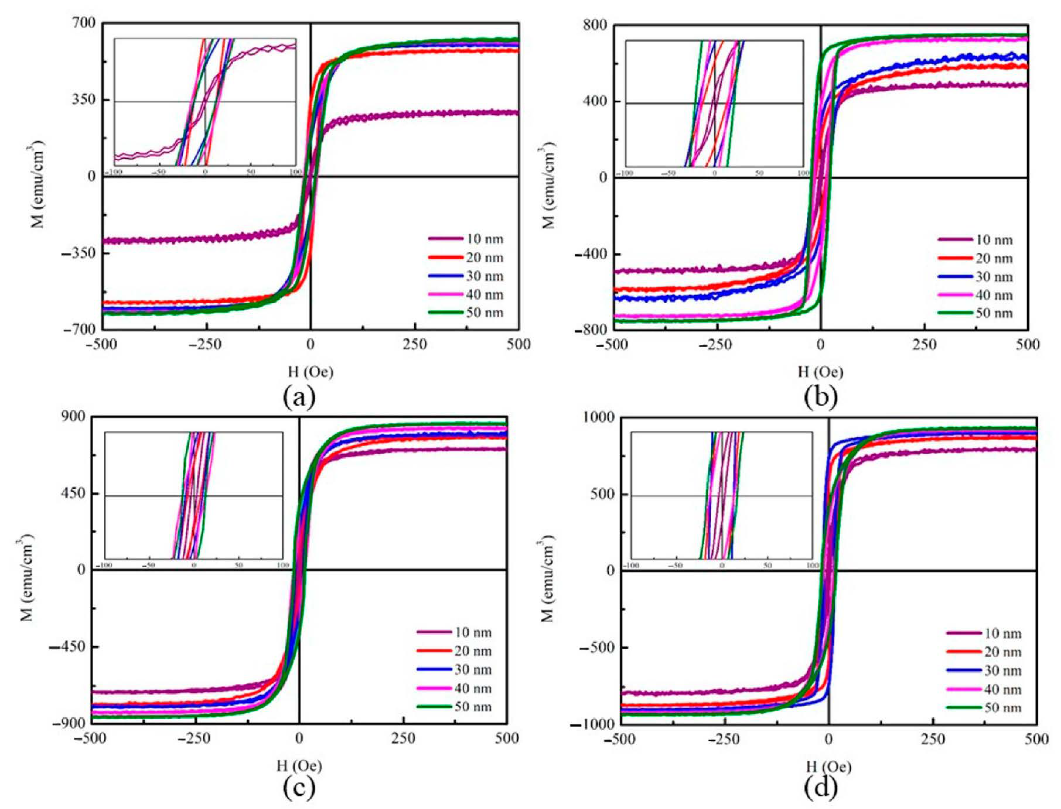
Figure 3a–d plot the in-plane magnetization hysteresis loop of CoFeBY films under the four preparation conditions according to the alternating gradient magnetometry (AGM) measurement.
The plot of the coercivity (Hc) against CoFeBY thickness is presented in the inset. The in-plane magnetic field (Hext) of 500 Oe is enough to measure the saturation magnetic spin state. It is important to mention that all samples show no transition into a transitional critical state or rotational anisotropy [30].
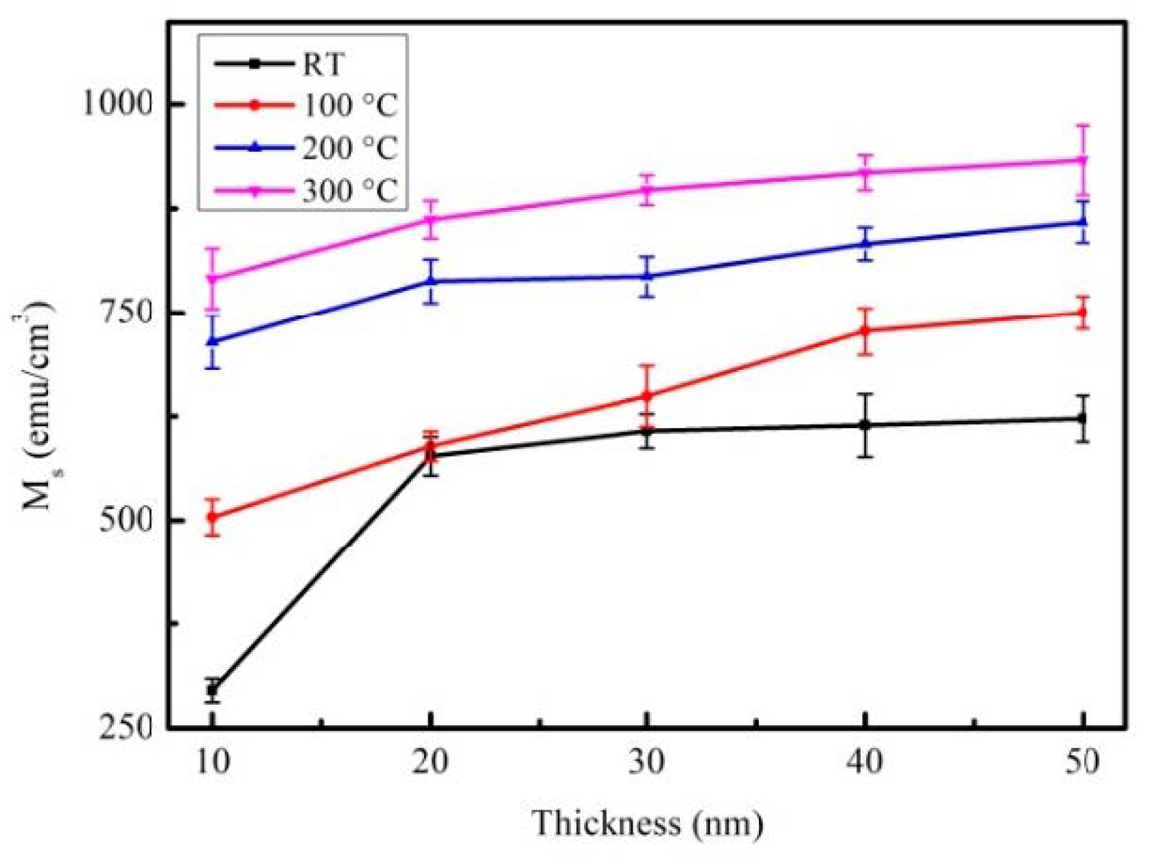
The MS of CoFeBY films is shown in Figure 4.
As the film thickness increases from 10 nm to 50 nm, Ms increases. This saturation magnetization depended on thickness, showing the thickness effect of MS in the CoFeBY film. The thin films of as-deposited and post-annealing at 100, 200, and 300 °C had MS in the range of 638 to 933 emu/cm3. However, the highest MS of CoFeBY film post-annealing was at 300 °C, indicating it has high spin coupling strength and can induce large MS. The addition of Y affects the grain refinement, improves the ferromagnetic spin exchange coupling and causes Ms to enhance the exchange coupling. Nevertheless, oxides may have significant adverse effects on amorphous properties, such as thermal and magnetic properties [31]. The introduction of Y can obtain oxygen and improve the efficiency of the alloy [32,33,34,35]. Therefore, the oxide shown in the previous XRD pattern may be the cause of the increase in magnetic properties.
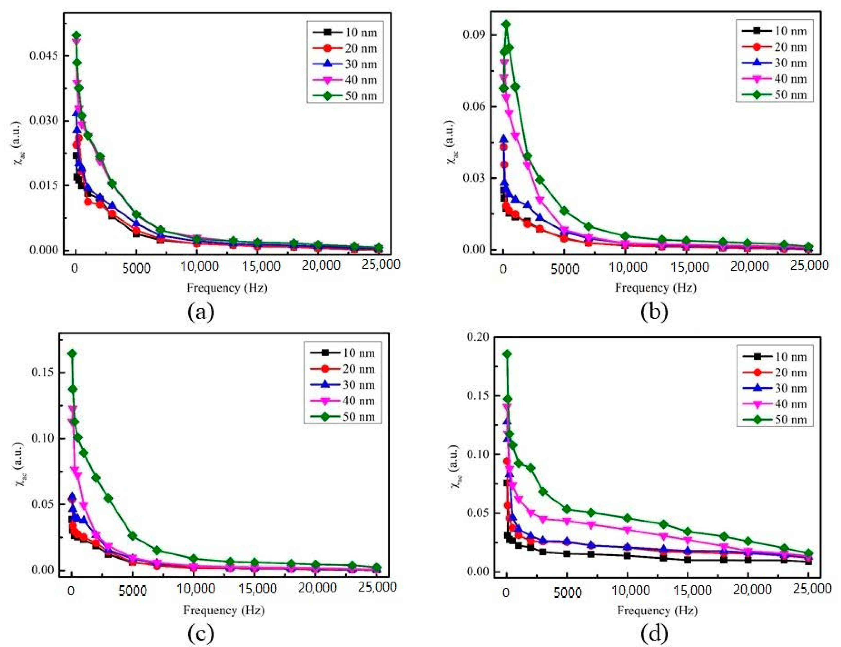
Figure 5a–d display the low-frequency alternative-current magnetic susceptibility (χac) at RT, 100, 200 and 300 °C, under four preparation conditions, with thicknesses ranging from 10 to 50 nm.
In low frequency range of 50–25,000 Hz, the value of χac decreases with the increase of frequency. The results also show that when the film thickness is between 10 nm and 50 nm, the corresponding χac value increases.
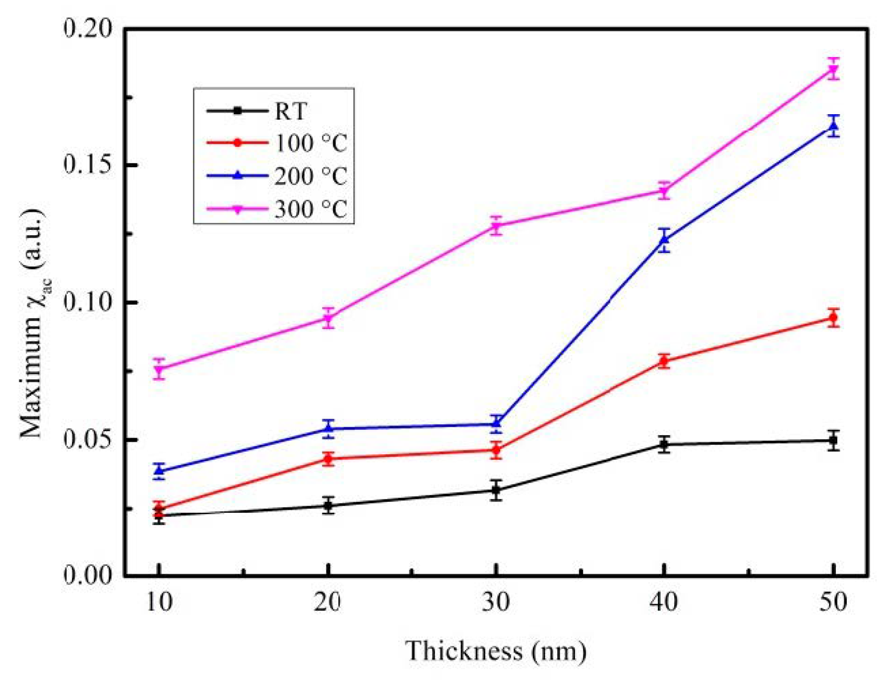
The corresponding maximum χac with various CoFeBY thicknesses under four preparation conditions are shown in Figure 6. When the maximum χac of the CoFeBY film was annealed at 300 °C, the thickness was 50 nm, which is greater than that in other conditions in this investigation. The results showed that the trend of χac was consistent with that of MS. The addition of Y can enhance the exchange coupling and affect the grain refinement, thus improving the ferromagnetic spin exchange coupling. Table 2 lists the optimal resonance frequency (fres) of CoFeBY films under four conditions. The maximum χac has the highest spin sensitivity with the optimal resonance frequency [36,37]. The fres value of CoFeBY at various thicknesses is less than 250 Hz. The optimal resonance frequency was estimated to be lower than 500 Hz, thus it can be applied in low-frequency sensors, transformers and magnetic components.

3.3. Analysis of Surface Energy and Adhesion

Table 3 depicts contact angles (θ) of the CoFeBY films at RT. The contact angles of the films were measured by using DI water and glycerol. Table 3 displays the contact angles of CoFeBY using DI water (80.8°, 80.7°, 80.1°, 80.2°, and 80.5°), and the contact angles using glycerol (79.6°, 78.0°, 77.7°, 77.4° and 79.3°). Table 4 depicts the contact angles of CoFeBY films that were post-annealed at 100 °C. The contact angles of the films were measured using DI water and glycerol. Table 4 shows the contact angles of CoFeBY using DI water (79.9°, 79.9°, 80.5°, 80.3° and 81.0°), and the contact angles using glycerol (78.1°, 78.1°, 79.7°, 79.3° and 75.1°). Table 5 depicts the contact angles of the CoFeBY films that were post-annealed at 200 °C. The contact angles of the films were detected using DI water and glycerol. Table 5 shows the contact angles of CoFeBY using DI water (78.8°, 79.3°, 78.4°, 78.6° and 78.4°), and the contact angles using glycerol (74.4°, 73.2°, 76.0°, 77.6° and 73.8°). Table 6 depicts the contact angles of the CoFeBY films that were post-annealed at 300 °C. The contact angles of the films were studied using DI water and glycerol. Table 6 shows the contact angles of CoFeBY using DI water (76.6°, 74.0°, 73.0°, 72.0° and 71.7°), and the contact angles using glycerol (75.8°, 72.7°, 73.4°, 71.9° and 71.2°).
The contact angles of the CoFeBY films under all conditions were observed to be less than 90° and the drops were nearly spherical indicating the good hydrophilicity and wettability of the films. Surface energy and adhesion are very important because CoFeBY film can be used as a seed layer or buffer layer. When the surface energy is higher, the liquid absorption is larger and the contact angle decreases. The surface energy is calculated according to the contact angle and Young’s equation [25,26,27].
Young’s Equation (2) is
σsg = σsllg cosθ
In Equation (2), σsg denotes the surface free energy of the solid, σsl represents the interfacial tension between liquid and solid, σlg is the surface tension of the liquid and θ is the contact angle.
Figure 7 shows the surface energy of CoFeBY films under all conditions, including the thickness of CoFeBY films increased from 10 nm to 50 nm at room temperature after annealing at 100, 200 and 300 °C.
It is suggested that the surface energy of post-annealed films was larger than films that were as-deposited. The surface energy ranged from 24.55 to 31.85 mJ/mm2. Due to the formation of oxide and oxide layer on the surface of CoFeBY films, the contact angle decreases and the surface energy increases when the samples are exposed to the atmosphere. When the film has a higher surface energy, the adhesion is strongest. The results indicate that it is easier to combine it the layer of the MTJ.

4. Conclusions

The structure, magnetism and adhesion of as deposited and annealed CoFeBY films were studied. XRD patterns show that the structure changes from amorphous to crystalline at annealing temperature above 100 °C. The magnetic properties show a thickness effect; as the thickness increased, the induced saturation magnetization of MS and χac increased. The addition of Y enhances the exchange coupling, improves the ferromagnetic spin exchange coupling and improves the magnetic properties. As the thickness increases from 10 nm to 50 nm, the surface energy increases. The surface energy of post-annealing film was larger than that of as-deposited film. According to the results of magnetic properties and surface energy, the optimal thickness of CoFeBY film reaches 50 nm after annealing at 300 °C. In the study, it is found that the film is suitable to be used as a free layer of MTJ and can be applied in a MRAM and recording head. The useful properties of this materials can also be estimated for sensor applications and magnetodynamic applications.

Author Contributions

Conceptualization, W.-J.L., Y.-H.C. and Y.-T.C.; Methodology, Y.-T.C., Y.-C.C., Y.-C.L.; Validation, Formal analysis, Y.-T.C. and P.-W.C.; Investigation, Y.-T.C. and W.-J.L.; Resources, T.-H.W.; Writing—original draft preparation, Y.-T.C.; Writing—review and editing, Y.-T.C. and W.-J.L.; Supervision, Y.-T.C. and Y.-H.C.; Project administration, Y.-T.C. and T.-H.W.; Funding acquisition, W.-J.L. and Y.-H.C. All authors have read and agreed to the published version of the manuscript.

Funding

This work was supported by the Ministry of Science and Technology (grant No. MOST108-2221-E-224-015-MY3 and MOST105-2112-M-224-001), and the National Yunlin University of Science and Technology (grant No. 110T06).

Institutional Review Board Statement

Not applicable.

Informed Consent Statement

Not applicable.

Data Availability Statement

The data presented in this study are available on request from the corresponding author.

Conflicts of Interest

The authors declare that there is no conflict of interests regarding the publication of this paper. The funders had no role in the design of the study; in the collection, analyses, or interpretation of data; in the writing of the manuscript, or in the decision to publish the results.

References

  1. Hayakawa, J.; Ikeda, S.; Lee, Y.; Sasaki, R.; Matsukura, F.; Meguro, T.; Takahashi, H.; Ohno, H. Current-Driven Magnetization Switching in CoFeB/MgO/CoFeB Magnetic Tunnel Junctions. Jpn. J. Appl. Phys. 2005, 44, 1267–1270. [Google Scholar] [CrossRef] [Green Version]
  2. Chen, Y.-T.; Chang, Z. Low-Frequency Alternative-Current Magnetic Susceptibility of Amorphous and Nanocrystalline Co60Fe20B20 films. J. Magn. Magn. Mater. 2012, 324, 2224–2226. [Google Scholar] [CrossRef]
  3. You, C.Y.; Ohkubo, T.; Takahashi, Y.K.; Hono, K. Boron Segregation in Crystallized MgO/Amorphous-Co40Fe40B20 Thin Films. J. Appl. Phys. 2008, 104, 033517. [Google Scholar] [CrossRef]
  4. Aoki, T.; Ando, Y.; Watanabe, D.; Oogane, M.; Miyazaki, T. Spin Transfer Switching in the Nanosecond Regime for CoFeB/MgO/CoFeB Ferromagnetic Tunnel Junctions. J. Appl. Phys. 2008, 103, 103911. [Google Scholar] [CrossRef]
  5. Seifert, T.; Jaiswal, S.; Martens, U.; Hannegan, J.; Braun, L.; Maldonado, P.; Freimuth, F.; Kronenberg, A.; Henrizi, J.; Radu, I.; et al. Efficient Metallic Spintronic Emitters of Ultrabroadband Terahertz Radiation. Nat. Photonics 2016, 10, 483–488. [Google Scholar] [CrossRef]
  6. García, D.; Muñoz, J.; Kurlyandskaya, G.; Vázquez, M.; Ali, M.; Gibbs, M. Induced Anisotropy, Magnetic Domain Structure and Magnetoimpedance Effect in CoFeB Amorphous Thin Films. J. Magn. Magn. Mater. 1999, 191, 339–344. [Google Scholar] [CrossRef]
  7. Marques, M.S.; Mori, T.J.A.; Schelp, L.F.; Chesman, C.; Bohn, F.; Correa, M.A. High Frequency Magnetic Behavior Through the Magnetoimpedance Effect in CoFeB/(Ta, Ag, Cu) Multilayered Ferromagnetic Thin Films. Thin Solid Films 2012, 520, 2173–2177. [Google Scholar] [CrossRef] [Green Version]
  8. Ikeda, S.; Miura, K.; Yamamoto, H.; Mizunuma, K.; Gan, H.D.; Endo, M.; Kanai, S.; Hayakawa, J.; Matsukura, F.; Ohno, H. A Perpendicular-Anisotropy CoFeB-MgO Magnetic Tunnel Junction. Nat. Mate. 2010, 9, 721–724. [Google Scholar] [CrossRef]
  9. You, C.Y.; Goripati, H.S.; Furubayashi, T.; Takahashi, Y.K.; Hono, K. Exchange Bias of Spin Valve Structure with a Top-Pinned Co40Fe40B20/IrMn. Appl. Phys. Lett. 2008, 93, 012501. [Google Scholar] [CrossRef]
  10. Wang, W.X.; Yang, Y.; Naganuma, H.; Ando, Y.; Yu, R.C.; Han, X.F. The Perpendicular Anisotropy of Co40Fe40B20 Sand-Wiched Between Ta and MgO Layers and its Application in CoFeB/MgO/CoFeB tunnel junction. Appl. Phys. Lett. 2011, 99, 012502. [Google Scholar] [CrossRef]
  11. Yang, Y.; Wang, W.X.; Yao, Y.; Liu, H.F.; Naganuma, H.; Sakul, T.S.; Han, X.F.; Yu, R.C. Chemical Diffusion: Another Factor Affecting the Magnetoresistance Ratio in Ta/CoFeB/MgO/CoFeB/Ta Magnetic Tunnel Junction. Appl. Phys. Lett. 2012, 101, 012406. [Google Scholar] [CrossRef]
  12. Bae, J.Y.; Lim, W.C.; Kim, H.J.; Lee, T.D.; Kim, K.W.; Kim, T.W. Compositional Change of MgO Barrier and Interface in CoFeB∕MgO∕CoFeB Tunnel Junction After Annealing. J. Appl. Phys. 2006, 99, 8. [Google Scholar] [CrossRef]
  13. Anderson, G.I.R.; Wei, H.-X.; Porter, N.A.; Harnchana, V.; Brown, A.P.; Brydson, R.M.D.; Arena, D.A.; Dvořák, J.; Han, X.-F.; Marrows, C. Changes in the Layer Roughness and Crystallography During the Annealing of CoFeB/MgO/CoFeB Magnetic Tunnel Junctions. J. Appl. Phys. 2009, 105, 063904. [Google Scholar] [CrossRef]
  14. Hayakawaa, J.; Ikeda, S.; Lee, Y.M.; Matsukura, F.; Ohno, H. Effect of High Annealing Temperature on Giant Tunnel Mag-Netoresistance Ratio of CoFeB/MgO/CoFeB Magnetic Tunnel Junctions. Appl. Phys. Lett. 2006, 89, 232510. [Google Scholar] [CrossRef] [Green Version]
  15. Liu, J.; Wu, Q.; Yan, H.; Zhong, S.; Huang, Z. Effect of Trace Yttrium Addition and Heat Treatmenton the Microstructure and Mechanical Properties of As-Cast ADC12 Aluminum Alloy. Appl. Sci. 2019, 9, 53. [Google Scholar] [CrossRef] [Green Version]
  16. Baulin, O.; Bugnet, M.; Fabrègue, D.; Lenain, A.; Gravier, S.; Cazottes, S.; Kapelski, G.; Ovanessian, B.T.; Balvay, S.; Hartmann, D.J.; et al. Improvement of Mechanical, Thermal, and Corrosion Properties of Ni- and Al-free Cu–Zr–Ti Metallic Glass with Yttrium Addition. Materialia 2018, 1, 249–257. [Google Scholar] [CrossRef]
  17. Liu, Z.; Qian, D.; Zhao, L.; Zheng, Z.; Gao, X.; Ramanujan, R. Enhancing the Coercivity, Thermal Stability and Exchange Coupling of Nano-Composite (Nd,Dy,Y)–Fe–B alloys with reduced Dy content by Zr addition. J. Alloys Compd. 2014, 606, 44–49. [Google Scholar] [CrossRef]
  18. Gu, Z.; Ma, D.; Xu, C.; Liu, T.; Cheng, L.; Du, Y.; Zhang, W. Crystal Structure and Phase Relations of the R2Fe14B–Y2Fe14B (R = Nd and Pr) Systems. J. Supercond. Nov. Magn. 2017, 31, 271–278. [Google Scholar] [CrossRef]
  19. Ahmad, Z.; Yan, M.; Liu, Z.W.; Tao, S.; Ma, T. High coercivity (Nd8Y3)–(Fe62Nb3Cr)–B23 Magnets Produced by Injection Casting. J. Mater. Sci. 2013, 48, 1779–1786. [Google Scholar] [CrossRef]
  20. Yoshizawa, Y.; Oguma, S.; Yamauchi, K. New Fe-Based Soft Magnetic Alloys Composed of Ultrafine Grain Structure. J. Appl. Phys. 1988, 64, 6044–6046. [Google Scholar] [CrossRef]
  21. Herzer, G. Soft Magnetic Nanocrystalline Materials. Scr. Met. Mater. 1995, 33, 1741–1756. [Google Scholar] [CrossRef]
  22. Makino, A.; Hatanai, T.; Naitoh, Y.; Bitoh, T.; Inoue, A.; Masumoto, T. ChemInform Abstract: Applications of Nanocrystalline Soft Magnetic Fe-M-B (M: Zr, Nb) Alloys “NANOPER”. Chemistry 2010, 29, 3793–3798. [Google Scholar] [CrossRef]
  23. Liu, W.-J.; Ou, S.-L.; Chang, Y.-H.; Chen, Y.-T.; Wang, Y.-T.; Liang, Y.-C.; Tseng, J.-Y.; Chi, P.-W. Magnetic Susceptibility, Optical, and Adhesive Properties of Co40Fe40V10B10 films. Surf. Eng. 2020, 36, 405–410. [Google Scholar] [CrossRef]
  24. Ou, S.-L.; Liu, W.-J.; Chang, Y.-H.; Chen, Y.-T.; Wang, Y.-T.; Li, W.-H.; Tseng, J.-Y.; Wu, T.-H.; Chi, P.-W.; Chu, C.-L. Structure, Magnetic Property, Surface Morphology, and Surface Energy of Co40Fe40V10B10 Films on Si(100) Substrate. Appl. Sci. 2020, 10, 449. [Google Scholar] [CrossRef] [Green Version]
  25. Ma, K.; Chung, T.S.; Good, R.J. Surface Energy of Thermotropic Liquid Crystalline Polyesters and Polyesteramide. J. Polym. Sci. 1998, 36, 2327–2337. [Google Scholar] [CrossRef]
  26. Owens, D.K.; Wendt, R.C. Estimation of the Surface Free Energy of Polymers. J. Appl. Polym. Sci. 1969, 13, 1741–1747. [Google Scholar] [CrossRef]
  27. Kaelble, D.H.; Uy, K.C. A Reinterpretation of Organic Liquid-Polytetrafluoroethylene Surface Interactions. J. Adhes. 1970, 2, 50–60. [Google Scholar] [CrossRef]
  28. Cullity, B.D.; Weymouth, J.W. Elements of X-Ray Diffraction. Am. J. Phys. 1957, 25, 394–395. [Google Scholar] [CrossRef] [Green Version]
  29. Zhang, C.H.; Luo, Y.; Yu, D.B.; Quan, N.T.; Wu, G.Y.; Dou, Y.K.; Hu, Z.; Wang, Z.L. Permanent Magnetic Properties of Nd–Fe–B Melt-Spun Ribbons with Y Substitution. Rare Metals 2020, 39, 55–61. [Google Scholar] [CrossRef]
  30. Svalov, A.; Bespalko, O. Rotational Magnetic Anisotropy in Amorphous Gd-Co films. J. Magn. Magn. Mater. 1995, 148, 134–135. [Google Scholar] [CrossRef]
  31. Chen, Y.-T.; Xie, S.M. Magnetic and Electric Properties of Amorphous Co40Fe40B20Thin Films. J. Nanomater. 2012, 2012, 1–5. [Google Scholar] [CrossRef] [Green Version]
  32. Lu, Z.P.; Liu, C.T.; Porter, W.D. Role of Yttrium in Glass Formation of Fe-Based Bulk Metallic Glasses. Appl. Phys. Lett. 2003, 83, 2581–2583. [Google Scholar] [CrossRef]
  33. Yan, M.; Shen, J.; Zhang, T.; Zou, J. Enhanced Glass-Forming Ability of a Zr-Based Bulk Metallic Glass with Yttrium Doping. J. Non-Cryst. Solids 2006, 352, 3109–3112. [Google Scholar] [CrossRef]
  34. Zhang, Y.; Pan, M.X.; Zhao, D.Q.; Wang, R.J.; Wang, W.H. Formation of Zr-Based Bulk Metallic Glasses from Low Purity of Materials by Yttrium Addition. Mater. Trans. JIM 2000, 41, 1410–1414. [Google Scholar] [CrossRef] [Green Version]
  35. Eckert, J.; Mattern, N.; Zinkevitch, M.; Seidel, M. Crystallization Behavior and Phase Formation in Zr–Al–Cu–Ni Metallic Glass Containing Oxygen. Mater. Trans. JIM 1998, 39, 623–632. [Google Scholar] [CrossRef] [Green Version]
  36. Chen, Y.T.; Xie, S.M.; Jheng, H.Y. The Low-Frequency Alternative-Current Magnetic Susceptibility and Electrical Properties of Si(100)/Fe40Pd40B20(X Å)/ZnO(500 Å) and Si(100)/ZnO(500 Å)/Fe40Pd40B20 (Y Å) systems. J. Appl. Phys. 2013, 113, 17B303. [Google Scholar] [CrossRef]
  37. Kong, S.H.; Okamoto, T.; Nakagawa, S. [Ni-Fe/Si] Double Seedlayer with Low Surface Energy for Fe-Co-B Soft Magnetic Underlayer with high Hk for Perpendicular Magnetic Recording Media. IEEE Trans. Magn. 2004, 40, 2389–2391. [Google Scholar] [CrossRef]
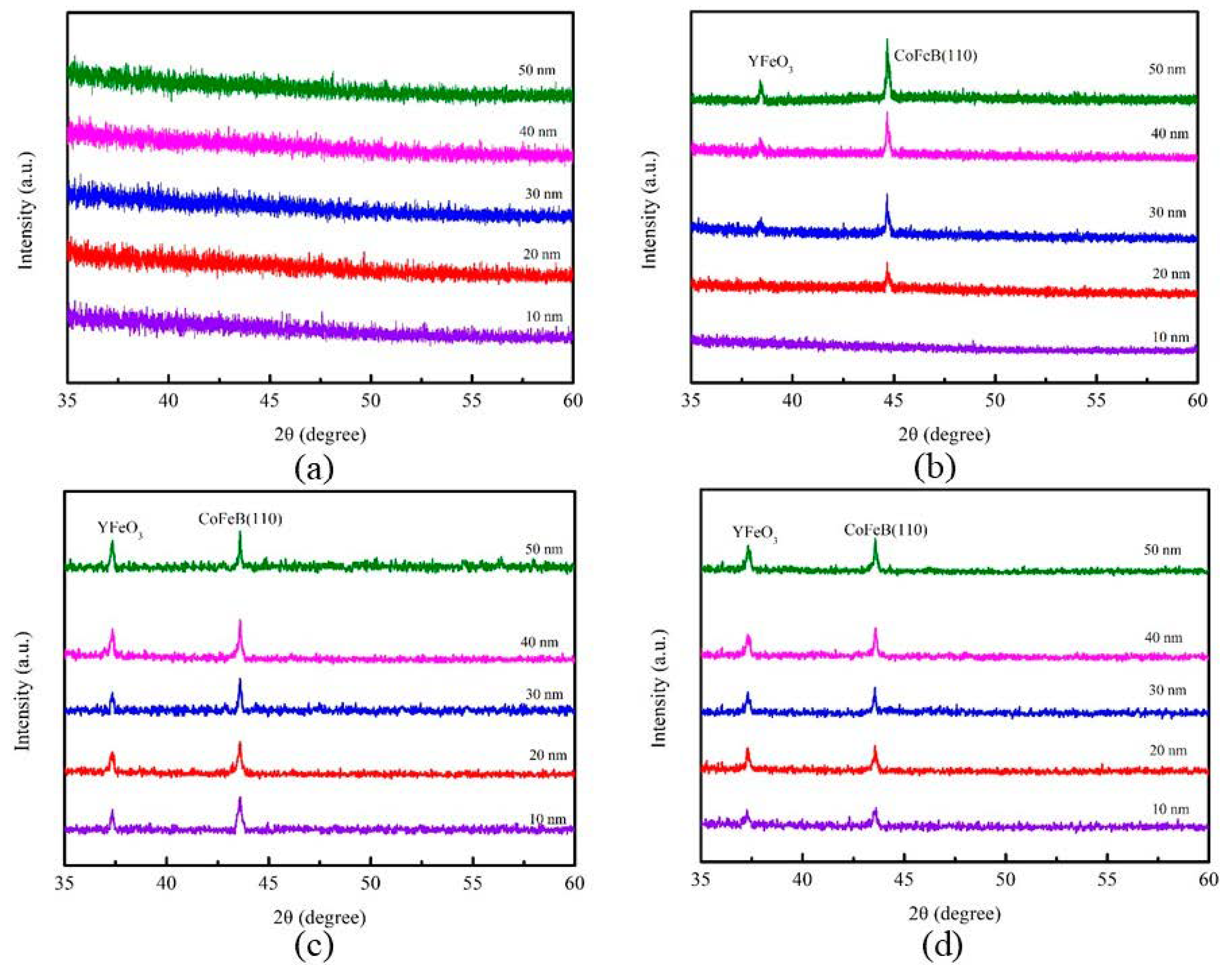
Figure 1. X-ray diffraction (XRD) patterns of CoFeBY films. (a) room temperature (RT), (b) after annealing at 100 °C, (c) after annealing at 200 °C, (d) after annealing at 300 °C.
Materials 14 00987 g001
Figure 2. The mean grain size distribution of CoFeBY films.
Materials 14 00987 g002
Figure 3. In-plane magnetic hysteresis loop of CoFeBY films. (a) RT, (b) after annealing at 100 °C, (c) after annealing at 200 °C, (d) after annealing at 300 °C.
Materials 14 00987 g003
Figure 4. Saturation magnetization (MS) of CoFeBY thin films.
Materials 14 00987 g004
Figure 5. The low-frequency alternate-current magnetic susceptibility (χac) as a function of the frequency from 50 to 25,000 Hz. (a) RT, (b) after annealing at 100 °C, (c) after annealing at 200 °C, (d) after annealing at 300 °C.
Materials 14 00987 g005
Figure 6. Maximum alternate-current magnetic susceptibility for the CoFeBY films.
Materials 14 00987 g006
Figure 7. Surface energy of CoFeBY thin films.
Materials 14 00987 g007
Table 1. Specific properties for various Glass/CoFeVB, Si (100)/CoFeVB, and Si (100)/CoFeBY materials.
MaterialThickness (nm)Maximum χac
(a.u.)
Optimal Resonance
Frequency, fres (Hz)
Surface Energy
(mJ/mm2)
Glass/Co40Fe40V10B10 [23]10–40 at RT0.068–0.09850–100065.5–38
Si (100)/Co40Fe40V10B10 [24]10–40 at RT0.013–0.01950–20034.2–51.5
Si (100)/Co40Fe40B10Y1010–50 at RT and
annealed conditions
0.022–0.18550–25024.6–31.9
Table 2. Optimal resonance frequency for films of various thicknesses.
ThicknessRTAfter Annealing at 100 °CAfter Annealing at 200 °CAfter Annealing at 300 °C
10 nm50505050
20 nm250505050
30 nm50505050
40 nm5010010050
50 nm502505050
Table 3. Average contact angles of CoFeBY thin films at RT with DI water and glycerol.
Co40Fe40B10Y10 (10–50 nm)Contact Angle(θ) with DI Water
as Test Liquid
Contact Angle(θ) with Glycerol as Test Liquid
10 nm80.8°79.6°
20 nm80.7°78.0°
30 nm80.1°77.7°
40 nm80.2°77.4°
50 nm80.5°79.3°
Table 4. Average contact angles of CoFeBY thin films after annealing at 100 °C with DI water and glycerol.
Co40Fe40B10Y10 (10–50 nm)Contact Angle(θ) with DI Water
as Test Liquid
Contact Angle(θ) with Glycerol as Test Liquid
10 nm79.9°78.1°
20 nm79.9°78.1°
30 nm80.5°79.7°
40 nm80.3°79.3°
50 nm81.0°75.1°
Table 5. Average contact angles of CoFeBY thin films after annealing at 200 °C with DI water and glycerol.
Co40Fe40B10Y10 (10–50 nm)Contact Angle(θ) with DI Water
as Test Liquid
Contact Angle(θ) with Glycerol as Test Liquid
10 nm78.8°74.4°
20 nm79.3°73.2°
30 nm78.4°76.0°
40 nm78.6°77.6°
50 nm78.4°73.8°
Table 6. Average contact angles of CoFeBY thin films after annealing at 300 °C with DI water and glycerol.
Co40Fe40B10Y10 (10–50 nm)Contact Angle(θ) with DI Water
as Test Liquid
Contact Angle(θ) with Glycerol as Test Liquid
10 nm76.6°75.8°
20 nm74.0°72.7°
30 nm73.4°73.0°
40 nm72.0°71.9°
50 nm71.7°71.2°
Publisher’s Note: MDPI stays neutral with regard to jurisdictional claims in published maps and institutional affiliations.