Abstract
Graphite/Al composites had attracted significant attention for thermal management applications due to their excellent thermal properties. However, the improvement of thermal properties was restricted by the insufficient wettability between graphite and Al. In this study, silicon carbide and titanium carbide coatings have been uniformly coated on the graphite by the reactive sputtering method, and Graphite/Al laminate composites were fabricated by a hot isostatic pressing process to investigate the influence on thermal conductivity and mechanical properties. The results show that carbide coating can effectively improve the interfacial thermal conductance of SiC@Graphite/Al and TiC@Graphite/Al composites by 9.8 times and 3.4 times, respectively. After surface modification, the in-plane thermal conductivity (TC) of the composites with different volume fractions are all exceeding the 90% of the predictions. In comparison, SiC is more conducive to improving the thermal conductivity of composite materials, since the thermal conductivity of the 28.7 vol.% SiC@Graphite/Al reached the highest value of 499 W/m·K, while TiC is favorable for improving the mechanical properties. The finding is beneficial to the understanding of carbide coating engineering in the Graphite/Al composites.
1. Introduction
With the rapid development of electronic devices, vast quantities of heat caused by integration and miniaturization have become the issue to restrict their reliability and lifetime. Therefore, thermal management materials, such as heat dissipation substrate and heat sink, should have high thermal conductivity (TC), a certain mechanical strength and low thermal expansion coefficient matching with substrate, so as to ensure the thermal stability and avoid device failure due to insufficient heat output [1,2,3]. Nevertheless, some traditional thermal management materials, such as Cu/Mo and Cu/W, could no longer fulfill the requirements for high-power electronic devices [4,5]. Thus, metal matrix composites (MMCs) reinforced with high TC carbon materials, such as carbon fibers [6], graphite, diamond [7], carbon nanotubes [8] and graphene [9], have gradually come into view.
To date, some works have been done as a result of combine graphite with metal composite through different processes. Prieto et al. [10] obtained the graphite flake (Gf)-reinforced composite by infiltrating Al into the preform, which had TC between 294 and 390 W/m·K. Zhou et al. [11] introduced a small percentage of Si particles as spacers between the layers Gf so that metal could be more easily to infiltrated in, which had TC in the range of 179–526 W/m·K. Li et al. [12] manufactured 70 vol.% Gf/Al composites with preferred orientation, and the TC reached to 714 W/m·K. Up until now, existing research still has a big gap in the theoretical value of TC. It is also known that additional amounts of graphite will inevitably lead to a decline in mechanical properties; therefore, it is essential to achieve high TC with a relative low reinforcement volume, so that the composite can still retain good mechanical properties. In addition, the TC of graphite in (002) crystal plane can reach 2200 W/m·K at room temperature [13]. Strong anisotropy on TC means the control of the distribution and orientation of the reinforcements is also a problem, especially for the micron-scaled graphite flake. Based on this, Huang et al. [14,15] used graphite films and aluminum foils as raw materials and fabricated the laminate composites by vacuum hot pressing, successfully solving the problem on orientation: the TC of their obtained composites could reach as high as 902 W/m·K.
Another major problem restricting the TC is the poor wettability of graphite and aluminum, and harmful reaction may occur on the interface. Thus, the strong carbide-forming elements were introduced in order to improve the interfacial bonding strength and hinder the interfacial reaction [16,17].
In this work, two different carbide coatings (SiC/TiC) were applied to the surface of graphite film by reactive sputtering. Then, graphite film and aluminum were fabricated into laminate composites by hot isostatic pressing (HIP), aimed at elucidating the interfacial structure between different carbide coating and Al and to clarify the key factors influencing the TC and mechanical properties of the composites.
2. Materials and Methods
2.1. Raw Materials
Graphite films and 1060 Al foils (99.6% in purity, with TC of 234 W/m·K) were used as raw materials. Al foils with thickness of 50 μm and 25 μm were purchased from Shanghai Yuanyi Metals Co. Ltd (Shanghai, China) the graphite films with average thickness of 25 μm were acquired from Qingdao Kangboer Graphite Co., Ltd. (Qingdao, China).
Figure 1 shows the morphology and X-ray diffraction (XRD) pattern of the graphite film. The characteristic diffraction peak is (002) peak and (004) peak, in which the graphite’s full width at half maximum (FWHM) and the distance of (002) crystal face can be acquired. The graphitization degree can be calculated by the Mering and Maire formula:
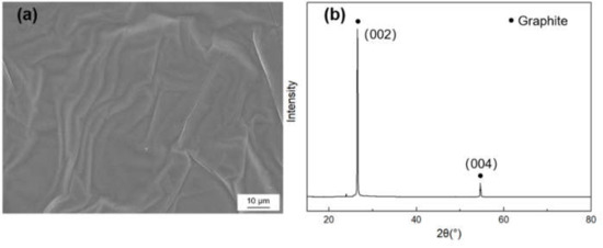
Figure 1.
(a) SEM morphology and (b) X-ray diffraction (XRD) pattern of the graphite film.
Here, is the graphitization degree, d002 is the average layer spacing of crystal face, the layer spacing of the ideal graphite crystal is 0.3354 nm and the layer spacing of amorphous carbon is 0.344 nm. The crystallite parameters of graphite film are listed in Table 1, and the in-plane and axial TC of the graphite films were measured to be 1189 W/m·K and 18 W/m·K, respectively.

Table 1.
Crystallite parameter of graphite film.
2.2. Carbide Coating on the Graphite
Graphite films were washed by Ar ions for 20 min to eliminate impurities on the surface. Titanium (purity 99.995%) and silicon (purity 99.99%) were used as the target and controlled by radio frequency cathode. When the background pressure was lower than 3 × 10⁻⁴ Pa, a mixture of argon and acetylene was introduced into the vacuum chamber, and the total pressure of the mixed gas was kept at 0.5 Pa. In order to improve the adhesion between the film and graphite, a thin titanium (silicon) layer was predeposited on the graphite before reactive sputtering. It was necessary to keep the thickness of carbide coating within 200 nm, due to its low TC. The thickness of the coating layer was controlled by the deposition time.
2.3. Preparation of Graphite/Al Composites
The coated graphite films and Al foils were cut into the designed size and subsequently layered into laminate material and heated in a HIP furnace. The volume fractions of graphite were obtained by controlling the thickness of the aluminum foils (11.1%, 18.9% 28.7%). The furnace was heated up to 585 °C by 10 °C/min and held for 120 min in 120 MPa.
2.4. Characterization
X-ray diffraction (,XRD-6000, Shimadzu, Kyoto, Japan) was applied to investigate the phase of graphite and composite, and a high resolution transmission electron microscope (TEM, Jem-2100, Jeol, Tokyo, Japan) was used to detect the crystal structure of the films. The microstructure was observed by an optical microscope (OM, Axiovert A1, Zeiss, Oberkochen, Germany) and a field emission scanning electron microscope (FE-SEM, JSM-7600F, Jeol, Tokyo, Japan). Energy dispersion spectra (EDS) attached to the FE-SEM was applied to determine and analyze the elemental composition and distribution. The TC of composite was calculated by the following formula:
Here, is the thermal diffusion coefficient of the composite measured at room temperature by a laser flash thermal analyzer (LFA-447, Netzsch, Selb, Germany), is density of the composite measured by Archimedes principle, is specific heat of the composite, which was calculated according to rule of mixture:
, is the specific heat and , is the volume fraction of aluminum and graphite, respectively.
3. Results and Discussion
3.1. Microstructures Characterization of the Coated Graphite
The surface morphology and energy dispersion spectra (EDS) mapping result of Ti-coated graphite are illustrated in Figure 2. The coating surface was integrated and homogenous, and it can be seen from the EDS mapping results that Ti elements were evenly dispersed on the graphite. The XRD pattern shows a sharp peak at 2θ = 54.1°, corresponding to the (004) crystal of graphite and four weak diffraction peaks at 2θ = 35.9°, 41.8°, 60.5° and 76.4°, corresponding to the (111), (200), (220) and (222) crystal planes of TiC, which indicates that the TiC coating has successfully formed on the graphite.
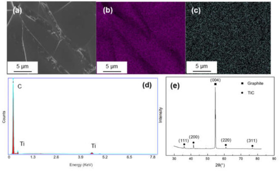
Figure 2.
(a) SEM morphology and of Ti-coated graphite; (b,c) EDS mapping results of C and Ti; (d,e) EDS spectrum and XRD pattern of the Ti-coated graphite.
Figure 3 shows the SEM morphology and EDS mapping result of Si-coated graphite. It can be seen from Figure 3c that there is no obvious segregation of silicon on graphite. The EDS spectrum shows only Si and C signals. In the XRD pattern, there are three diffraction peaks at 2θ = 35.7°, 43.2° and 60.2°, corresponding to the (102), (103) and (110) crystal planes of SiC.
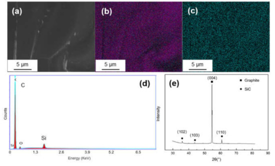
Figure 3.
(a) SEM morphology and of Ti-coated graphite; (b,c) EDS mapping results of C and Si; (d,e) EDS spectrum and XRD pattern of the Si-coated graphite.
3.2. Microstructure Characterization of Ti-Coated Graphite/Al Composites
The coated graphite and Al foils was fabricated into Graphite/Al composite, and the TEM samples containing the interface were prepared by focused ion beam (FIB). As shown in Figure 4a, continuous and uniform coating can be observed at the section, and the thickness of the coating was measured to be 183 nm. In order to further determine the phase and lattice orientation of the interface, the sample was observed by high resolution transmission electron microscope (HRTEM), and fast Fourier transform (FFT) was carried out to analyze the nanostructure with a digital micrograph. It can be noted from Figure 4b that the coating layer consisted of two different regions, including a thin, predeposited titanium layer with thickness of 15–20 nm; the rest of the area could be identified as a cubic structured TiC layer. In addition, nano-scaled TiC particles could be observed in partial interface areas between Ti and graphite (as shown in Figure 5). We speculated that TiC may be produced by the interfacial reaction under high temperature and high pressure, and the interface combination was enhanced to a certain extent.
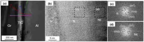
Figure 4.
(a) Interface morphology of the Ti-coated Graphite/Al prepared by focused ion beam (FIB); (b) high resolution transmission electron microscope (HRTEM) image of Ti-coated graphite surface; (c,d) fast Fourier transform (FFT) of (b).
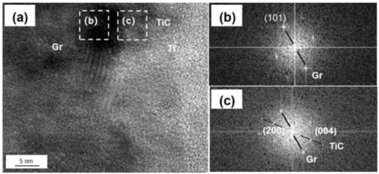
Figure 5.
(a) HRTEM image of Ti-graphite surface; (b,c) FFT of (a).
Figure 6a shows the HRTEM image of interfacial microstructure between TiC and Al, and the same lattice direction between (111)TiC (0.242 nm) and (111)Al (0.236 nm) can be observed. The transmission electron beam is parallel to the crystallographic orientation of [11]TiC and [11]Al, respectively. The lattice mismatch can be calculated by the formula:
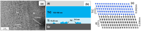
Figure 6.
(a) HRTEM image of the TiC/Al interface; (b) Schematic drawing of interfacial structure of the Graphite/Al (Ti) composites; (c) Schematic diagram of the TiC/Al interfacial structure.
The mismatch between (111)TiC and (111)Al is 3.2%. Small mismatch means a good bonding strength between Al and Ti-coated graphite.
3.3. Microstructure Characterization of Si-Coated Graphite/Al Composites
Figure 7 shows the interfacial structure of the Si-coated Graphite/Al composites. The thickness of the coating layer was measured to be 167 nm. Al and SiC, with face-centered cubic structure, could be observed in the HRTEM image, and the interface between Al and the coating layer was very clear. From the FTT image, we can infer that the transmission electron beam is parallel to the direction of [110]Al and [200]SiC, respectively. The crystal plane spacing between Al and SiC is quite different; thus, the (110)Al does not grow along the (110)SiC, and a parallel lattice direction between (110)SiC (0.185 nm) and (1)Al (0.204 nm) could be recognized. Additionally, unreacted hexagonal silicon particles were observed in the coating layer (as shown in Figure 8). The mismatch between (110)SiC and (1)Al is 11.8%, which is equivalent to seven Al atomic lattice corresponding to eight SiC atomic lattice. This is because the space lattice of Al and SiC cannot match completely, and the bond energy of Al is larger than that of SiC. The formation of vacancy is beneficial to reduce the free energy of the interface and obtain a relatively stable interface bonding.
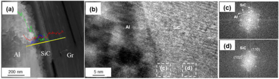
Figure 7.
(a) Interface morphology of the Si-coated Graphite/Al prepared by FIB; (b) HRTEM image of SiC/Al surface; (c,d) FFT of (b).
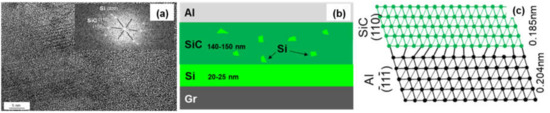
Figure 8.
(a) HRTEM image of the SiC/Al interface; (b) Schematic drawing of interfacial structure of the Graphite/Al (Si) composites; (c) Schematic diagram of the SiC/Al interfacial structure.
3.4. Thermal and Mechanical Properties
In order to study the effect of graphite with different coatings (TiC, SiC, uncoated) on TC, the composites with different graphite volume fraction (11.1–28.7%) were fabricated by HIP. Figure 9 shows that the composites have an expected layered structure, and the graphite film and Al layer are arranged alternately. The orientation of graphite film was well-controlled, which is basically along the in-plane direction of the composite. The interface between graphite film and Al matrix was well-bonded, and there are no obvious holes and defects. This makes the orientation degree of the graphite film much better than that of the Graphite flake/Al composite, and this structure can give full play to the strengthening effect of high TC graphite film.
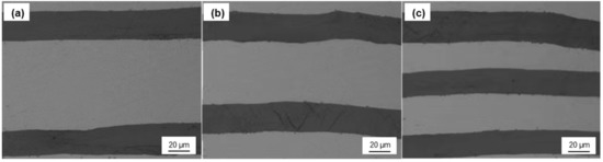
Figure 9.
Optical microphotograph of the composite with different graphite volume fraction: (a) 11.1%; (b) 19.8%; (c) 28.7%.
Figure 10 depicts the in-plane and out-of-plane TC of Graphite film/Al composites with different graphite volume fraction; the TC predictions of laminate composites were given by [18]:
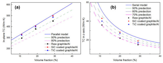
Figure 10.
Comparison of the experimental TC of the composites to the predictions by TC model of laminate composites: (a) in-plane direction; (b) out-of-plane direction.
In-plane direction:
Out-of-plane direction:
Here, represents the volume fraction of graphite ands K, and represent the TC of composite, graphite film and Al, respectively.
It can be seen from Figure 10 that the carbide coating and increasing the volume fraction of graphite will both increase the TC of composites. After surface modification, the in-plane TC values of the composites with different volume fractions are all exceeding the 90% of the predictions, which could be due to the strong interfacial bonding and well-controlled orientation of graphite films. With increasing volume fraction of SiC-coated graphite from 11.1 to 28.7%, the in-plane TC increases from 330 to 499 W/m·K. As for TiC-coated graphite, the in-plane TC increases from 323 to 486 W/m·K. Compared with the composite reinforced by uncoated graphite, the TC of the composite is increased by 10.2% and 7.5% respectively. However, the TC in the z-axis shows a downward trend as the volume fraction of graphite increases. When the composite was reinforced by uncoated graphite, the TC was only 70% of the predictions, while this value can reach about 80% after carbide coating. This phenomenon can be attributed to the following reasons: the TC of graphite in the vertical direction is much lower than that in the plane direction, and the heat flow will be preferentially conducted in the direction of high TC, resulting in adverse effects on the vertical TC. In addition, when the heat flows along the vertical direction, it will pass through many interfaces; therefore, the TC is very sensitive to interfacial status, especially for the defects that may form in composites. To summarize, after the interface modification, the TC of the composites in the plane direction is very close to the theoretical value, which indicates that the carbide coating plays a positive role in improving the TC.
The heat conduction mode of graphite is phonon conduction, but the effect of phonon conduction in Al is very poor. The addition of carbide coating helps to alleviate the difference of phonon conduction between graphite and Al. Therefore, it is necessary to further study the effect of different carbide coating on the interfacial thermal conductance (ITC) of the composite. The TC in the out-of-plane direction was selected as the research object in order to consider the effect of carbide coating. It can be solved by replacing the measured TC value with an effective TC, including the effect of ITC,, which was given by [19]:
Here, the intrinsic TC of graphite, h is the ITC and D is the diameter of the inclusion. Thus, the actual ITC can be calculated by Equation (6), while the theoretical ITC could be estimated by the acoustic mismatch model (AMM) [20]:
where , c and v are the mass density, the specific heat capacity and the phonon velocity, respectively. The subscripts c and m refer to the graphite and metal matrix, respectively. The relevant parameters of the materials used for the calculation are tabulated in Table 2.
Table 2.
Parameters of materials for the acoustic mismatch model (AMM) model.
The theoretical ITC between graphite and Al was calculated to be 4.3 × 10⁷ W/m2 K. The carbide coating can act as the intermediate layer for phonon propagation, which forms an effective phonon velocity gradient at the interface of the composite, so that the phonon scattering at the interface can be suppressed. After introducing carbide coating, the theoretical ITC of SiC-coated graphite and TiC-coated graphite was increased to 6.7 × 10⁷ W/m2 K and 5.5 × 10⁷ W/m2 K, respectively.
As shown in Figure 11, the actual ITC calculated by Equation (6) is in the same order of magnitude as the theoretical value. In this study, the thickness of the coating layer is very thin, so the theoretical ITC values of TiC and SiC are very close. However, it should be noted that, due to the low TC of TiC, the ITC will decrease with the increase of thickness. From the calculated value of the experiment, there is still a certain gap between the experimental value and the theoretical value, especially for the uncoated graphite, which may be due to the interface defects caused by the poor wettability between aluminum and graphite. Through the surface modification, the ITC of the composites has been improved, correspondingly, but the interface reaction between TiC coating and graphite may aggravate the phonon scattering at the interface, so the improvement of ITC is relatively constrained. Compared with TiC coating, the interface of SiC is relatively pure and firmly bonded with the graphite and metal matrix, which can more effectively improve the ITC.
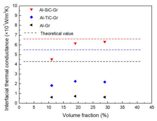
Figure 11.
Comparison of interfacial thermal conductance to different composites.
The mechanical properties of composites with different volume fractions of graphite are listed in Table 3. Obviously, the tensile strength sharply decreases with the increasing of the volume fraction of graphite, and the mechanical properties of the composites become very sensitive to the interface bonding when the volume fraction of graphite is high. The experimental measurements for coated Graphite/Al composites show higher values than that of the raw Graphite/Al composites. As is shown in Figure 12, owing to the weak bonding between raw graphite and metal matrix, the graphite was completely disengaged and pulled out from matrix. For 28.7 vol.% raw Graphite/Al composite, the tensile strength is 33 MPa. When the graphite is coated with SiC or TiC, the tensile strength increased to 39 MPa and 44 MPa, respectively. Additionally, the fracture of composite reinforced by coated graphite is very even, and the graphite remains bonded with matrix. Compared with SiC coating, TiC-coated graphite has higher mechanical properties, which may be due to the lower crystal plane mismatch between TiC and matrix and the interface reaction with graphite, which both improve the mechanical properties.
Table 3.
Mechanical properties of composites with different volume fractions of graphite.
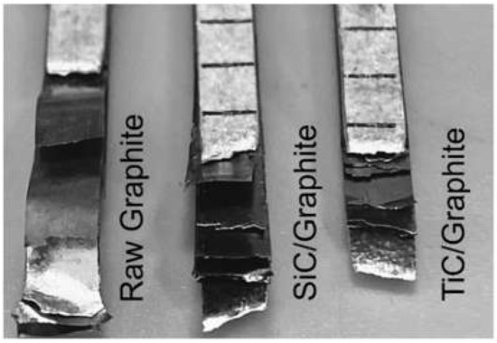
Figure 12.
Tensile fracture morphology of composites.
4. Conclusions
The carbide-coated graphite and the interface of the Graphite/Al composites were systematically studied to reveal their influence on thermal and mechanical properties. By controlling the deposition interfacial structure, continuous and uniform carbide coating with thickness less than 200 nm was successfully deposited on the graphite surface. The nanometer-scale carbide coating improved the bonding between graphite and Al, the phonon scattering at the interface was reduced accordingly and the ITC of SiC@Graphite/Al and TiC@Graphite/Al composites were increased by 9.8 times and 3.4 times, respectively. After surface modification, the in-plane TC of the composites with different volume fractions were all exceeding the 90% of the predictions, with increasing volume fraction of graphite from 11.1 to 28.7%. The TC of SiC@Graphite/Al composites increased from 330 to 499 W/m·K; for TiC@Graphite/Al composites, the TC increased from 323 to 486 W/m·K, which was 10.4% and 7.5% higher compared to that of the Graphite/Al, respectively. In addition, the mechanical properties of the composites reinforced by carbide-coated graphite were also improved.
Author Contributions
Conceptualization, H.J., J.F. and Y.L.; methodology, H.J., J.F. and Y.L.; validation, S.W.; investigation, H.J., S.W. and Y.L.; writing—original draft, H.J.; writing—review & editing, H.J., Y.Z. and J.F.; formal analysis, Y.Z. and J.N.; resources, J.F., J.N. and Y.L.; funding acquisition, Y.L. and J.N.; supervision, J.F.; project administration J.F. All authors have read and agreed to the published version of the manuscript.
Funding
This work was supported by National Key R & D Program of China (No.2018YFB0704401), National Key R&D Program of China (No.2017YFB0703104).
Institutional Review Board Statement
Not applicable.
Informed Consent Statement
Not applicable.
Data Availability Statement
Data is contained within the article.
Conflicts of Interest
The authors declare no conflict of interest.
References
- Sidhu, S.S.; Kumar, S.; Batish, A. Metal matrix composites for thermal management: A review. Crit. Rev. Solid State Mater. Sci. 2016, 41, 132. [Google Scholar] [CrossRef]
- Shu, S.; Yang, H.; Tong, C.; Qiu, F. Fabrication of TiCx-TiB2/Al Composites for Application as a Heat Sink. Materials 2016, 9, 642. [Google Scholar] [CrossRef] [PubMed]
- Reyez-Araiza, J.L.; Pineda-Piñón, J.; López-Romero, J.M.; Gasca-Tirado, J.R.; Arroyo Contreras, M.; Jáuregui Correa, J.C.; Apátiga-Castro, L.M.; Rivera-Muñoz, E.M.; Velazquez-Castillo, R.R.; Pérez Bueno, J.d.J.; et al. Thermal Energy Storage by the Encapsulation of Phase Change Materials in Building Elements—A Review. Materials 2021, 14, 1420. [Google Scholar] [CrossRef]
- Mathias, J.D.; Geffroy, P.M.; Silvain, J.F. Architectural optimization for microelectronic packaging. Appl. Therm. Eng. 2009, 29, 2391–2395. [Google Scholar] [CrossRef]
- Rawal, S.P. Metal-matrix composites for space applications. JOM 2001, 53, 14–17. [Google Scholar] [CrossRef]
- Kim, Y.S.; Kim, J.K.; Jeon, E.S. Effect of the Compounding Conditions of Polyamide 6, Carbon Fiber, and Al2O3 on the Mechanical and Thermal Properties of the Composite Polymer. Materials 2019, 12, 3047. [Google Scholar] [CrossRef] [PubMed]
- Che, Z.; Li, J.; Wang, Q.; Wang, L.; Zhang, H.; Zhang, Y.; Wang, X.; Wang, J.; Kim, J.M. The formation of atomic-level interfacial layer and its effect on thermal conductivity of W-coated diamond particles reinforced Al matrix composites. Compos. Part A Appl. Sci. Manuf. 2018, 107, 164–170. [Google Scholar] [CrossRef]
- Athanasiou, M.; Samartzis, N.; Sygellou, L.; Dracopoulos, V.; Yannopoulos, S.N. High-quality laser-assisted biomass-based turbostratic graphene for high-performance supercapacitors. Carbon 2020, 172, 750–761. [Google Scholar] [CrossRef]
- Han, X.; Huang, Y.; Zhou, S.; Sun, X.; Peng, X.; Chen, X. Effects of graphene content on thermal and mechanical properties of chromium-coated graphite flakes/Si/Al composites. J. Mater. Sci. 2017, 29, 4179–4189. [Google Scholar] [CrossRef]
- Prieto, R.; Molina, J.M.; Narciso, J.; Louis, E. Thermal conductivity of graphite flakes—SiC particles/metal composites. Compos. Part A Appl. Sci. Manuf. 2011, 42, 1970–1977. [Google Scholar] [CrossRef]
- Zhou, C.; Ji, G.; Chen, Z.; Wang, M.; Addad, A.; Schryvers, D.; Wang, H. Fabrication, interface characterization and modeling of oriented graphite flakes/Si/Al composites for thermal management applications. Mater. Des. 2014, 63, 719–728. [Google Scholar] [CrossRef]
- Li, W.; Liu, Y.; Wu, G. Preparation of graphite flakes/Al with preferred orientation and high thermal conductivity by squeeze casting. Carbon 2015, 95, 545–551. [Google Scholar] [CrossRef]
- Zhou, S.; Chiang, S.; Xu, J.; Du, H.; Li, B.; Xu, C.; Kang, F. Modeling the in-plane thermal conductivity of a graphite/polymer composite sheet with a very high content of natural flake graphite. Carbon 2012, 50, 5052–5061. [Google Scholar] [CrossRef]
- Huang, Y.; Ouyang, Q.; Guo, Q.; Guo, X.; Zhang, G.; Zhang, D. Graphite film/aluminum laminate composites with ultrahigh thermal conductivity for thermal management applications. Mater. Des. 2016, 90, 508–515. [Google Scholar] [CrossRef]
- Huang, Y.; Su, Y.; Guo, X.; Guo, Q.; Ouyang, Q.; Zhang, G.; Zhang, D. Fabrication and thermal conductivity of copper coated graphite film/aluminum composites for effective thermal management. J. Alloy. Compd. 2017, 3, 233–239. [Google Scholar] [CrossRef]
- Wang, C.; Bai, H.; Xue, C.; Tong, X.; Zhu, Y.; Jiang, N. On the influence of carbide coating on the thermal conductivity and flexural strength of X (X = SiC, TiC) coated graphite/Al composites. RSC Adv. 2016, 6, 107483–107490. [Google Scholar] [CrossRef]
- Xue, C.; Bai, H.; Tao, P.; Wang, J.; Jiang, N.; Wang, S. Thermal conductivity and mechanical properties of flake graphite/Al composite with a SiC nano-layer on graphite surface. Mater. Des. 2016, 108, 250–258. [Google Scholar] [CrossRef]
- Agari, Y.; Uno, T. Estimation on thermal conductivities of filled polymers. J. Appl. Polym. Sci. 2010, 32, 5705–5712. [Google Scholar] [CrossRef]
- Hasselman, D.; Johnson, L. Effective Thermal Conductivity of Composites with Interfacial Thermal Barrier Resistance. J. Compos. Mater. 1987, 21, 508–515. [Google Scholar] [CrossRef]
- Swartz, E.T.; Pohl, R.O. Thermal boundary resistance. Rev. Mod. Phys. 1989, 61, 605–668. [Google Scholar] [CrossRef]
- Chu, K.; Jia, C.; Liang, X.; Chen, H.; Gao, W.; Guo, H. Modeling the thermal conductivity of diamond reinforced aluminium matrix composites with inhomogeneous interfacial conductance. Mater. Des. 2009, 30, 4311–4316. [Google Scholar] [CrossRef]
- Tan, Z.; Li, Z.; Xiong, D.; Fan, G.; Ji, G.; Zhang, D. A predictive model for interfacial thermal conductance in surface metallized diamond aluminum matrix composites. Mater. Des. 2014, 55, 257–262. [Google Scholar] [CrossRef]
- Hofmann, M.; Zywietz, A.; Karch, K.; Bechstedt, F. Lattice dynamics of SiC polytypes within the bond-charge model. Phys. Rev. B Condens. Matter. 1994, 50, 13401. [Google Scholar] [CrossRef] [PubMed]


Publisher’s Note: MDPI stays neutral with regard to jurisdictional claims in published maps and institutional affiliations. |
© 2021 by the authors. Licensee MDPI, Basel, Switzerland. This article is an open access article distributed under the terms and conditions of the Creative Commons Attribution (CC BY) license (https://creativecommons.org/licenses/by/4.0/).