1. Introduction
Composite lattice trusses are high strength, lightweight structures that are being developed and implemented in disciplines including aerospace structures, automotive bodies, and civil infrastructure [
1,
2,
3]. In addition to an excellent strength-to-weight ratio, these structures demonstrate substantial damping, stiffness, flexural capacity, and corrosion resistance [
4]. Possessing adaptable geometries, these structures can be reconfigured to serve as beams, struts, columns, shells, and the cores of sandwich composites [
5].
IsoTruss
® structures are a distinct variation of open-lattice composite grid columns. The general structure is comprised of longitudinal and helical members that are aligned with anticipated load criteria to maximize strength-to-weight [
6]. Longitudinal members are straight, continuous members that span the overall length, whereas helical members wind piece-wise linear around the structure to form a continuous helical-like member. All members are made of fiber tows encased in resin, and consolidated with external wrapping techniques such as braided sleeves, coiled sleeves, Kevlar wrapped sleeves, or polyester shrink-tape sleeves [
7]. Various fiber and resin constituents have been used, including graphite, fiber-glass, and basalt tows with diverse epoxy resins [
8]. Structural properties such as the number of nodes (i.e., the number of longitudinal members), the number of carbon tows in each member, and the materials are selected according to the distinct design criteria.
The structural performance of composite grid columns, including IsoTruss structures, has been widely studied to identify and understand the governing failure modes. Loaded in axial compression, these columns generally fail in material failure, global buckling, local buckling modes, and strut crushing [
9,
10,
11]. Buckling is a prevalent failure mode that has been studied using experimental, numerical, analytical, and optimization methods.
Finite element (FE) methods are a prevalent numerical approach that is broadly used to assess and compare the structural proficiency of diverse configurations with various material properties [
12,
13,
14,
15,
16]. Buckling models of composite structures have been developed within FE applications to capture both the linear and nonlinear modes. Linear eigenvalue buckling models are used to predict critical buckling loads of global and localized buckling [
17,
18]. Nonlinear models are enhancing the fidelity of buckling analyses, facilitating greater understanding of post-buckling capacities and the influence of shear deformations [
19,
20,
21,
22].
Analytical methods such as mathematical expressions are often used to verify experimental data and validate results predicted by numerical models. While the fidelity of these expressions are limited by the corresponding assumptions, the expressions provide a baseline to characterize interrelations between design parameters (e.g., material properties and structural geometry) and performance criteria (e.g., ultimate capacity or structural efficiency) [
23,
24]. Such expressions have been derived for composite structures using traditional mechanics principles including strain energy formulation or classical laminate theory, and are being augmented to account for transverse curvature and individual member strains [
25,
26,
27].
Optimization methods are often used in the preliminary design phase of composite structures to maximize strength-to-weight and other desirable characteristics [
28,
29,
30]. The optimization objectives and constraints are defined with various methods, including the use of analytical expressions that demonstrate sufficient fidelity [
23,
26,
31]. Both gradient-free and gradient-based frameworks have been employed in preceding studies to maximize structural efficiency. Gradient-free methods, such as the non-sorting genetic algorithm II (NSGA-II), are used frequently to optimize structural configurations and facilitate multi- or single-objective optimization of both discrete and continuous design variables [
32,
33]. Gradient-based methods are used in other studies to perform sensitivity analyses in addition to mass minimization [
26,
31].
In preceding research studies, many configurations of IsoTruss structures with inner longitudinal members have been analyzed by manufacturing experimental specimens and performing physical testing [
34,
35]. Implementing numerical methods such as FE analysis and optimization studies has expedited the design process, facilitating the preliminary assessment of alternative configurations [
24,
26,
36,
37,
38,
39]. This study is part of a broad research initiative to develop and implement numerical and optimization methods for the preliminary design of IsoTruss structures. The following studies by Opdahl et al. preceded the current work to develop numerical techniques for analyzing IsoTruss structures with inner longitudinal members: a linear eigenvalue buckling FE model was validated with experimental testing and verified with analytical expressions [
24]; an analytical expression was derived to predict the local/shell-like buckling mode [
26]; trends between design parameters (i.e., outer radius, radius of longitudinal members, radius of helical members, and bay length) and the shell-like buckling mode were characterized in a dimensional analysis [
39]; the mass of an inner longitudinal configuration was minimized in an optimization study using both gradient-based and gradient-free optimization algorithms [
26].
The purpose of the current study is to adapt the aforementioned numerical, dimensional, and optimization methods (developed for inner longitudinal configurations [
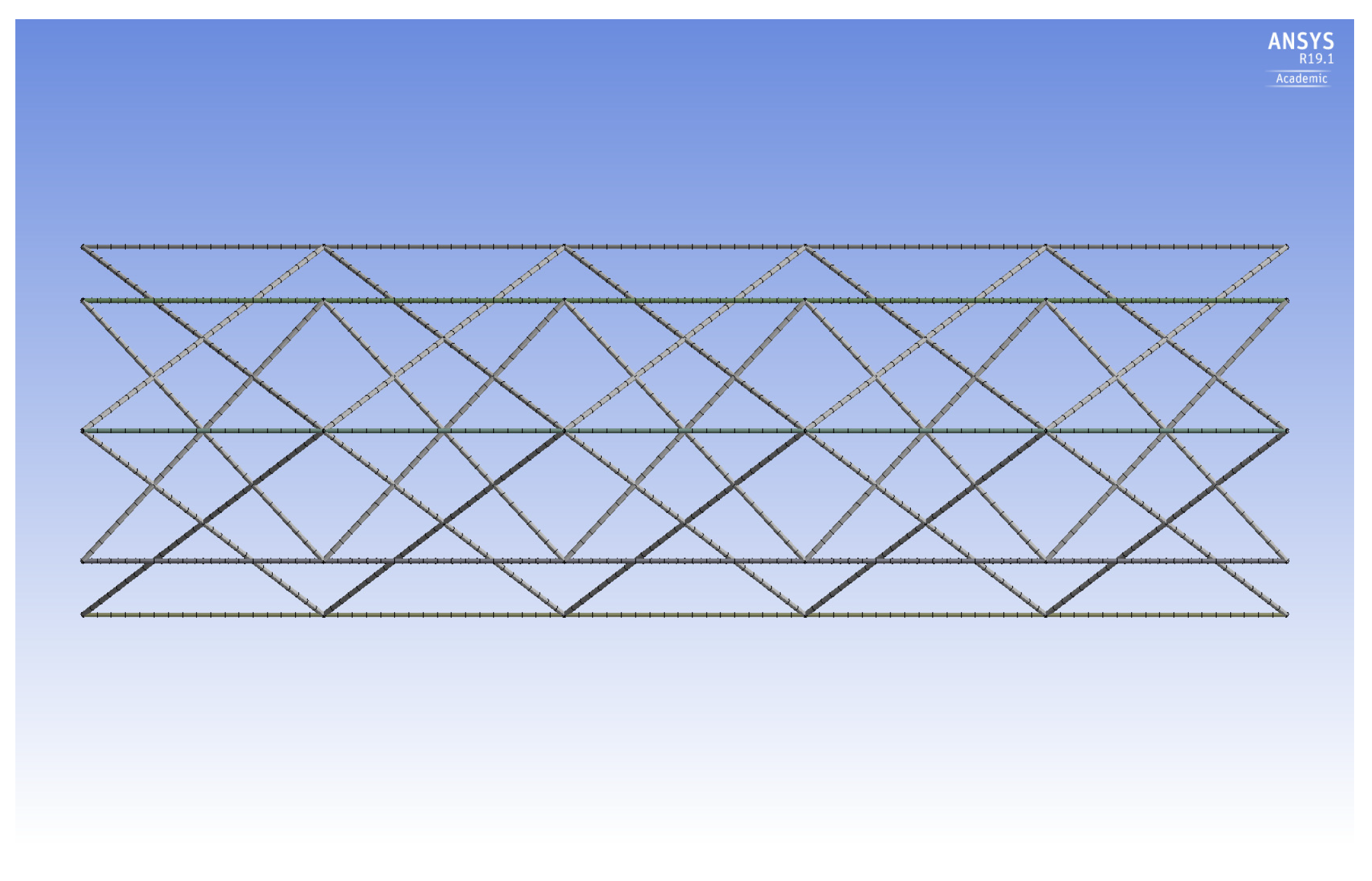
26]) to the design of IsoTruss structures with outer longitudinal members. The outer longitudinal configuration (OLC) possesses the same geometric characteristics as the inner longitudinal configuration (ILC) except that the longitudinal members are placed at the outer diameter of the structure, spanning between the nodes.
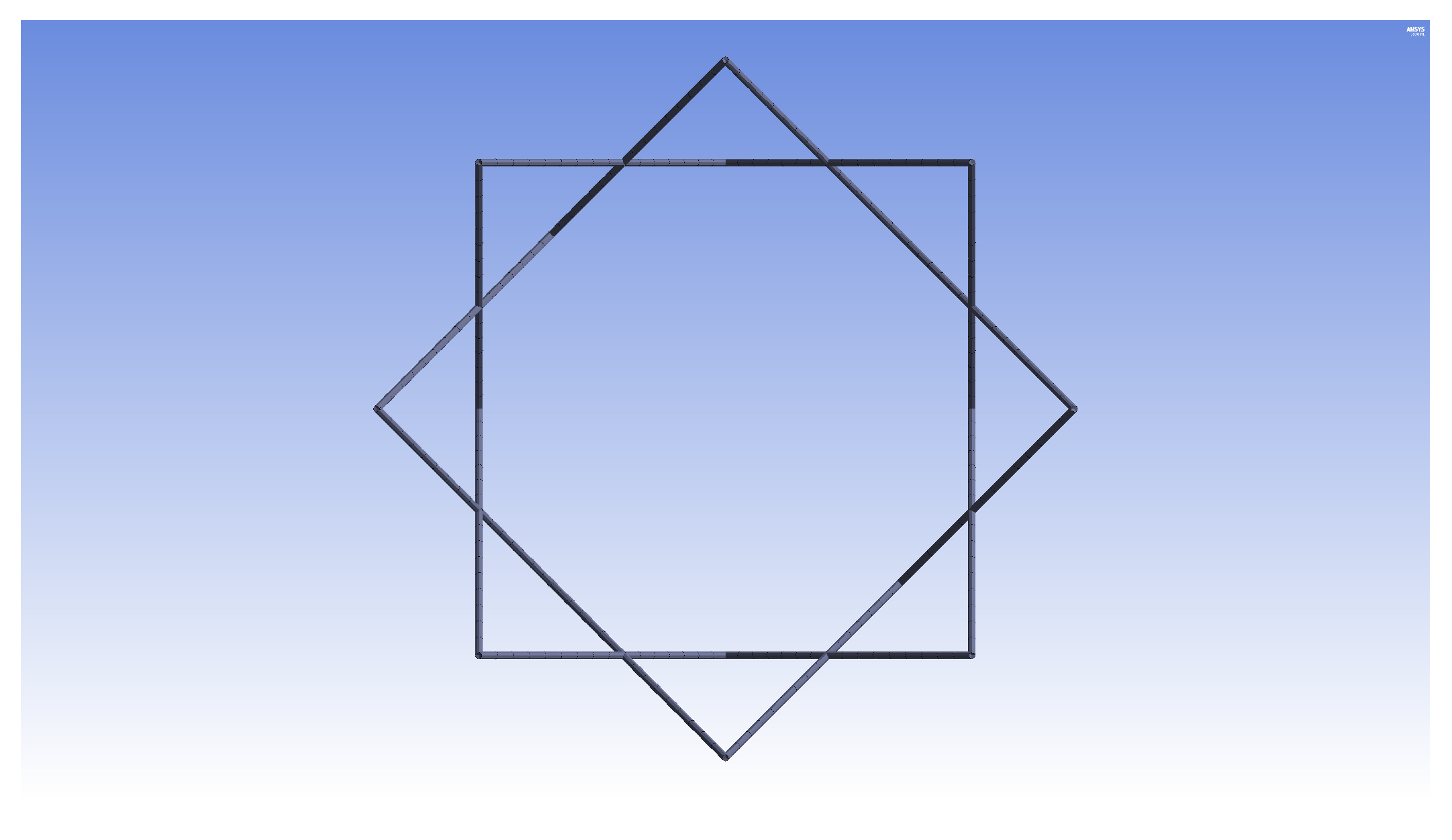
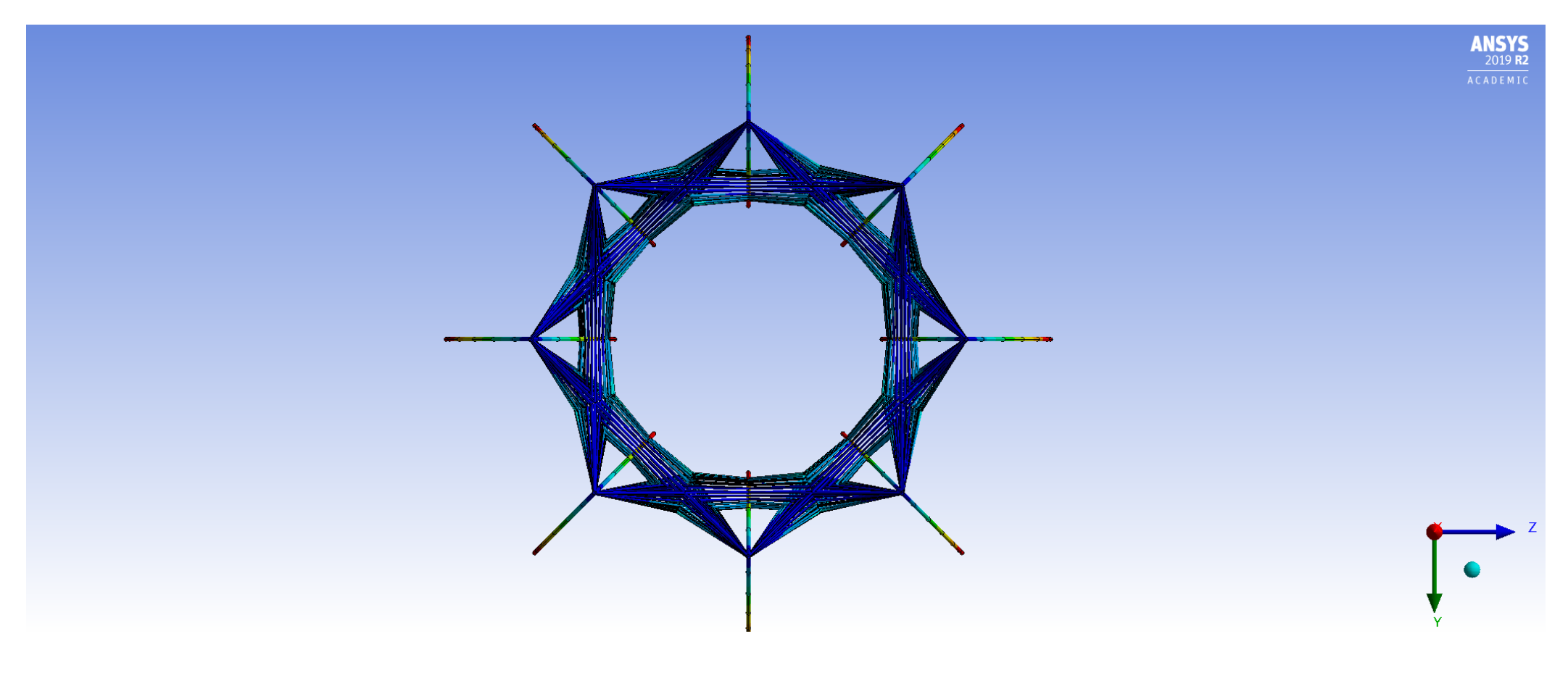
Figure 1 is the end view of an IsoTruss structure. A side view of the OLC is shown in
Figure 2. Refer to the works presented by Kesler and Opdahl for more explanation of IsoTruss orientation and geometry [
26,
40].
OLC and ILC structures of equal bay length, outer diameter, and member radii are equivalent in mass. By pushing the longitudinal members to the outer diameter, the global moment of inertia of the structure is increased without increasing the mass. Hence, the OLC is inherently more resistant to global buckling than the ILC of equal dimensions. On the other hand, the placement of the longitudinal members in the OLC increases the span of the longitudinal struts, thereby increasing the susceptibility to local buckling.
Due to inherent manufacturing complexity, experimental testing has not been widely performed on the OLC, therefore, there is limited physical data to demonstrate the structural performance and buckling behavior. The current study produces data from dimensional analysis (akin to that performed by Opdahl and Jensen [
39]), FE modeling, and optimization techniques (based on the framework presented in [
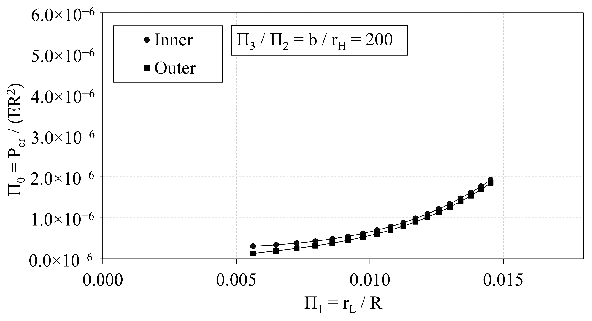
26]) to explore four subtopics. First, the data are used to characterize trends between the OLC design parameters and the buckling capacity. Second, FE predictions are plotted with analytical predictions to verify the accuracy of an analytical expression presented herein. Third, the relative performance of the OLC with respect to the ILC is analyzed via dimensional analysis. Finally, the OLC and ILC are optimized with respect to mass (via gradient-based techniques) to indicate the distinct advantages of each configuration under the same loading criteria.
5. Conclusions
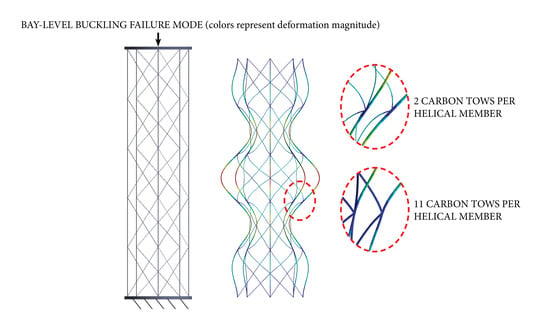
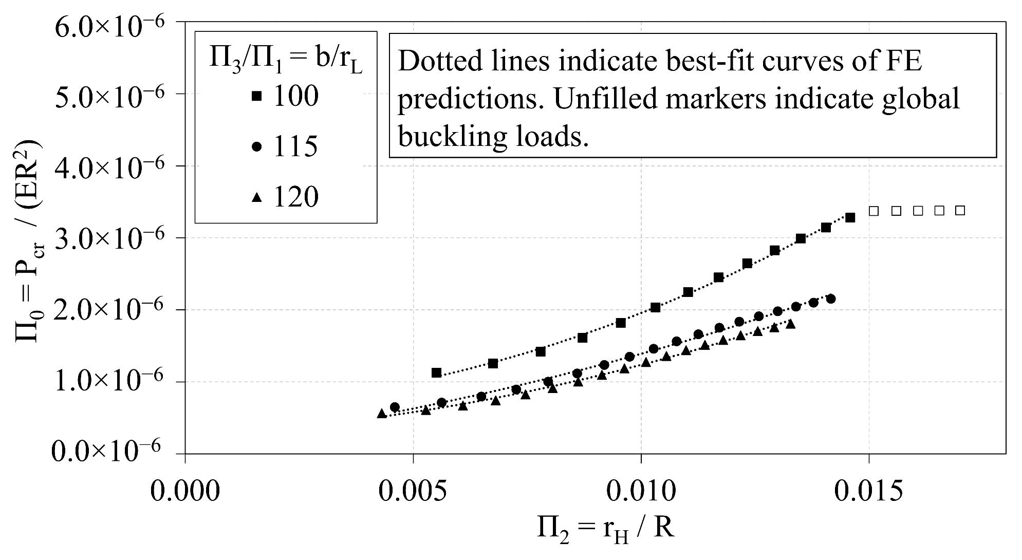
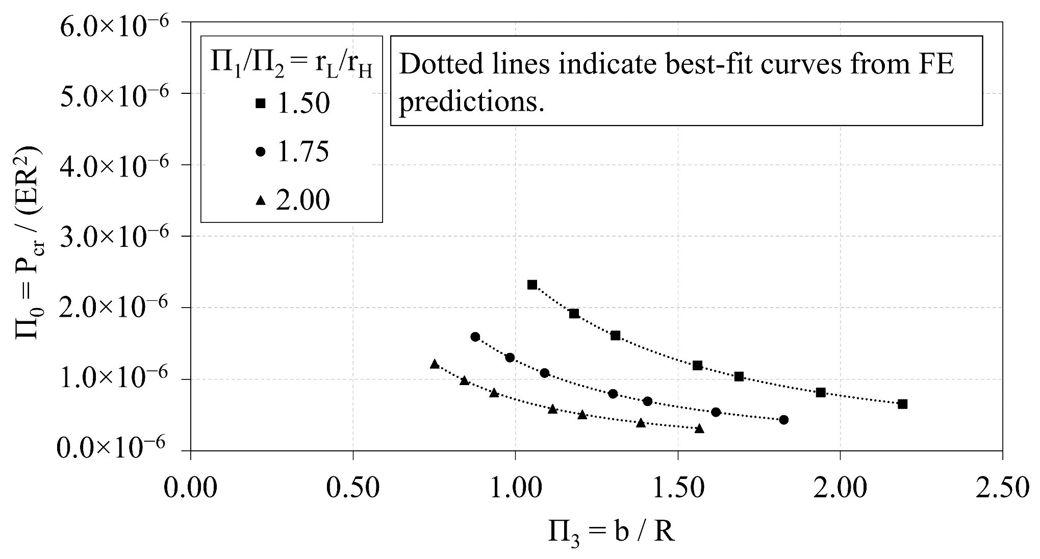
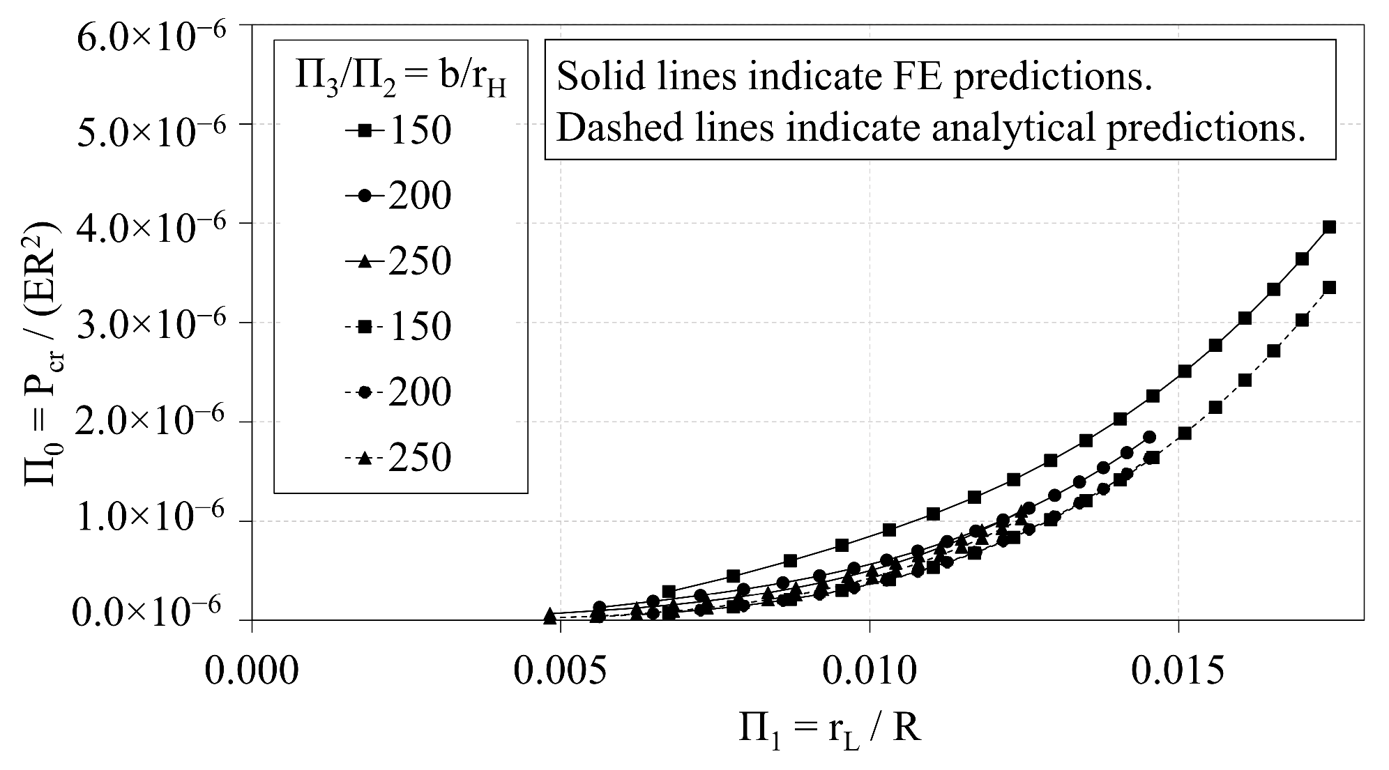
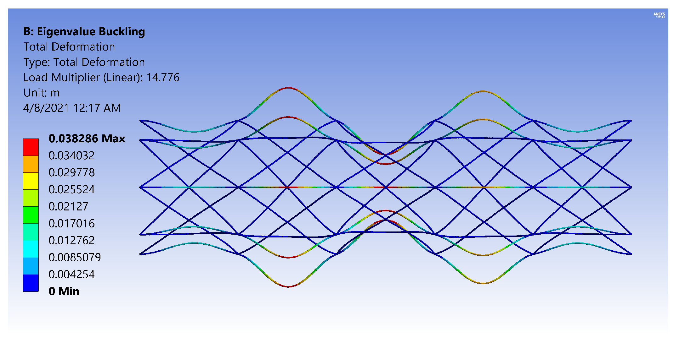
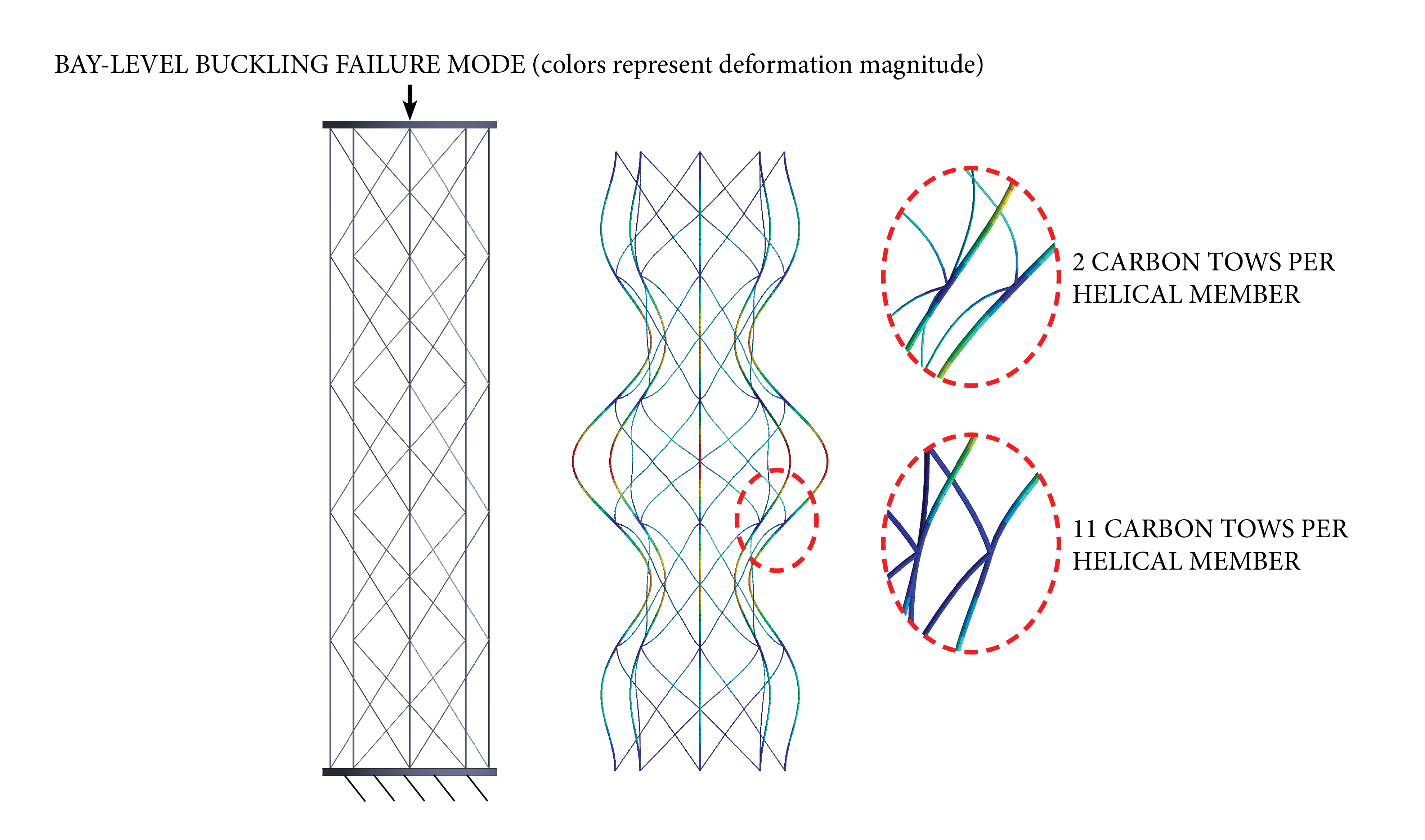
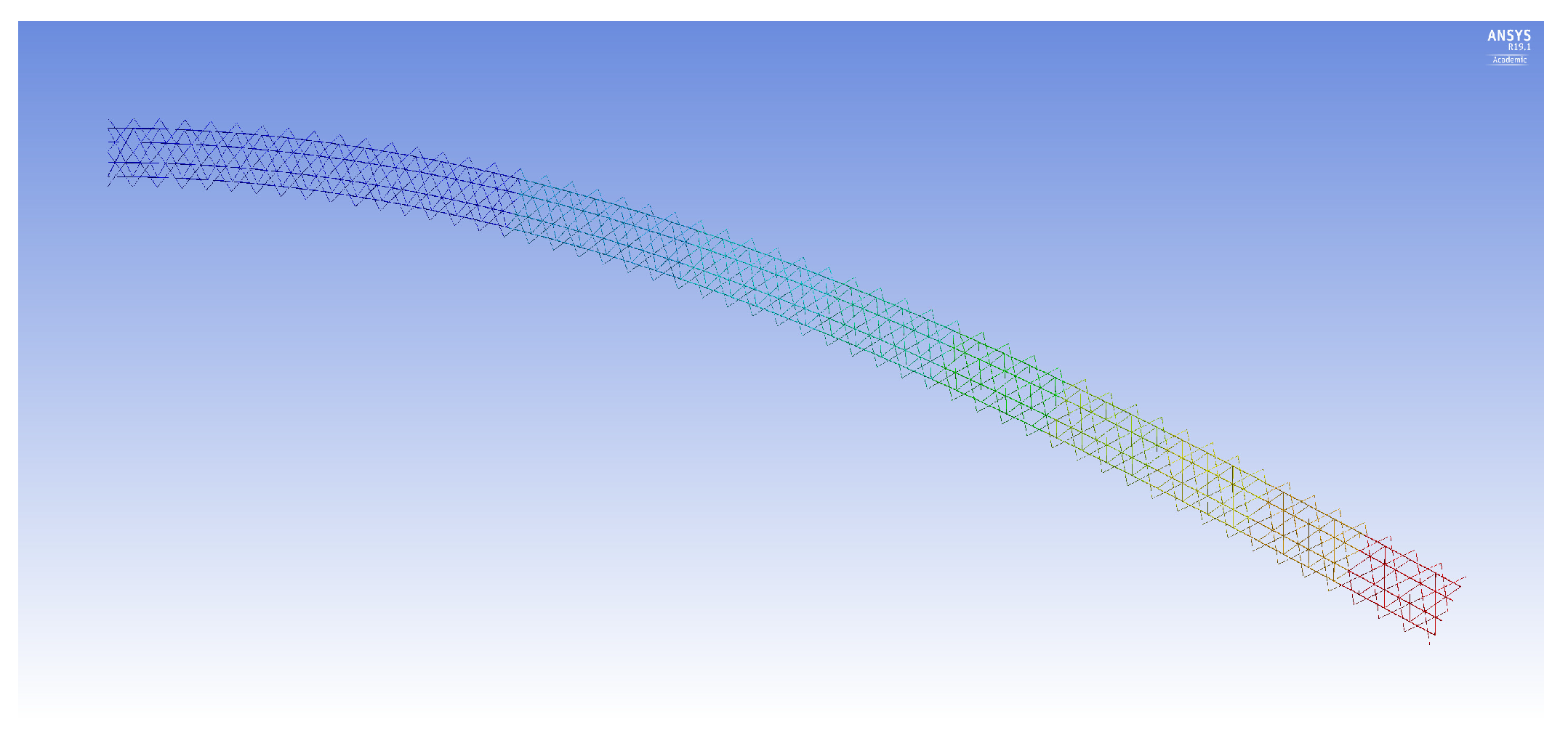
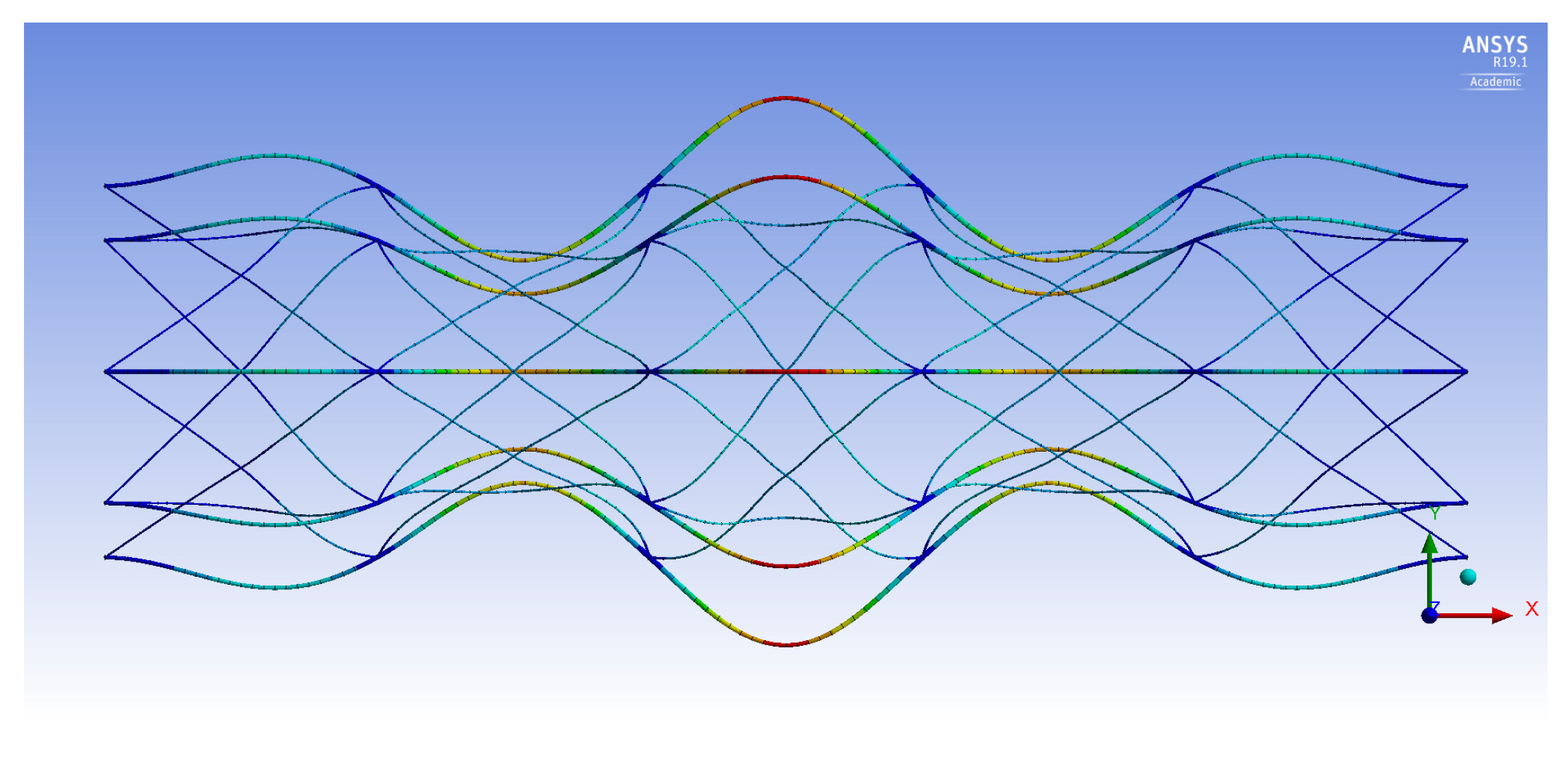
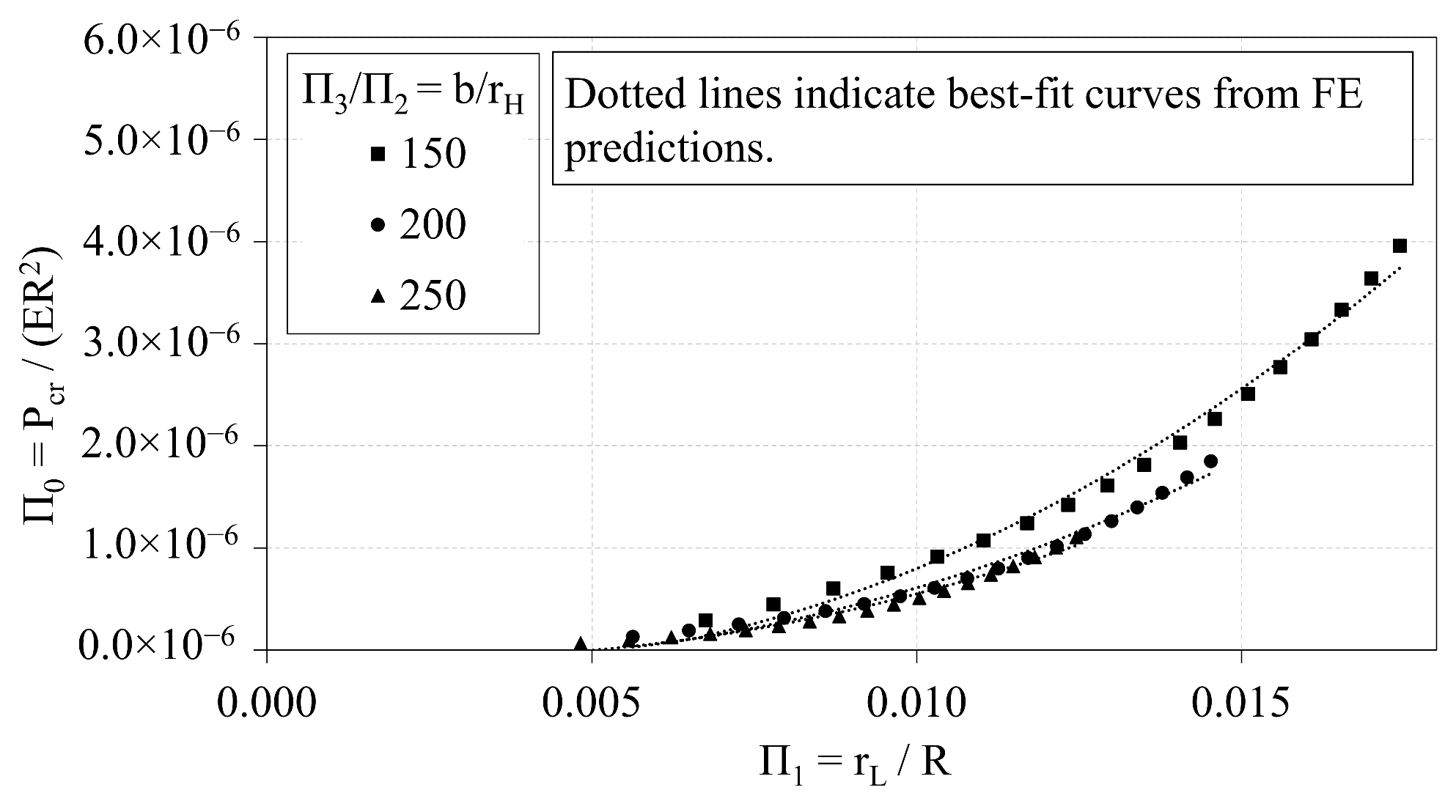
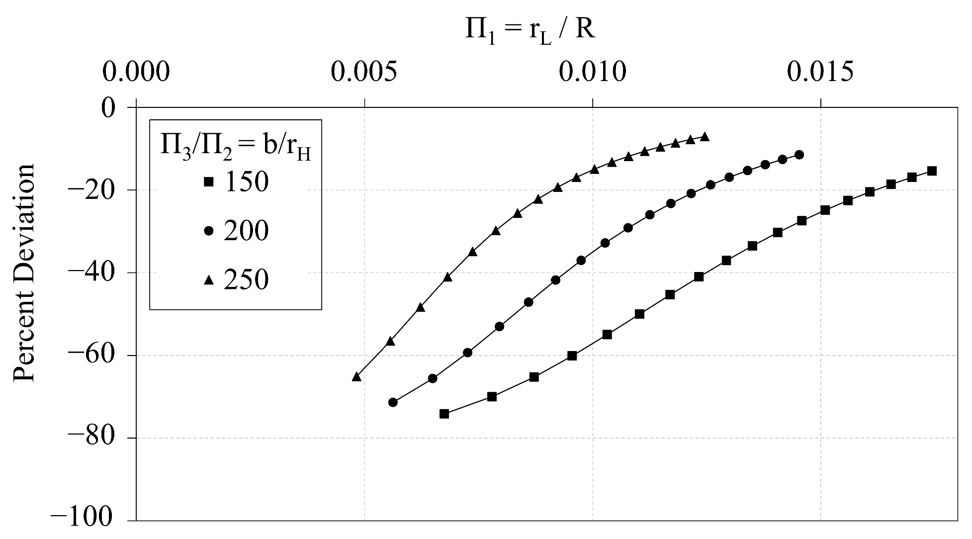
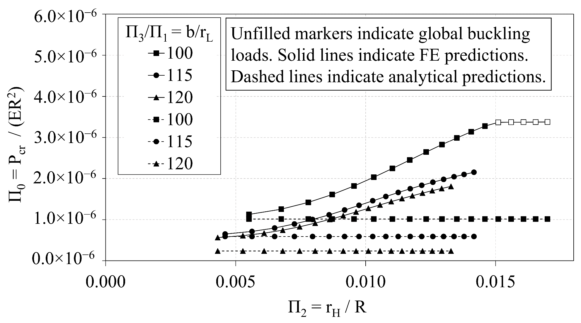
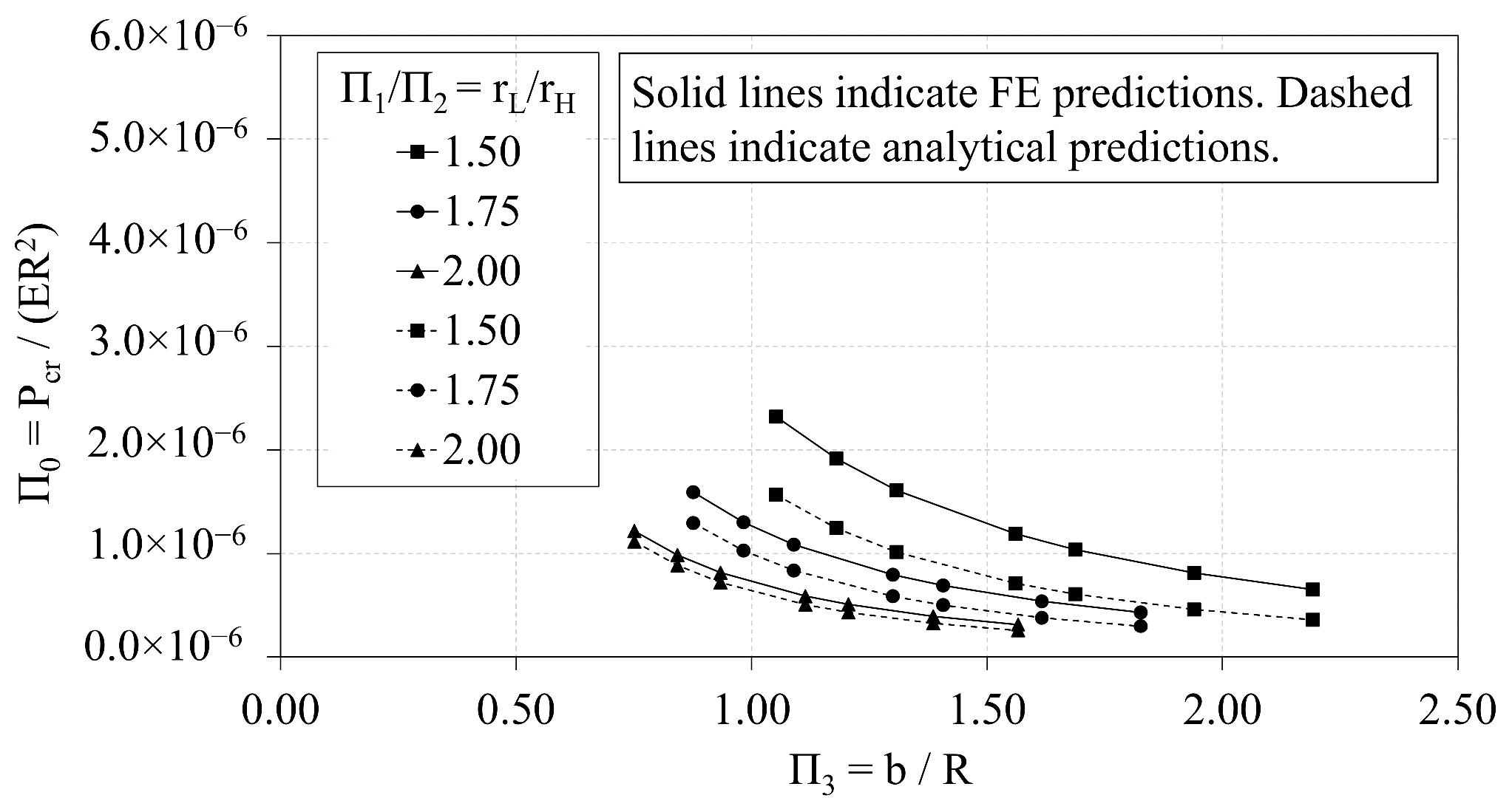
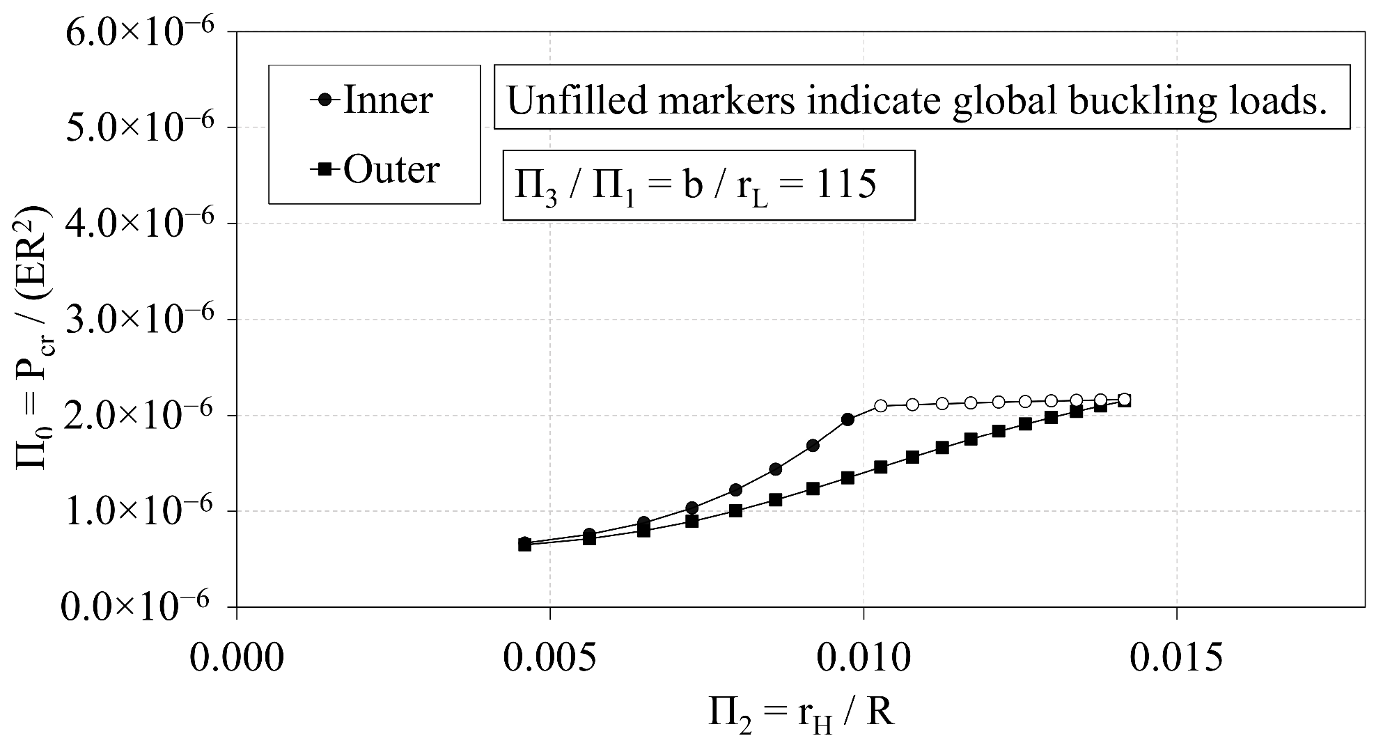
The purpose of the current study is to characterize the buckling behavior of 8-node IsoTruss structures with outer longitudinal members. A dimensional analysis is performed to analyze the interrelations between the governing design parameters and the critical buckling load. The critical buckling loads of diverse geometric dimensions are predicted using finite element (FE) modeling in ANSYS WorkBench. The best-fit curves that indirectly relate the longitudinal radius, the helical radius, and the bay length to the critical buckling load are characterized as quadratic and power expressions. The FE predictions are also plotted with analytical predictions to assess the accuracy of the analytical expression for bay-level buckling with respect to FE methods. Changes in the longitudinal radius and the bay length induce similar trends in the FE and analytical predictions. Increasing the helical radius, however, does not induce the same trends in the analytical and FE predictions. While increasing the helical radius increases the FE prediction, there is no change in the prediction from the analytical expression.
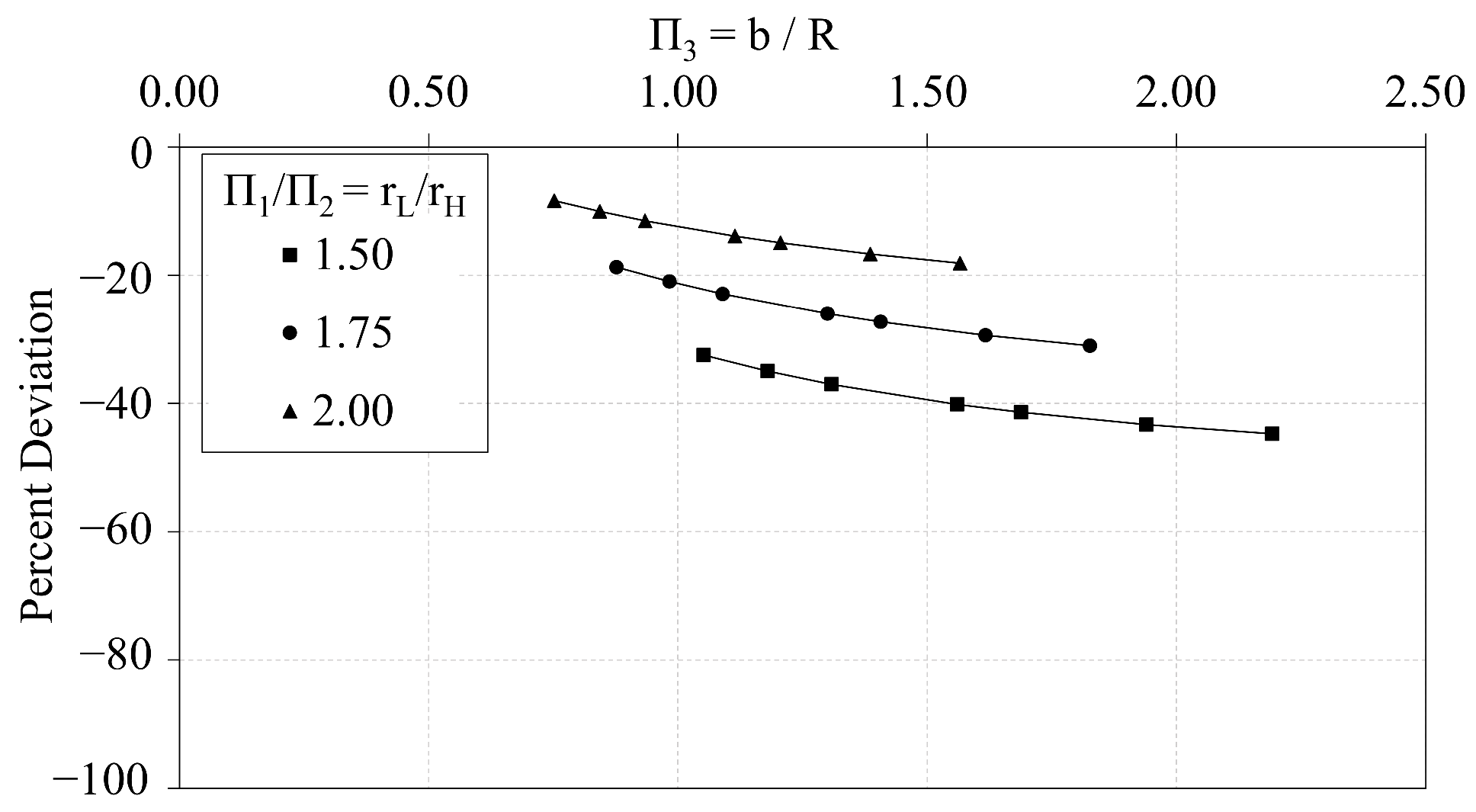
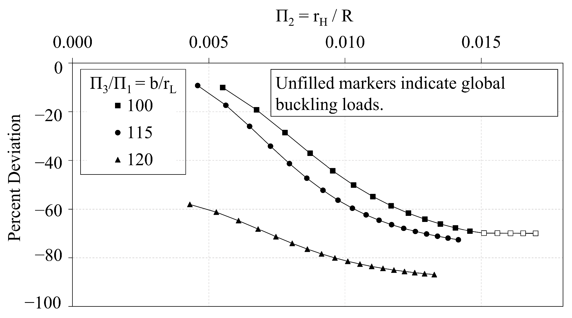
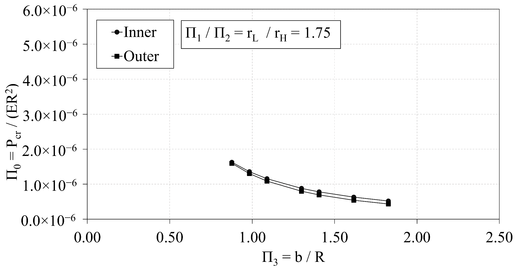
Trend analyses are also performed on corresponding 8-node IsoTruss structures with inner longitudinal members. The buckling data of the inner longitudinal configurations (ILC) are plotted with the data of the outer configurations (OLC) to analyze the relative performance of the configurations with respect to buckling resistance. Each plot indicates that the ILC has greater buckling resistance than the outer longitudinal counter-part within the design space of the trend analysis where the dimensions of the ILC and OLC are equivalent. The relative performance of the OLC and ILC is also analyzed by optimizing both configurations with respect to mass. The optimized structures are subject to the same bounds, and the constraints are defined by analytical expressions that predict the relevant buckling modes of each configuration. The optimized OLC has about 10.5% less mass than that of the optimized ILC.
Recommendations
First, a boundary constraint coefficient should be derived for the analytical expression that predicts local buckling in the OLC. The coefficient should incorporate the flexural rigidity of the helical members at the nodes, thereby capturing the effect of the helical radius on the buckling stability. Once derived, another trend analysis of can be performed to determine if the analytical expression and FE model predict similar trends in the local buckling load by varying . The improved analytical expression could be re-implemented in the gradient-based optimization code to improve the accuracy of the bay-level buckling constraint.
Second, additional research should be performed to delineate the design spaces where the ILC and OLC are preferred. While the results of the trend analyses indicate that the ILC has greater resistance to buckling than the OLC counter-part, the optimization analysis indicates that the optimized OLC has less mass than the optimized ILC. The advantage can be attributed to the fact that the OLC has a greater global moment of inertia than the ILC of equivalent outer radius. The design space could be delineated by performing a trend analysis with respect to the outer radius and the bay length.


