
Experimental Investigation of the TRM-to-Masonry Bond after Exposure to Elevated Temperatures: Cementitious and Alkali-Activated Matrices of Various Densities


Abstract
:1. Introduction
2. Materials and Methods
2.1. Substrate
2.2. TRM Overlays
2.3. Experimental Program
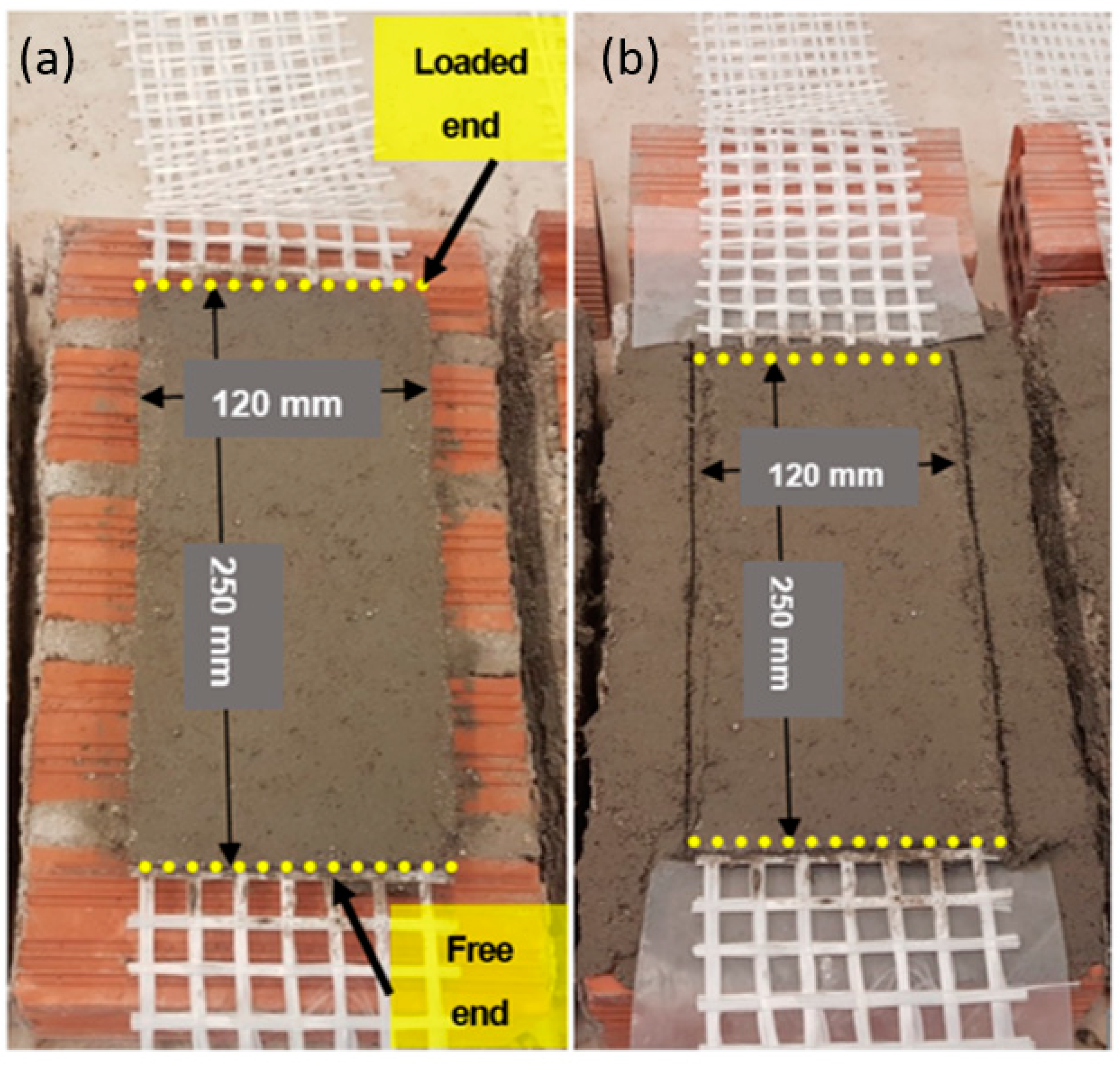
2.4. Specimens’ Construction
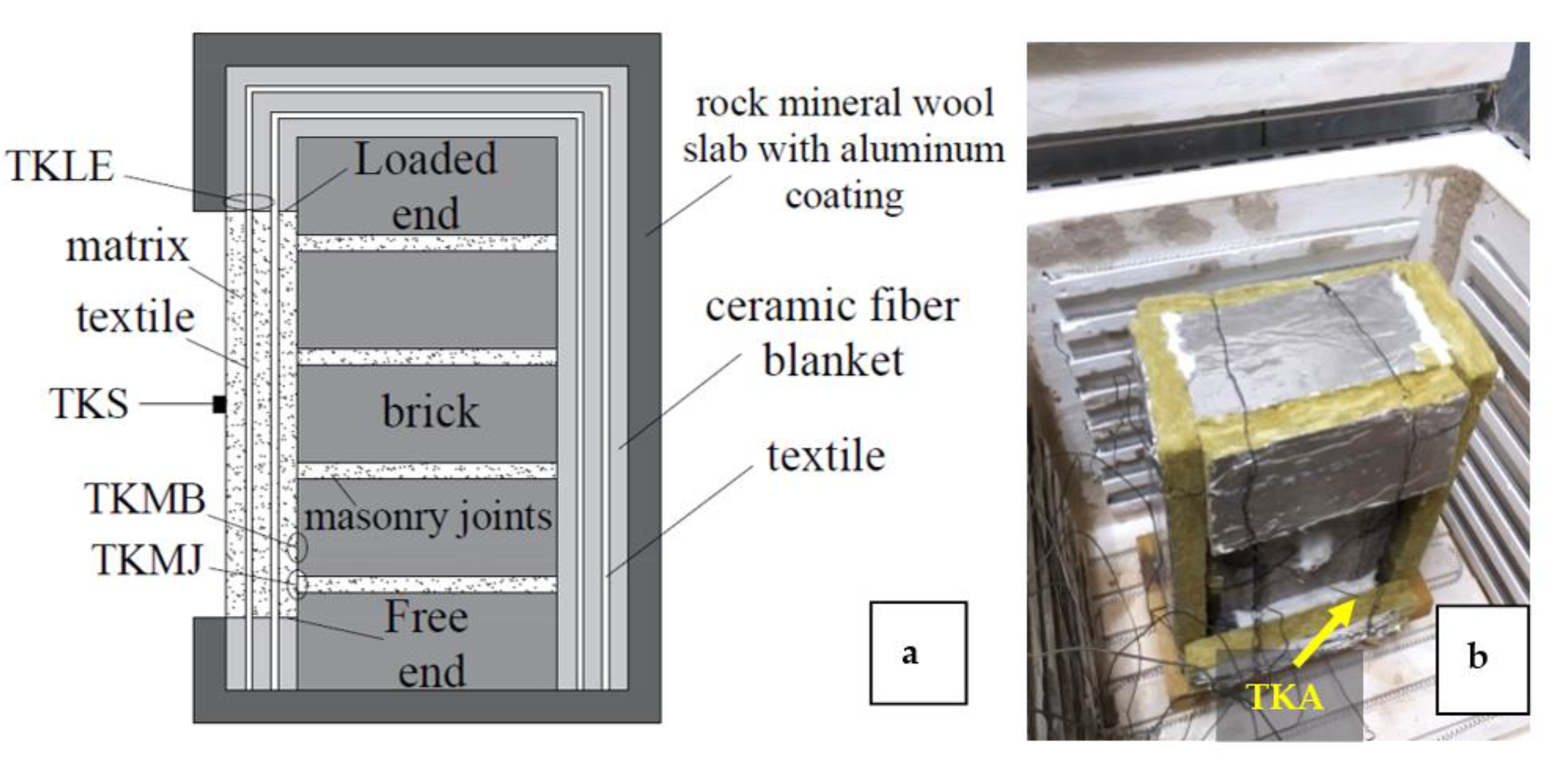
2.5. Thermal Treatment
2.5.1. Drying
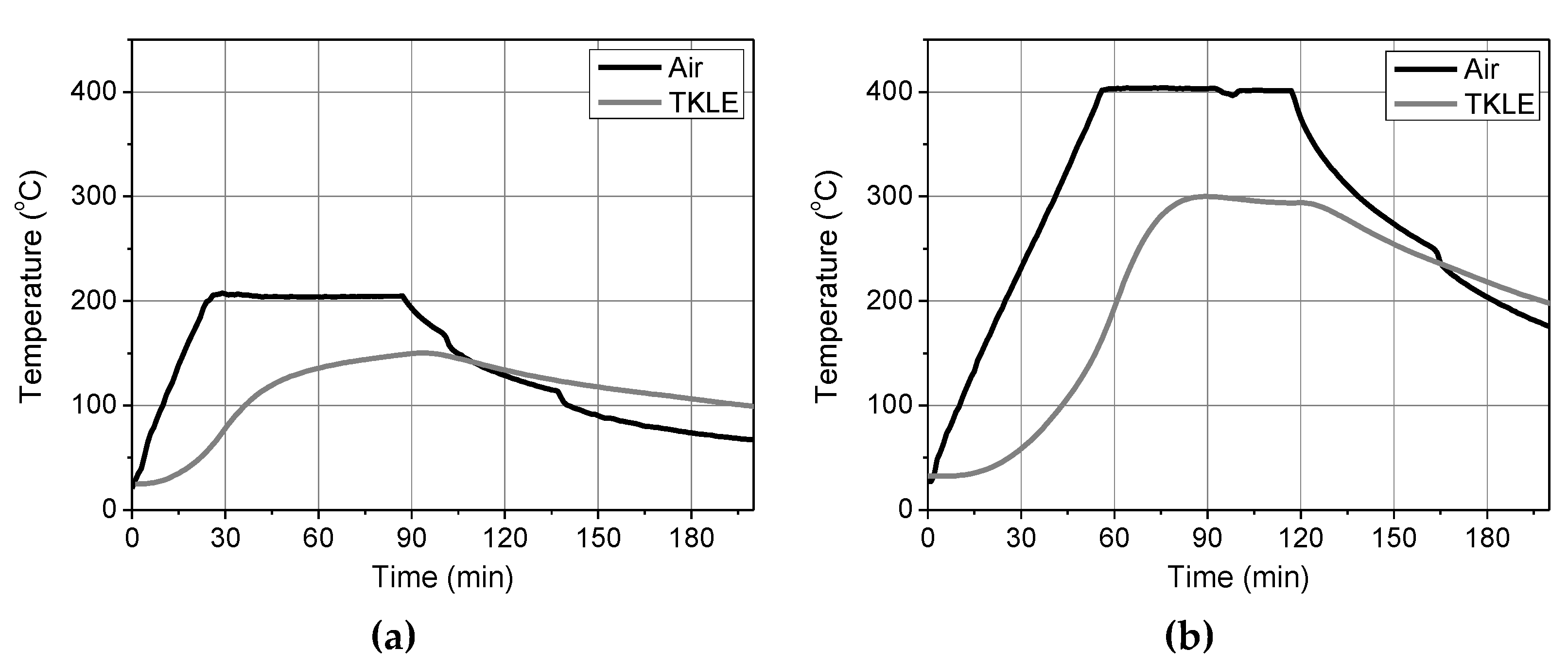
2.5.2. Heating
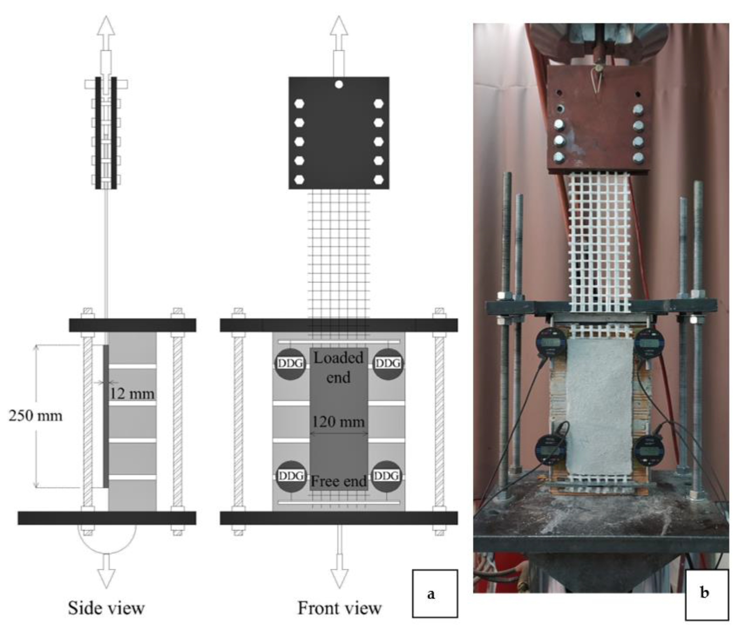
2.6. Shear Bond Tests
3. Experimental Results and Discussion
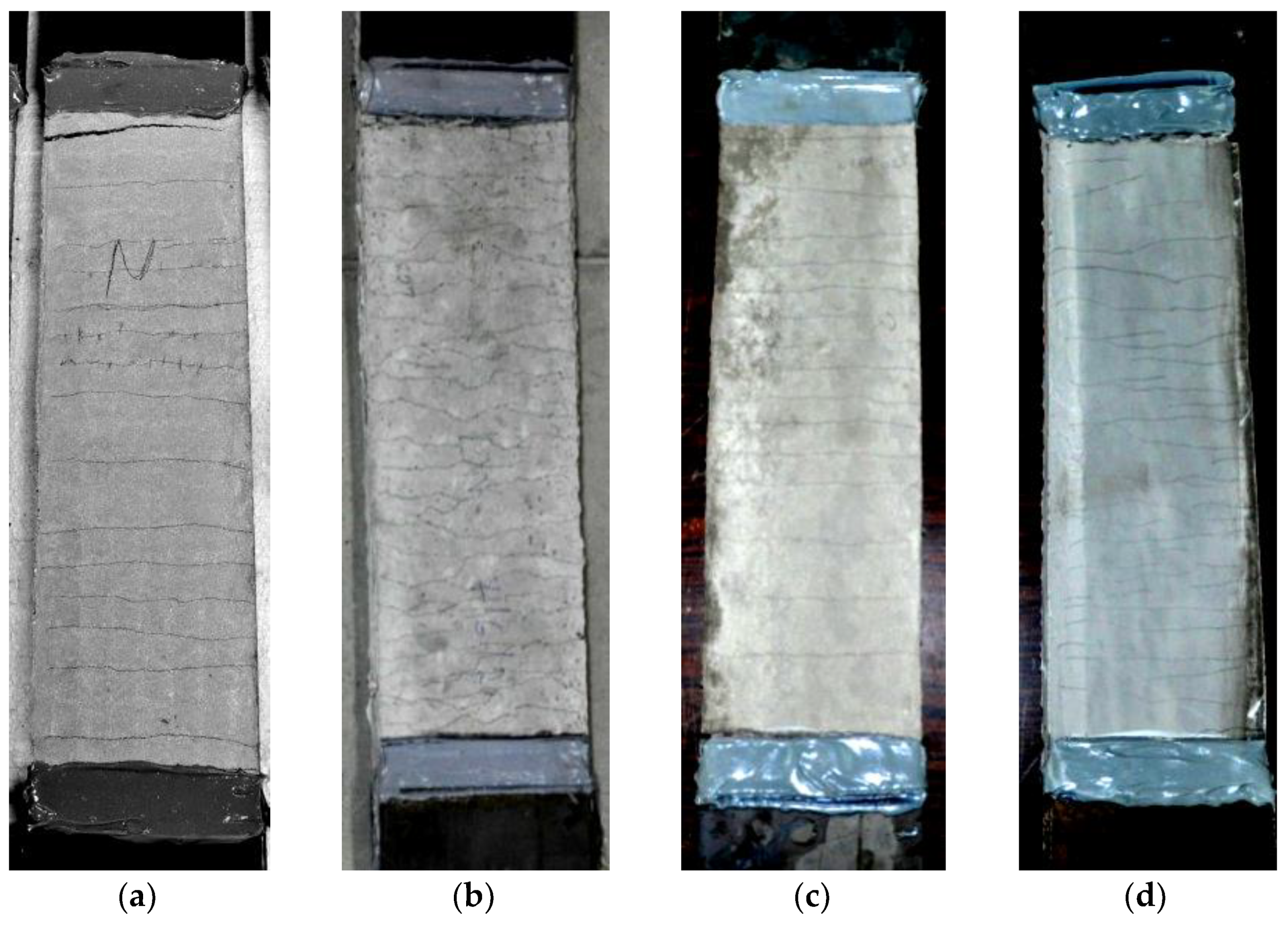
3.1. Visual Effect of Heating
3.2. Failure Mode
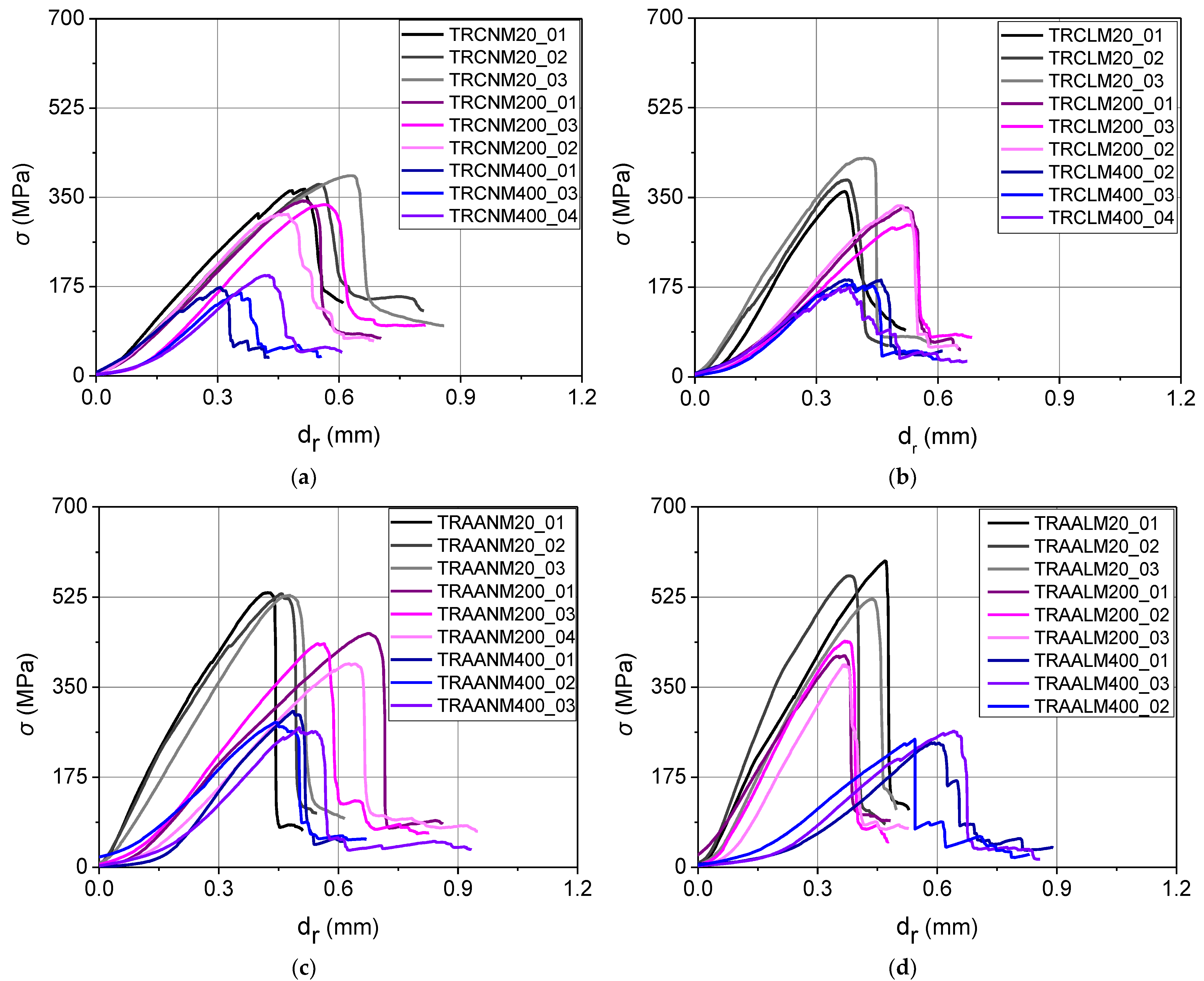
3.3. Stress vs. Relative Displacement Curves
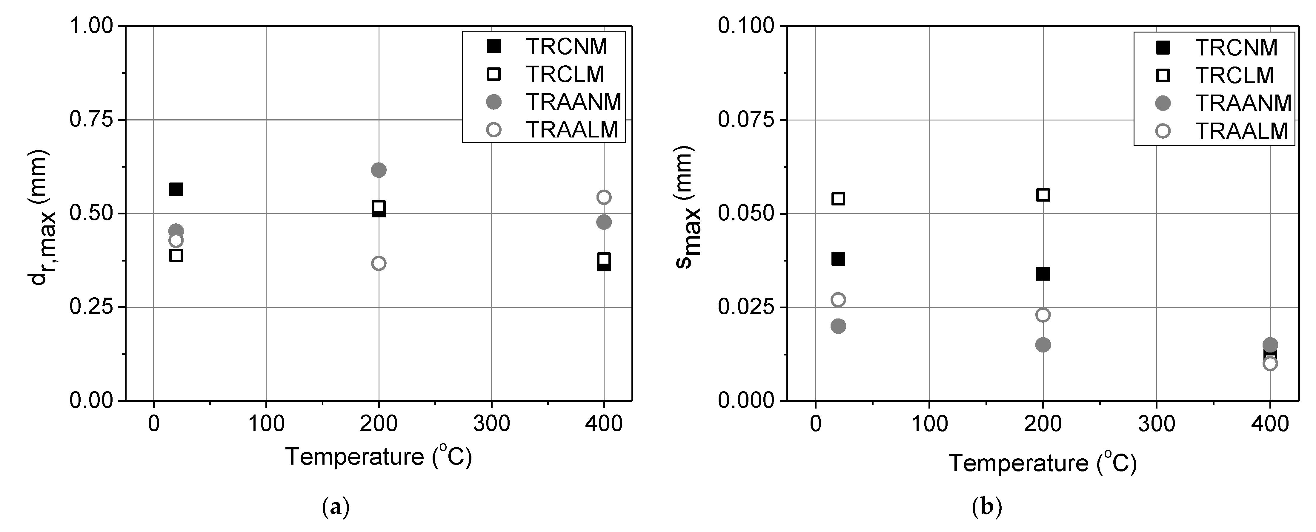
3.4. Other Performance Markers
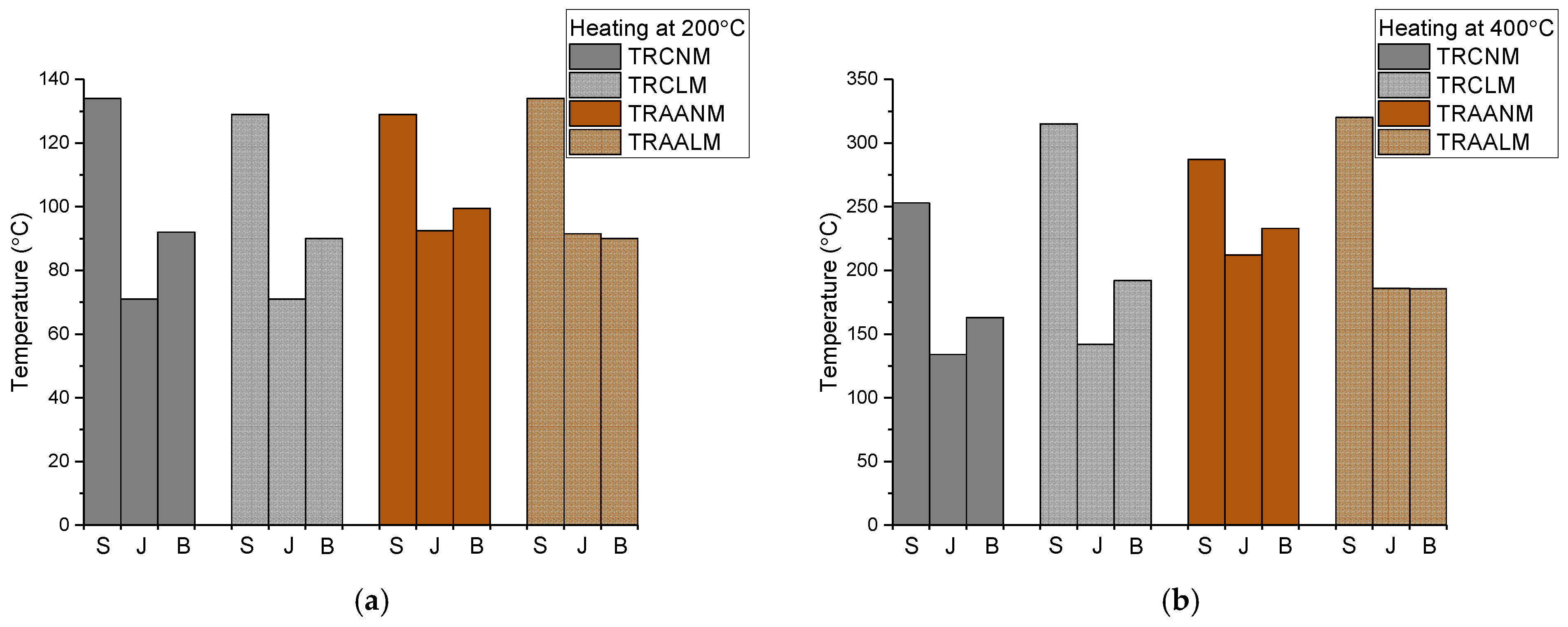
- The surface (TRM) temperature for all the specimens that were heated at 200 °C is the same (approx. equal to 130 °C). Heat protection of the masonry at the interface of the TRMs with the brick is also comparable between the systems. The same does not apply for the TRM/masonry joint interface, however. In this case, the cement-based systems provided better heat protection than the alkali-activated ones (this was also observed when heating at 400 °C–see further below for a plausible explanation). Different temperature readings (per TRM type) at the TRM/brick and TRM/masonry joint interfaces (present in all the specimen groups but the TRAALM ones) are owed to the stereoscopic heating of the masonry components and the different thermal properties of the bricks and masonry mortar.
- The surface (TRM) temperature for specimens that were heated at 400 °C seemed to depend upon the density class. TRMs with lightweight matrices developed: (i) identical surface temperatures regardless of the binder type that as used, and (ii) higher surface temperatures with regard to the TRMs comprising of normal-weight matrices of the same binder type. The latter is probably owed to the evaporation of the remaining moisture and chemically-bound water with vapors increasing the surface temperature. Nevertheless, per type of binder, the lightweight matrices resulted in either comparable (cement-based systems) or better (alkali-activated systems) heat protection at the TRM/masonry interface. As in the case of heating at 200 °C, the different temperatures were recorded (per TRM type) at the TRM/brick and TRM/joint interfaces for all the specimen groups but the TRAALM ones. The distinct behavior of alkali-activated lightweight matrices in this respect deserves further investigation to exclude the possibility of coincidental results. The fact that temperatures that were given by TKMJ for TRAALM and TRAANM were generally larger than the ones for TRCNM and TRCLM can possibly be explained as follows. In alkali-activated pastes, the weight loss occurs at temperatures below 300 °C; this phenomenon is related to the evaporation of chemically-bound water and to the significant thermal shrinkage. The latter occurs voluminously, hence, also thickness-wise resulting in decreased thermal insulation of the masonry block. Thermal cracking (more severe for alkali-activated mortars) also creates thermal bridges.
4. Conclusions
- Alkali-activated matrices proved to be good alternatives to cement-based ones for the production of strain-hardening inorganic matrix composites.
- Different types of matrices resulted in different heat-induced cracking potentials. In general, the lightweight matrices were more prone to cracking.
- Exposure to elevated temperatures did not alter the failure mode that was observed during the shear bond testing of unheated specimens which was due to sleeve fibers’ rupture along with core fibers’ slippage from the mortar.
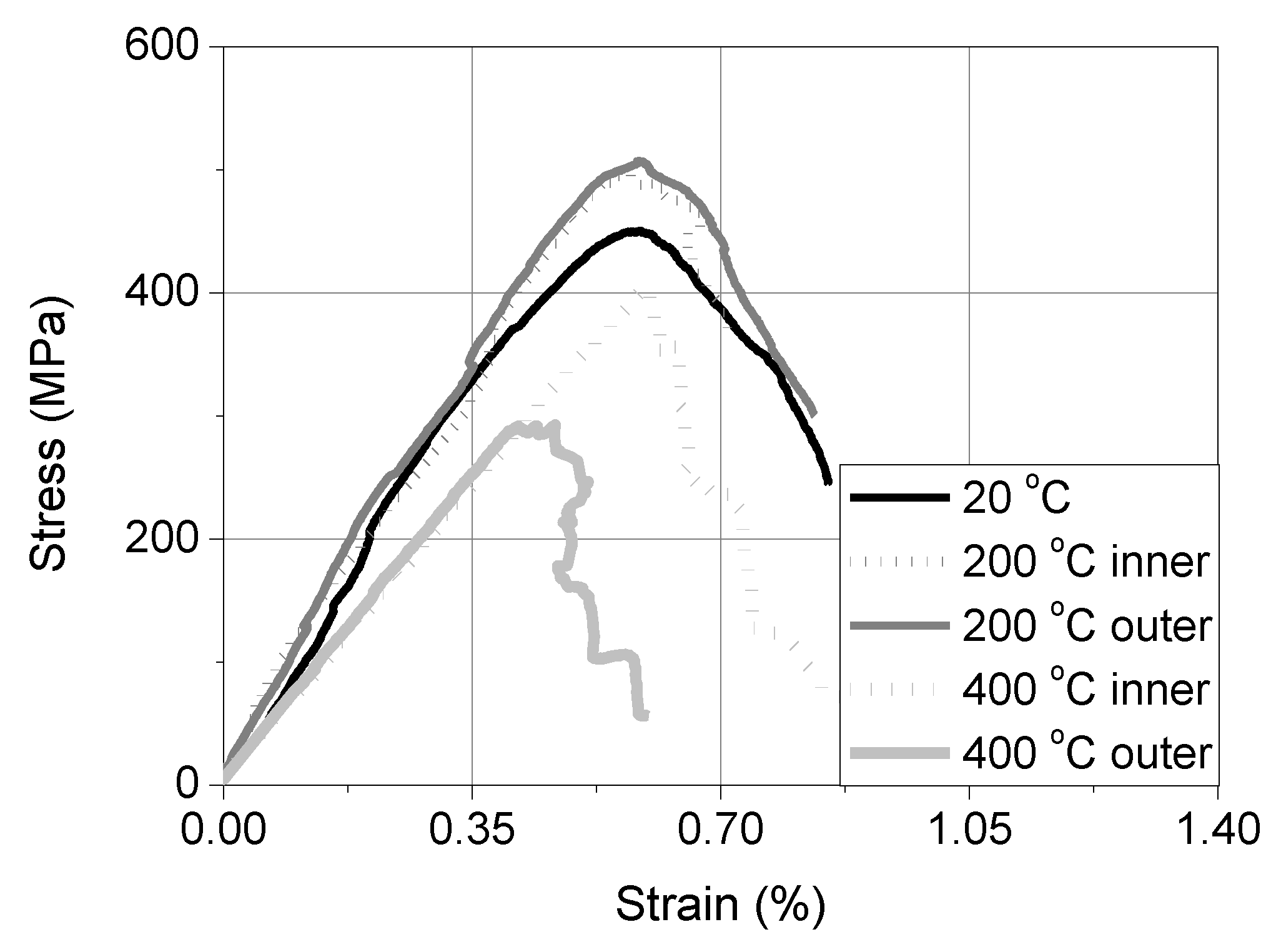
- Despite the fact that the projecting textile was insulated during the specimens’ heating, its tensile strength was compromised after exposure to 400 °C. Nevertheless, for all the heated specimens, the σmax values were lower than the tensile strength of the projecting textile that was heated at the same temperature; this denotes that failure was the result of matrix thermal damage.
- Should the heated projecting textile pose the weak link during shear bond loading, then the SL/SP test setup must either be redesigned or abandoned.
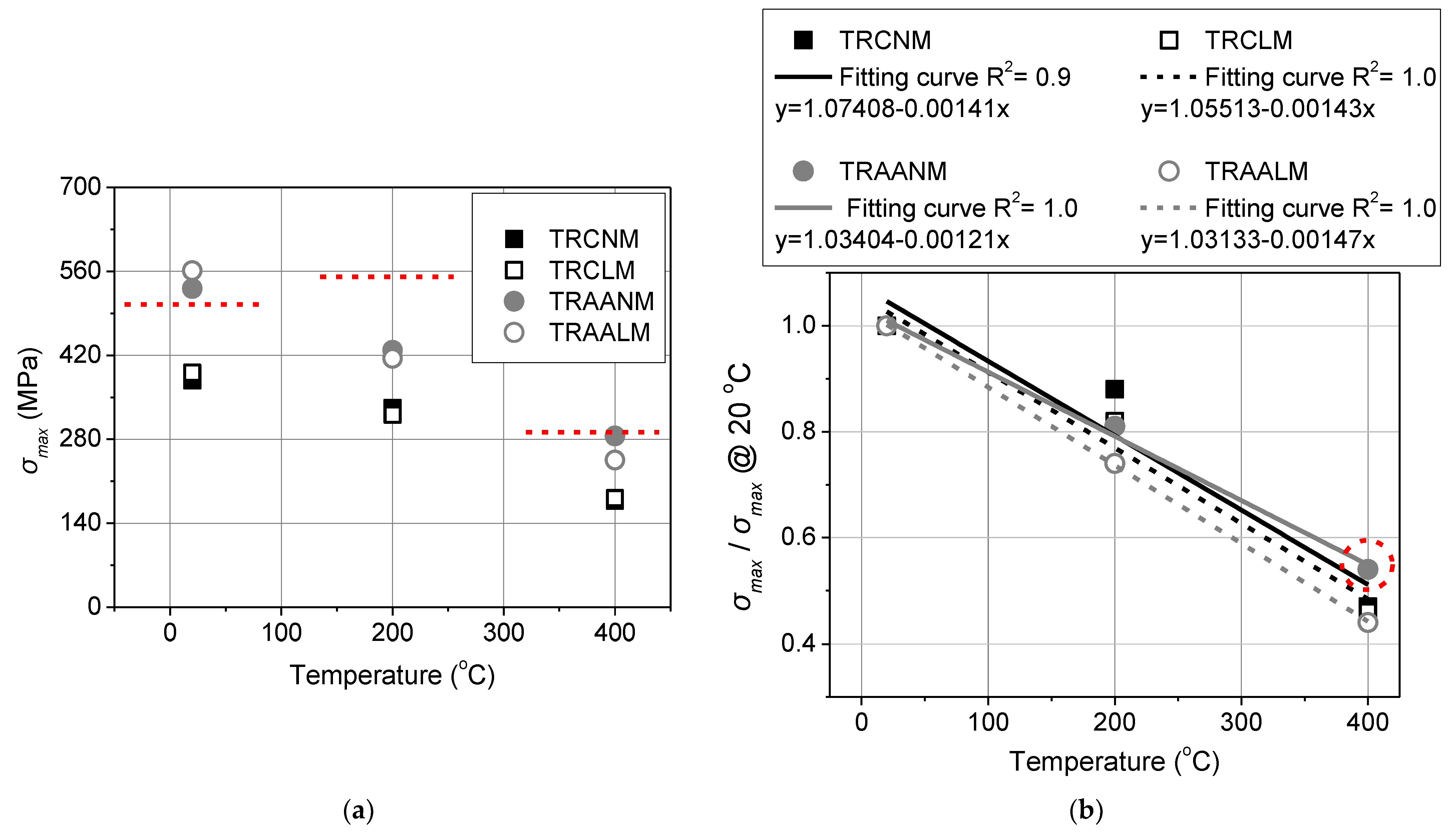
- The residual bond strength of TRM/masonry joints (TRM being either cement-based or alkali-activated) decreases as the exposure temperature increases.
- Specimens that were furnished with TRMs sharing the same binder exhibited (per exposure temperature) almost identical σmax values irrespective of their density class.
- The alkali-activated textile-reinforced mortars outperform their cement-based counterparts in terms of σmax, at every temperature.
- In terms of the residual bond strength that is expressed as a ratio of the bond strength after heating over the reference (unheated) one, all the systems retained close to 50% of their original strength after heating at 400 °C. The ratio decreases linearly with increasing temperature for all TRM systems.
- Per type of binder, the lightweight matrices resulted in either comparable (cement-based systems) or better (alkali-activated systems) heat protection at the TRM/masonry interface.
Author Contributions
Funding
Acknowledgments
Conflicts of Interest
References
- Bournas, D. Strengthening of existing structures: Selected case studies. In Textile Fibre Composites in Civil Engineering; Triantafillou, T., Ed.; Woodhead Publishing: England, UK, 2016; pp. 389–411. [Google Scholar]
- Bisby, L.; Stratford, T.; Hart, C.; Farren, S. Fire performance of well-anchored TRM, FRCM and FRP flexural strengthening systems. In Advanced Composites in Construction; Network Group for Composites in Construction: Chesterfield, UK, 2013; p. 113. [Google Scholar]
- Raoof, S.M.; Bournas, D.A. TRM versus FRP in flexural strengthening of RC beams: Behaviour at high temperatures. Constr. Build. Mater. 2017, 154, 424–437. [Google Scholar] [CrossRef]
- Tetta, Z.C.; Bournas, D.A. TRM vs. FRP jacketing in shear strengthening of concrete members subjected to high temperatures. Compos. B. Eng. 2016, 106, 190–205. [Google Scholar] [CrossRef]
- Michels, J.; Zwicky, D.; Scherer, J.; Harmanci, Y.E.; Motavalli, M. Structural Strengthening of Concrete with Fiber Reinforced Cementitious Matrix (FRCM) at Ambient and Elevated Temperature—Recent Investigations in Switzerland. Adv. Struct. Eng. 2014, 17, 1785–1799. [Google Scholar] [CrossRef]
- DIN 4102–2; Brandverhalten von Baustoffen und Bauteilen, Bauteile, Begriffe, Anforderungen und Prüfungen, Normenzum Brandverhalten von Baustoffen und Bauteilen: Baunetz, German, 1977.
- Cerniauskas, G.; Tetta, Z.; Bournas, D.A.; Bisby, L.A. Concrete confinement with TRM versus FRP jackets at elevated temperatures. Mater. Struct. 2020, 53, 58. [Google Scholar] [CrossRef]
- Ombres, L.; Mazzuca, P.; Verre, S. Effects of Thermal Conditioning at High Temperatures on the Response of Concrete Elements Confined with a PBO-FRCM Composite System. J. Mater. Civ. Eng. 2022, 34, 04021413. [Google Scholar] [CrossRef]
- Triantafillou, T.C.; Karlos, K.; Kefalou, K.; Argyropoulou, E. An innovative structural and energy retrofitting system for URM walls using textile reinforced mortars combined with thermal insulation: Mechanical and fire behavior. Constr. Build. Mater. 2017, 133, 1–13. [Google Scholar] [CrossRef]
- Maroudas, S.R.; Papanicolaou, C.G. Effect of High Temperatures on the TRM-to-Masonry Bond. Key Eng. Mater. 2017, 747, 533–541. [Google Scholar] [CrossRef]
- Ombres, L.; Iorfida, A.; Mazzuca, S.; Verre, S. Bond analysis of the thermally conditioned FRCM-masonry joints. Measurement 2018, 125, 509–515. [Google Scholar] [CrossRef]
- Askouni, P.D.; Papanicolaou, C.C.G.; Kaffetzakis, M.I. The Effect of Elevated Temperatures on the TRM-to-Masonry Bond: Comparison of Normal Weight and Lightweight Matrices. Appl. Sci. 2019, 9, 2156. [Google Scholar] [CrossRef] [Green Version]
- Donnini, J.; De Caso y Basalo, F.; Corinaldesi, V.; Lancioni, G.; Nanni, A. Fabric-reinforced cementitious matrix behavior at high-temperature: Experimental and numerical results. Compos. B Eng. 2017, 108, 108–121. [Google Scholar] [CrossRef] [Green Version]
- Ombres, L. Analysis of the bond between Fabric Reinforced Cementitious Mortar (FRCM) strengthening systems and concrete. Compos. B Eng. 2015, 69, 418–426. [Google Scholar] [CrossRef]
- Raoof, S.M.; Bournas, D.A. Bond between TRM versus FRP composites and concrete at high temperatures. Compos. B Eng. 2017, 127, 150–165. [Google Scholar] [CrossRef]
- Papanicolaou, C.G.; Triantafillou, T. Performance of TRM/TRC systems under elevated temperatures and fire conditions. ACI Spec. Publ. 2021, 345, 32–46. [Google Scholar]
- Askouni, P.D.; Papanicolaou, C.G. Textile Reinforced Mortar-to-masonry bond: Experimental investigation of bond-critical parameters. Constr. Build. Mater. 2019, 207, 535–547. [Google Scholar] [CrossRef]
- Carozzi, F.G.; Arboleda, D.; Poggi, C.; Nanni, A. Direct Shear Bond Tests of Fabric-Reinforced Cementitious Matrix Materials. J. Compos. Constr. 2020, 24, 04019061. [Google Scholar] [CrossRef]
- De Felice, G.; D’Antino, T.; De Santis, S.; Meriggi, P.; Roscini, F. Lessons Learned on the Tensile and Bond Behavior of Fabric Reinforced Cementitious Matrix (FRCM) Composites. Front. Built. Environ. 2020, 6, 1–15. [Google Scholar] [CrossRef]
- Trochoutsou, N.; Di Benedetti, M.; Pilakoutas, K.; Guadagninia, M. Bond of Flax Textile-Reinforced Mortars to Masonry. Constr. Build. Mater. 2021, 284, 122849. [Google Scholar] [CrossRef]
- D’Antino, T.; Sneed, L.H.; Carloni, C.; Pellegrino, C. Influence of the substrate characteristics on the bond behavior of PBO FRCM-concrete joints. Constr. Build. Mater. 2015, 101, 838–850. [Google Scholar] [CrossRef]
- D’Antino, T.; Gonzalez-Libreros, J.; Pellegrino, C.; Carloni, C.; Sneed, L.H. Performance of Different Types of FRCM Composites Applied to a Concrete Substrate. In Strain-Hardening Cement-Based Composites, SHCC 2017; Mechtcherine, V., Slowik, V., Kabele, P., Eds.; RILEM Book Series; Springer: Dordrecht, The Netherlands, 2018; Volume 15. [Google Scholar] [CrossRef] [Green Version]
- Raoof, S.M.; Koutas, L.N.; Bournas, D.A. Bond between textile-reinforced mortar (TRM) and concrete substrates: Experimental investigation. Compos. B. Eng. 2016, 98, 350–361. [Google Scholar] [CrossRef]
- Younis, A.; Ebead, U. Bond characteristics of different FRCM systems. Constr. Build. Mater. 2018, 175, 610–620. [Google Scholar] [CrossRef]
- Tamburini, S.; Natali, M.; Garbin, E.; Panizza, M.; Favaro, M.; Valluzzi, M.R. Geopolymer matrix for fibre reinforced composites aimed at strengthening masonry structures. Constr. Build. Mater. 2017, 141, 542–552. [Google Scholar] [CrossRef]
- Li, T.; Zhang, Y.; Dai, J.G. Flexural behavior and microstructure of hybrid basalt textile and steel fiber reinforced alkali-activated slag panels exposed to elevated temperatures. Constr. Build. Mater. 2017, 152, 651–660. [Google Scholar] [CrossRef]
- Longo, F.; Lassandro, P.; Moshiri, A.; Phatak, T.; Aiello, M.A.; Krakowiak, K.J. Lightweight geopolymer-based mortars for the structural and energy retrofit of buildings. Energy Build. 2020, 225, 110352. [Google Scholar] [CrossRef]
- CEN. EN 1996-1-1 Eurocode 6–Design of Masonry Structures–Part 1-1: General Rules for Reinforced and Unreinforced Masonry Structures; European Committee for Standardization: Brussels, Belgium, 2005.
- RILEM TC 76: Technical Recommendations for Testing and Use of Constructions Materials: LUMB1-Compressive Strength of Small Walls and Prisms; Chapman & Hall: London, UK, 1991.
- CEN. EN ISO 13934-1: Textiles-Tensile Properties of Fabrics–Part 1: Determination of Maximum Force and Elongation at Maximum Force Using the Strip Method; British Standard: Brussels, Belgium, 1999.
- CEN. EN 1015-11: Methods of Test for Mortar for Masonry–Part 11: Determination of Flexural and Compressive Strength of Hardened Mortar; European Committee for Standardization: Brussels, Belgium, 1993.
- AC434 ICC-ES: Masonry and Concrete Strengthening Using Fiber-Reinforced Cementitious Matrix (FRCM) Composite Systems; ICC-Evaluation Service: Whittier, CA, USA, 2016.
- De Felice, G.; Aiello, M.A.; Caggegi, C.; Ceroni, F.; De Santis, S.; Garbin, E.; Gattesco, N.; Hojdys, Ł.; Krajewski, P.; Kwiecień, A.; et al. Recommendation of RILEM Technical Committee 250-CSM: Test method for Textile Reinforced Mortar to substrate bond characterization. Mater. Struct. 2018, 51, 95. [Google Scholar] [CrossRef]


| Cementitious Matrix | Normal-Weight | Light Weight |
|---|---|---|
| Composition | kg/m3 | |
| Portland cement (CEM II 42.5 N) | 586 | 655 |
| Sand (dmax = 2 mm) * | 1047 (limestone) | 269 (expanded glass) |
| Silica fume (dmax = 1 μm) | 47 | 52 |
| Limestone filler (dmax = 120 μm) | 146 | 163 |
| Effective water ** | 344 | 266 |
| PVA fibers (6 mm) | 1.3 | 13 |
| Superplasticizer | 4.1 | 5 |
| Air-dry density | kg/m3 | |
| 2034 | 1202 | |
| Flexural strength at 28 days | MPa | |
| 7.3 | 5.7 | |
| Compressive strength at 28 days | MPa | |
| 61.6 | 23.6 | |
| Alkali-Activated Matrix | Normal-Weight | Light Weight |
| Composition | kg/m3 | |
| Metakaolin | 325 | 325 |
| Fly ash | 281 | 281 |
| Ladle furnace slag | 63 | 63 |
| Sand (dmax = 2 mm) * | 1113 (siliceous) | 250 (expanded glass) |
| Potassium waterglass | 375 | 375 |
| Potassium hydroxide pellets | 56 | 56 |
| Effective water ** | 200 | 225 |
| PVA fibers (6 mm) | 3 | 7 |
| Air-dry density | kg/m3 | |
| 1814 | 1001 | |
| Flexural strength at 28 days | MPa | |
| 6.8 | 5.3 | |
| Compressive strength at 28 days | MPa | |
| 46.3 | 16.7 | |
| Coupon’s TRM System | First Crack Stress | Axial Strain Corresponding to fFCR | Tensile Strength | Axial Strain Corresponding to fTRM |
|---|---|---|---|---|
| fFCR (MPa) | εFCR (%) | fTRM (MPa) | εTRM (%) | |
| [CoV] | [CoV] | [CoV] | [CoV] | |
| TRCNM | 327 [10%] | 0.026 [8%] | 604 [7%] | 1.105 [13%] |
| TRCLM | 167 [8%] | 0.039 [19%] | 740 [4%] | 1.232 [7%] |
| TRAANM | 297 [8%] | 0.084 [18%] | 667 [12%] | 1.033 [17%] |
| TRAALM | 152 [10%] | 0.092 [20%] | 819 [1%] | 1.556 [3%] |
| Specimen | TKLE [°C] | TKS [°C] | TKMB [°C] | TKMJ [°C] | σmax [MPa] | Average [CoV %] | dr,max [mm] | Average [CoV %] | smax [mm] | σmax/ftex [%] |
|---|---|---|---|---|---|---|---|---|---|---|
| TRCNM20_01 | 366 | 378 (4) | 0.515 | 0.564 (10) | 0.038 | 72 | ||||
| TRCNM20_02 | 376 | 0.549 | 74 | |||||||
| TRCNM20_03 | 393 | 0.627 | 78 | |||||||
| TRCNM200_01 | 54|111 | - | - | - | 343 | 332 (4) | 0.511 | 0.508 (11) | 0.034 | 62 |
| TRCNM200_02 | 54|118 | 99|134 | 47|92 | 34|71 | 317 | 0.451 | 58 | |||
| TRCNM200_03 | 67|142 | - | - | - | 336 | 0.561 | 61 | |||
| TRCNM400_01 | 157|267 | - | - | - | 173 | 178 (10) | 0.307 | 0.364 (17) | 0.012 | 59 |
| TRCNM400_02 | 177|266 | 147|253 | 89|163 | 77|134 | 162 | 0.358 | 55 | |||
| TRCNM400_03 | 106|252 | 153|256 | - | 197 | 0.427 | 67 | ||||
| TRCLM20_01 | 362 | 391 (8) | 0.369 | 0.388 (7) | 0.054 | 72 | ||||
| TRCLM20_02 | 384 | 0.375 | 76 | |||||||
| TRCLM20_03 | 427 | 0.419 | 85 | |||||||
| TRCLM200_01 | 59|105 | 98|129 | 51|90 | 36|71 | 332 | 321 (7) | 0.515 | 0.518 (3) | 0.055 | 60 |
| TRCLM200_02 | 74|123 | 91|129 | - | - | 334 | 0.503 | 61 | |||
| TRCLM200_03 | 48|98 | 297 | 0.535 | 54 | ||||||
| TRCLM400_01 | 124|231 | - | - | - | 190 | 182 (4) | 0.380 | 0.378 (1) | 0.011 | 65 |
| TRCLM400_02 | 111|223 | 220|315 | 90|192 | 73|142 | 181 | 0.375 | 62 | |||
| TRCLM400_03 | 144|256 | 217|317 | - | 174 | 0.381 | 60 | ||||
| TRAANM20_01 | 534 | 531 (1) | 0.423 | 0.453 (6) | 0.020 | 106 | ||||
| TRAANM20_02 | 532 | 0.459 | 105 | |||||||
| TRAANM20_03 | 529 | 0.478 | 105 | |||||||
| TRAANM200_01 | 80|154 | 85|129 | 50|101 | 50|97 | 454 | 428 (7) | 0.674 | 0.616 (10) | 0.015 | 82 |
| TRAANM200_02 | 58|145 | - | - | - | 396 | 0.548 | 72 | |||
| TRAANM200_03 | 66|148 | 89|129 | 51|98 | 43|88 | 435 | 0.626 | 79 | |||
| TRAANM400_01 | 183|265 | - | - | - | 303 | 286 (6) | 0.486 | 0.477 (6) | 0.015 | 104 |
| TRAANM400_02 | 187|264 | - | - | - | 282 | 0.443 | 97 | |||
| TRAANM400_03 | 174|254 | 184|287 | 126|233 | 134|212 | 271 | 0.502 | 93 | |||
| TRAALM20_01 | 595 | 561 (7) | 0.469 | 0.428 (11) | 0.027 | 118 | ||||
| TRAALM20_02 | 567 | 0.378 | 112 | |||||||
| TRAALM20_03 | 522 | 0.437 | 103 | |||||||
| TRAALM200_01 | 47|112 | 90|135 | 51|87 | 42|90 | 411 | 415 (6) | 0.366 | 0.367 (0.1) | 0.023 | 75 |
| TRAALM200_02 | 67|146 | - | - | - | 440 | 0.367 | 80 | |||
| TRAALM200_03 | 42|116 | 87|133 | 44|93 | 43|93 | 394 | 0.367 | 72 | |||
| TRAALM400_01 | 155|236 | - | - | - | 242 | 246 (2) | 0.586 | 0.591 (8) | 0.010 | 83 |
| TRAALM400_02 | 167|299 | 245|321 | 89|175 | 110|177 | 249 | 0.544 | 85 | |||
| TRAALM400_03 | 173|283 | 254|319 | 99|196 | 91|195 | 265 | 0.642 | 91 |
| Temperature [°C] | Tensile Strength ftex (MPa) [CoV] | Elastic Module Etex (GPa) [CoV] |
|---|---|---|
| 20 | 505 [11%] | 83 [18%] |
| 200 inner strip | 551 [14%] | 85 [15%] |
| 200 outer strip | 569 [16%] | 87 [0.1%] |
| 400 inner strip | 401 [1%] | 74 [7%] |
| 400 outer strip | 292 [1%] | 71 [12%] |
| Temperature | 200 °C | 400 °C | |
|---|---|---|---|
| System | |||
| TRCNM | No cracks | No cracks | |
| TRCLM | A limited number of cracks (maximum depth < thickness of the top mortar layer) | Numerous cracks (maximum depth = thickness of the top mortar layer) | |
| TRAANM | A limited number of cracks (maximum depth < thickness of the top mortar layer) | Numerous cracks 1 (maximum depth = thickness of the top mortar layer) | |
| TRAALM | A limited number of cracks 2 (maximum depth < thickness of the top mortar layer) | Numerous cracks 3 (maximum depth = thickness of the top mortar layer) | |
Publisher’s Note: MDPI stays neutral with regard to jurisdictional claims in published maps and institutional affiliations. |
© 2021 by the authors. Licensee MDPI, Basel, Switzerland. This article is an open access article distributed under the terms and conditions of the Creative Commons Attribution (CC BY) license (https://creativecommons.org/licenses/by/4.0/).
Share and Cite
Askouni, P.D.; Papanicolaou, C.G.; Azdejkovic, L. Experimental Investigation of the TRM-to-Masonry Bond after Exposure to Elevated Temperatures: Cementitious and Alkali-Activated Matrices of Various Densities. Materials 2022, 15, 140. https://doi.org/10.3390/ma15010140
Askouni PD, Papanicolaou CG, Azdejkovic L. Experimental Investigation of the TRM-to-Masonry Bond after Exposure to Elevated Temperatures: Cementitious and Alkali-Activated Matrices of Various Densities. Materials. 2022; 15(1):140. https://doi.org/10.3390/ma15010140
Chicago/Turabian StyleAskouni, Paraskevi D., Catherine (Corina) G. Papanicolaou, and Lazar Azdejkovic. 2022. "Experimental Investigation of the TRM-to-Masonry Bond after Exposure to Elevated Temperatures: Cementitious and Alkali-Activated Matrices of Various Densities" Materials 15, no. 1: 140. https://doi.org/10.3390/ma15010140