
Structural Timber Connections with Dowel-Type Fasteners and Nut-Washer Fixings: Mechanical Characterization and Contribution to the Rope Effect


Abstract
:
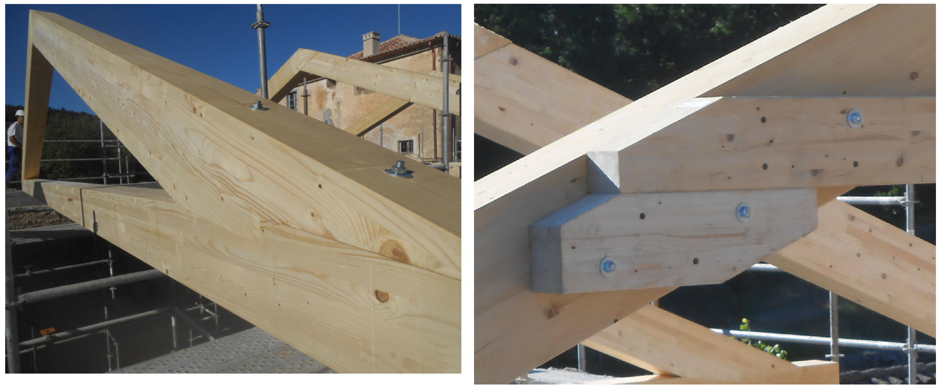
1. Introduction
2. Materials and Methods
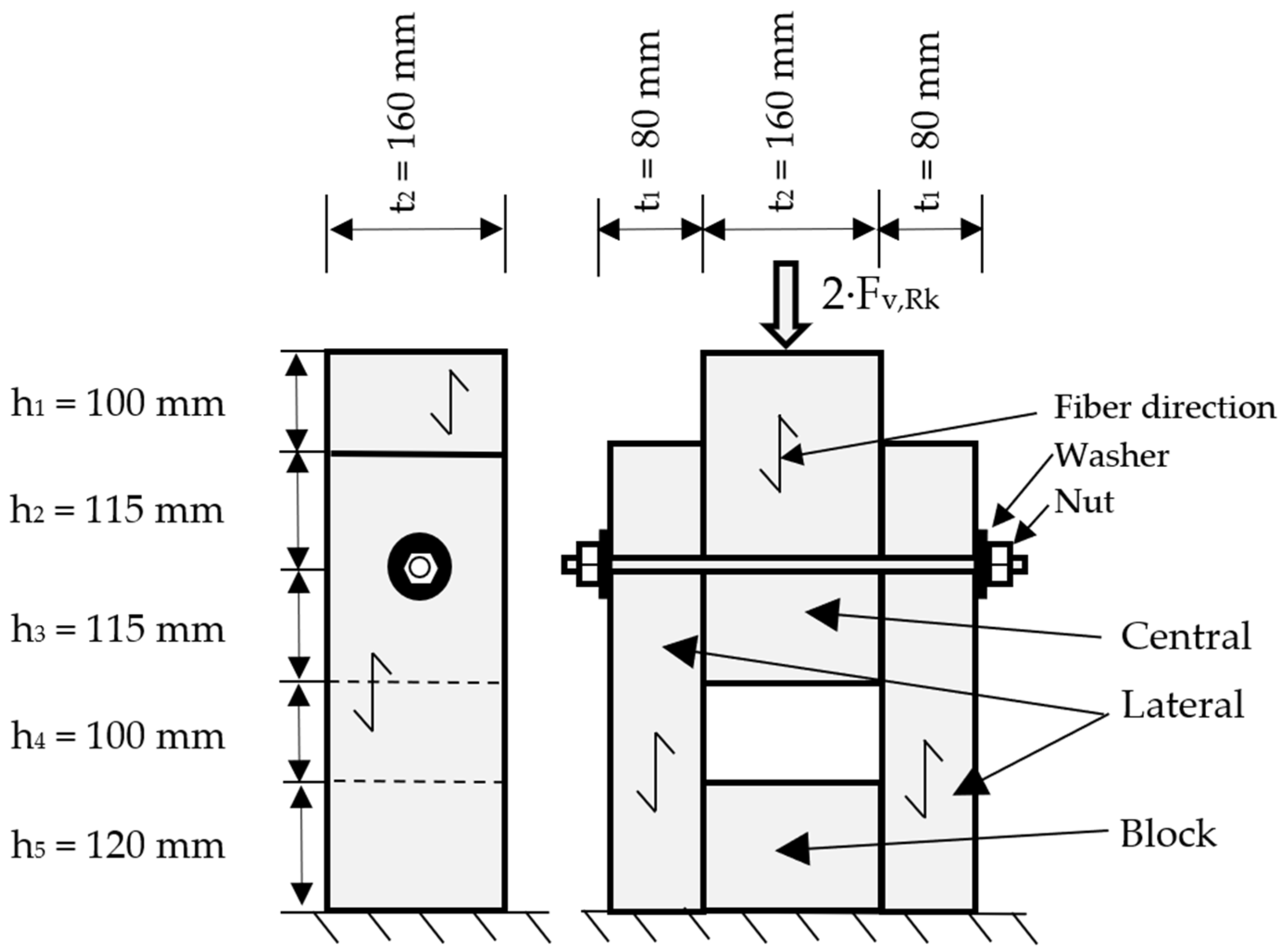
2.1. Geometry of the Configuration
2.2. Equipment for Caractherization Description
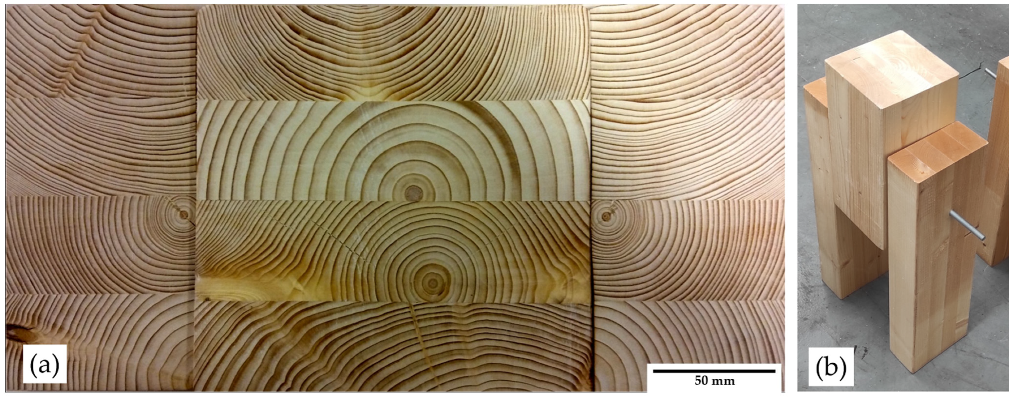
2.3. Timber Description
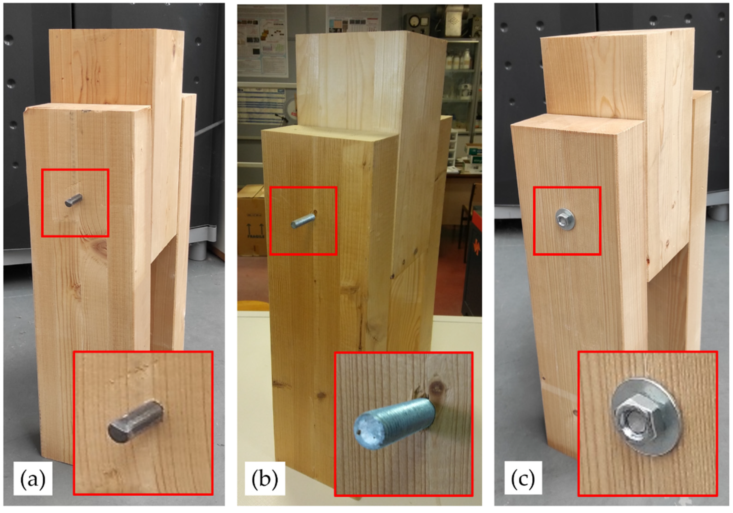
2.4. Characterization of the Connections and Fixings
2.5. Experimental Procedure
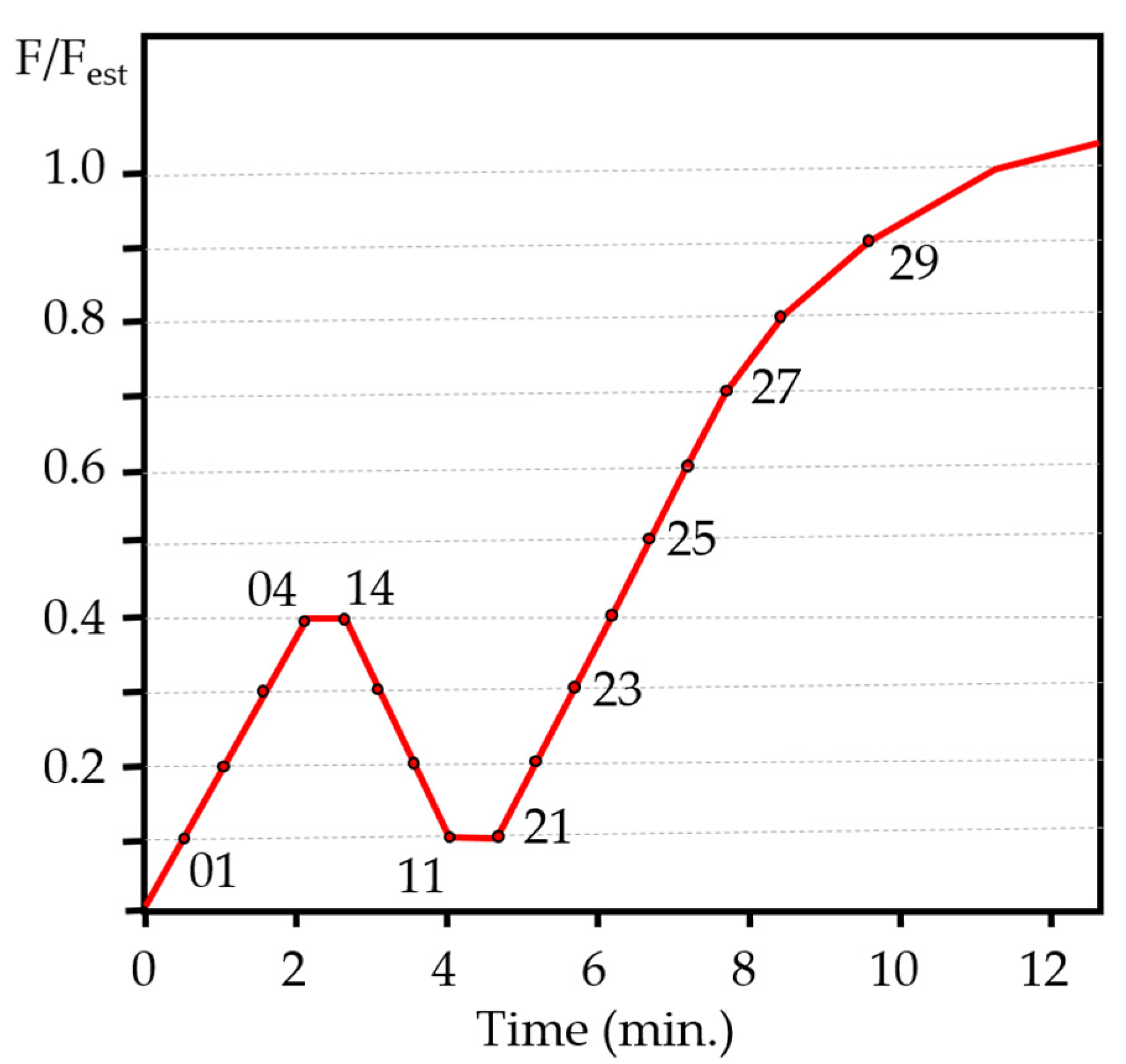
2.6. Development of Test and Load Program
3. Results
3.1. Evolution of the Plastic Moment in the Dowel Hinge with the Load
3.2. Study of the Crush Widths
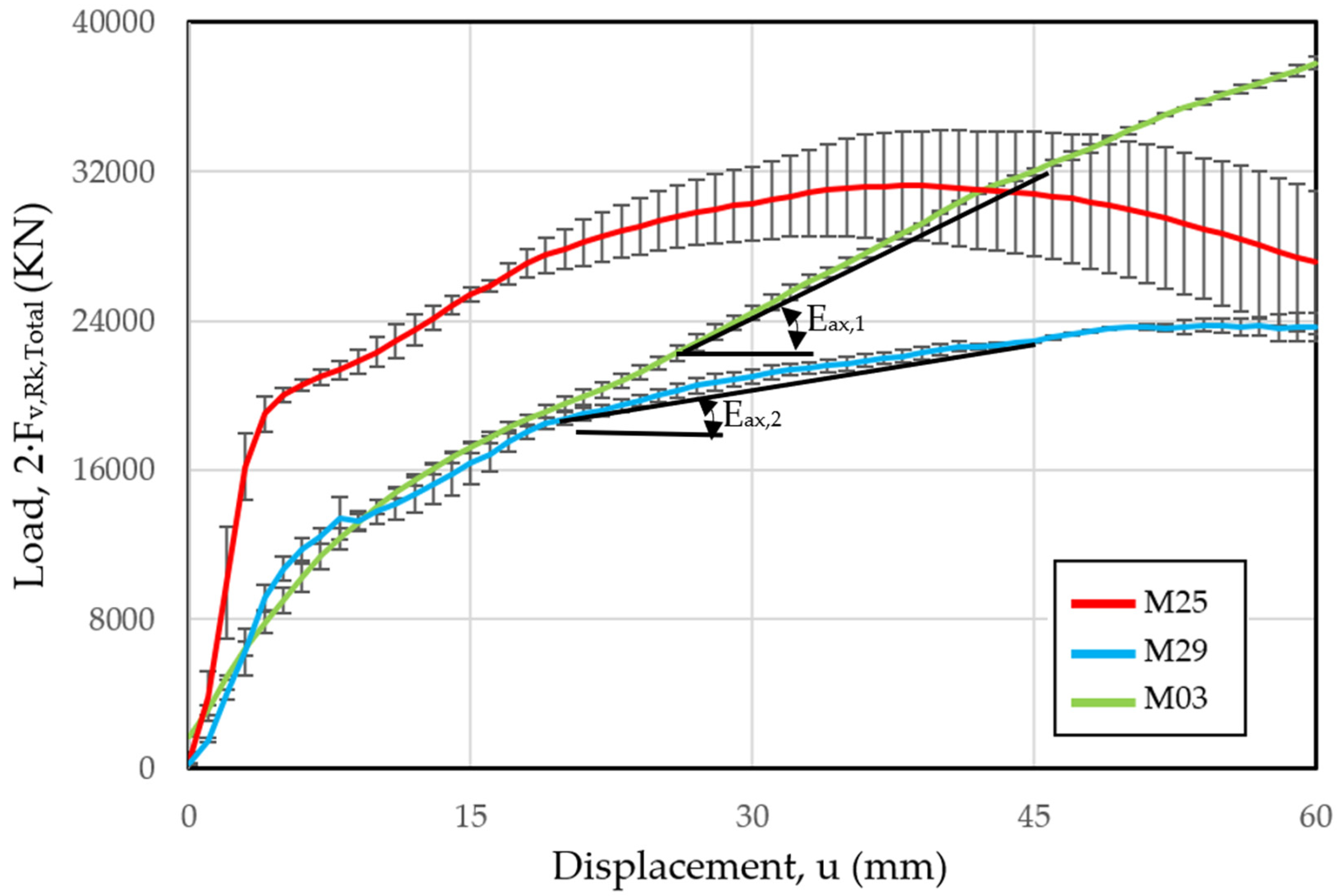
3.3. Load Study vs. Displacement
4. Discussion
5. Conclusions
- Correctly consider the effect of using nut-washer fixings at their ends which generates the so-called rope effect.
- Limit the possibilities of failure in the timber region under the nut compression.
- Consider its influence depending on its origin (the friction between the dowel and timber hole surfaces, the insertion of the dowel thread in the wood or the presence of the nut-washer fixings at their ends).
- Allow the superposition of its effects with the other resistance mechanisms present in the connection.
- The initial hole diameter
- The minimum diameter (or net section) of the dowel if a threaded one is used
- The final diameter, once the assembly has been made, taking into account clearances, and/or the timber crushing under the dowel, especially when the diameter of the dowel is bigger than the hole in which it is inserted.
- A constant limit value of the load capacity which is indicated in the standards and
- A constant limit value of the displacement (u = 15 mm) in the joint to be used in the tests.
- The displacement limits of the joint in relationship with the joint size, because a constant displacement limit (u = 15 mm) may be excessive in small-dimension joints and, on the contrary, very restrictive in large joints
- The rope effect resistive capacity increments, especially in joints using nut-washer fixings.
Author Contributions
Funding
Institutional Review Board Statement
Informed Consent Statement
Acknowledgments
Conflicts of Interest
Nomenclature
| Lower case symbols and abbreviations | |
| a1 (2) | width external crushing in the interaction between timber and dowel (mm) |
| b1(2) | internal crush width on timber side (middle) piece (mm) |
| d | nail diameter (mm). |
| dh | nail head diameter (mm). |
| dint | net diameter (mm) |
| fax,k (m) | characteristic (mean) value of the tear-off resistance in the nose piece (N/mm2) |
| fh,1 (2),k (m) | characteristic (mean) resistance to crushing for the side (middle) piece of timber (N/mm2) |
| fhead,k | characteristic value of nail head punching resistance (N/mm2) |
| fm,g,k | bending strength of timber (N/mm2) |
| fc,0 (90),g,k | compressive strength parallel (perpendicular) to grain of timber (N/mm2) |
| ft,0 (90),g,k | tensile strength parallel (perpendicular) to grain of timber (N/mm2) |
| fv,g,k | shear strength parallel to grain of the timber (N/mm2) |
| fy,k | yield strength of steel (N/mm2) |
| fu,k | ultimate strength of steel (N/mm2) |
| u | displacement (mm) |
| tpen | penetration length in the nose piece or the length of the corrugated portion in the nose piece (mm) |
| th | thickness at the head of the piece (mm) |
| t1 (2) | thickness of timber side (middle) piece (mm) |
| th | thickness at the head of the piece (mm) |
| Uppercase symbols and abbreviations | |
| E0 (90),g,m | modulus of elasticity mean parallel (perpendicular) to fibers of timber (N/mm2) |
| Eax | slope in the plastic behavior of the hinge (N/mm) |
| Es | modulus of elasticity of steel (GPa) |
| Gr,g,m | shear mean modulus of timber (N/mm2) |
| Fest | estimated load (KN) |
| My,Rk | plastic moment (KN·mm) |
| Fax,Rk (m) | characteristic (mean) load capacity upon removal of the fixing element (KN) |
| Greek symbols | |
| ρg,k, (m) | characteristic (mean) density of timber (kg/mm3) |
| ξ | plasticity index of the dowel |
| ν | poisson’s ratio of steel |
| β | crush strength ratio (fh,2,k/fh,1,k) |
| θ | hinge joint angle (°) |
| ΔL | length of embedment of washer in wood (mm) |
Appendix A


References
- Lathuillière, D.; Bléron, L.; Descamps, T.; Bocquet, J.F. Reinforcement of dowel type connections. Constr. Build. Mater. 2015, 97, 48–54. [Google Scholar] [CrossRef]
- Jockwer, R.; Fink, G.; Köhler, J. Assessment of the failure behaviour and reliability of timber connections with multiple dowel-type fasteners. Eng. Struct. 2018, 172, 76–84. [Google Scholar] [CrossRef]
- Ringhofer, A.; Brandner, R.; Blaß, H.J. Cross laminated timber (CLT): Design approaches for dowel-type fasteners and connections. Eng. Struct. 2018, 171, 849–861. [Google Scholar] [CrossRef]
- Argüelles, R.; Arriaga, F.; Martínez, J. Estructuras de Madera. Diseño y Cálculo; AITIM: Madrid, Spain, 2003. [Google Scholar]
- Rodd, P.D.; Leijten, A.J.M. High-performance dowel-type joints for timber structures. Prog. Struct. Eng. Mater. April 2003, 5, 77–89. [Google Scholar] [CrossRef]
- Labèrnia, C. Guía de Construir con Madera: Documento de Aplicación del CTE; Confemadera: Madrid, Spain, 2010. [Google Scholar]
- CEN/Technical Committee 250. EN 1995-1-1 2004/AC:2006 Eurocode 5: Design of Timber Structures. Part 1-1: General–Common Rules and Rules for Buildings; European Committee for Standardization: Bruxelles, Belgium, 2006. [Google Scholar]
- Stepinac, M.; Cabrero, J.M.; Ranasinghe, K.; Kleiber, M. Proposal for reorganization of the connections chapter of Eurocode 5. Eng. Struct. 2018, 170, 135–145. [Google Scholar] [CrossRef]
- Gečys, T.; Bader, T.K.; Olsson, A.; Kajėnas, S. Influence of the rope effect on the slip curve of laterally loaded, nailed and screwed timber-to-timber connections. Constr. Build. Mater. 2019, 228, 116702. [Google Scholar] [CrossRef]
- Liu, Y.; Yao, Z.; Wang, F.; Huang, H.; Que, Z. Effect of arrangement distances on stiffness of shear-tension mode in timber-to-timber connections with inclined screws. Constr. Build. Mater. 2022, 314, 125592. [Google Scholar] [CrossRef]
- Solarino, F.; Giresini, L.; Chang, W.-S.; Huang, H. Experimental Tests on a Dowel-Type Timber Connection and Validation of Numerical Models. Buildings 2017, 7, 16. [Google Scholar] [CrossRef] [Green Version]
- Polastri, A.; Tomasi, R.; Piazza, M.; Smith, I. Moment resisting dowelled joints in timber structures: Mechanical behaviour under cyclic tests. Ing. Sismica 2013, 30, 72–81. [Google Scholar]
- He, M.; Tao, D.; Li, Z.; Li, M. Mechanical behavior of dowel-type joints made of wood scrimber composite. Materials 2016, 9, 581. [Google Scholar] [CrossRef] [PubMed] [Green Version]
- Johanides, M.; Mikolasek, D.; Lokaj, A.; Mynarcik, P.; Marcalikova, Z.; Sucharda, O. Rotational Stiffness and Carrying Capacity of Timber Frame Corners with Dowel Type Connections. Materials 2021, 14, 7429. [Google Scholar] [CrossRef] [PubMed]
- Chen, Z.; Niu, X.; Liu, J.; Khan, K. Experimental study of thin-walled steel-timber single-shear connection with a self-tapping screw. Structures 2021, 34, 4389–4405. [Google Scholar] [CrossRef]
- Johansen, K.W. Theory of Timber Connections. IABSE Int. Assoc. Bridg. Struct. Eng. 1949, 9, 249–262. [Google Scholar]
- Hilson, B.O. Joints with dowel-type fasteners. Timber Eng. STEP 1 Cent. 1995, 3, 7. [Google Scholar]
- Aune, P.; Patton-Mallory, M. Lateral Load-Bearing Capacity of Nailed Joints Based on the Yield Theory: Theoretical Development; FPL469 Forest Products Laboratory. US Department of Agriculture: Washington, DC, USA, 1986. [Google Scholar]
- Yurrita, M.; Cabrero, J.M. On the need of distinguishing ductile and brittle failure modes in timber connections with dowel-type fasteners. Eng. Struct. 2021, 242, 112496. [Google Scholar] [CrossRef]
- Pavković, K.; Stepinac, M.; Rajčić, V. Brittle failure modes in reinforced and non-reinforced timber joint with large diameter fastener loaded parallel to grain. Eng. Struct. 2020, 222, 111104. [Google Scholar] [CrossRef]
- Guan, Z.W.; Rodd, P.D. Hollow steel dowels-a new application in semi-rigid timber connections. Eng. Struct. 2001, 23, 110–119. [Google Scholar] [CrossRef]
- López, I.A. El nuevo enfoque en los ensayos mecánicos de la madera aserrada para uso estructural en la normativa europea. Madera Bosques 2016, 8, 3–16. [Google Scholar] [CrossRef] [Green Version]
- Larsson, G.; Serrano, E.; Gustafsson, P.J.; Danielsson, H. Dowel design of the shear plate dowel joint. Eng. Struct. 2020, 209, 110296. [Google Scholar] [CrossRef]
- European Committee for Standardization. CEN/TC 175, EN 13183-2:2002/AC:2003 Moisture Content of a Piece of Sawn Timber—Part 2: Estimation by Electrical Resistance Method; European Committee for Standardization: Bruxelles, Belgium, 2003. [Google Scholar]
- CEN/Technical Comittee 56. EN 14080: Timber Structures—Glued Laminated Timber and Glued Solid Timber—Requirements; European Committee for Standardization: Bruxelles, Belgium, 2017; p. 120. [Google Scholar]
- Ramage, M.H.; Burridge, H.; Busse-Wicher, M.; Fereday, G.; Reynolds, T.; Shah, D.U.; Wu, G.; Yu, L.; Fleming, P.; Densley-Tingley, D.; et al. The wood from the trees: The use of timber in construction. Renew. Sustain. Energy Rev. 2017, 68, 333–359. [Google Scholar] [CrossRef]
- AEN/TC 56, EN 56544: Visual Grading for Structural Sawn Timber. Coniferous Timber; European Committee for Standardization: Bruxelles, Belgium, 2011. [Google Scholar]
- ISO/Technical Comittee 164/SC. Metallic Materials—Tensile Testing—Part 3: Method of Test at Low Temperature EN ISO 6892-3:2015; International Organization for Standardization: Geneva, Switzerland, 2015. [Google Scholar]
- CEN/Technical Committee 124. Timber Structures. Joints Made with Mechanical Fasteners. General Principles for the Determination of Strength and Deformation Characteristics EN 26891:1991; European Committee for Standardization: Bruxelles, Belgium, 1991. [Google Scholar]
- CEN/Technical Committee 56. Timber Structures—Structural Timber and Glued Laminated Timber—Determination of Some Physical and Mechanical Properties UNE-EN 408:2011+A1:2012; European Committee for Standardization: Bruxelles, Belgium, 2011. [Google Scholar]
- Blaß, H.J.; Bienhaus, A.; Krämer, V. Effective bending capacity of dowel-type fasteners. Proc. Int. RILEM Symp. Joints Timber Struct. 2001, 22, 71–88. [Google Scholar]
- Domínguez, M.; Fueyo, J.G.; Cabezas, J.A. Accounting of the thread embedment in timber structures dowel-type joints. Load-slip relationship. Proc. Inst. Mech. Eng. Part C J. Mech. Eng. Sci. 2017, 231, 150–160. [Google Scholar] [CrossRef]
- Budynas, R.G.; Nisbett, J.K. Shigley’s Mechanical Engineering Design; McGraw Hill: New York, NY, USA, 2008. [Google Scholar]
- Fueyo, J.G.; Cabezas, J.A.; Domínguez, M.; Antón, N.; Villarino, A. Energy distribution in dowel-type joints in timber structures when using expansive kits. Forests 2021, 12, 1200. [Google Scholar] [CrossRef]
- Zhang, C.; Guo, H.; Jung, K.; Harris, R.; Chang, W.S. Using self-tapping screw to reinforce dowel-type connection in a timber portal frame. Eng. Struct. 2019, 178, 656–664. [Google Scholar] [CrossRef]
- Nuere, E. Madera, en restauración y rehabilitación. Inf. Construcción 2007, 59, 123–130. [Google Scholar]
- Fernández, J.L. La estructura de la cubierta de la pieza de recepción del Centro Especial de Empleo Aspanias. Morales del Vino, Zamora. Inf. Construcción 2007, 59, 62–67. [Google Scholar]


| Properties | Symbol | Value |
|---|---|---|
| Bending strength (N/mm2) | fm,g,k | 24 |
| Tensile strength parallel to grain (N/mm2) | ft,0,g,k | 19.2 |
| Tensile strength perpendicular to grain (N/mm2) | ft,90,g,k | 0.5 |
| Compressive strength parallel to grain (N/mm2) | fc,0,g,k | 24 |
| Compressive strength perpendicular to grain (N/mm2) | fc,90,g,k | 2.5 |
| Shear strength parallel to grain (N/mm2) | fv,g,k | 3.5 |
| Modulus of Elasticity parallel to grain (N/mm2) | E0,g,m | 11,500 |
| Modulus of Elasticity perpendicular to grain (N/mm2) | E90,g,m | 300 |
| Shear modulus (N/mm2) | Gr,g,m | 65 |
| Characteristic density (kg/mm3) | ρg,k | 385 |
| Mean density (kg/mm3) | ρg,m | 420 |
| Eurocode 5 | Experimental | Safe Factor | |||||
|---|---|---|---|---|---|---|---|
| Serie | 2·Fv,Rk,EC5 (N) | 2·Fv,R,m,EC5 (N) | Fax,Rk (N) | Test Sample | 2·Fv,R,Exp (N) (u = 15mm) | Fv,Rk,EC5 /Fv,R,Exp (%) | Fv,R,m,EC5 /Fv,R,Exp (%) |
| M25 | 8714.2 | 9274.4 | 0 | P134 P135 P136 | 25,173.5 25,116.7 25,968.2 | 288.9 288.2 298.0 | 271.4 270.8 280.0 |
| M29 | 5767.2 | 6137.9 | 0 | P056 P059 P060 | 15,022.7 16,517.4 17,577.0 | 260.5 286.4 304.8 | 244.8 269.1 286.4 |
| M03 | 5779.4 | 6150.1 | 6.1 | P001 P014 P026 | 16,966.5 16,963.5 17,524.9 | 293.6 293.5 303.2 | 275.9 275.8 285.0 |
Publisher’s Note: MDPI stays neutral with regard to jurisdictional claims in published maps and institutional affiliations. |
© 2021 by the authors. Licensee MDPI, Basel, Switzerland. This article is an open access article distributed under the terms and conditions of the Creative Commons Attribution (CC BY) license (https://creativecommons.org/licenses/by/4.0/).
Share and Cite
Domínguez, M.; Fueyo, J.G.; Villarino, A.; Anton, N. Structural Timber Connections with Dowel-Type Fasteners and Nut-Washer Fixings: Mechanical Characterization and Contribution to the Rope Effect. Materials 2022, 15, 242. https://doi.org/10.3390/ma15010242
Domínguez M, Fueyo JG, Villarino A, Anton N. Structural Timber Connections with Dowel-Type Fasteners and Nut-Washer Fixings: Mechanical Characterization and Contribution to the Rope Effect. Materials. 2022; 15(1):242. https://doi.org/10.3390/ma15010242
Chicago/Turabian StyleDomínguez, Manuel, Jose G. Fueyo, Alberto Villarino, and Natividad Anton. 2022. "Structural Timber Connections with Dowel-Type Fasteners and Nut-Washer Fixings: Mechanical Characterization and Contribution to the Rope Effect" Materials 15, no. 1: 242. https://doi.org/10.3390/ma15010242