
Fabric-Reinforced Cementitious Matrix (FRCM) Carbon Yarns with Different Surface Treatments Embedded in a Cementitious Mortar: Mechanical and Durability Studies


Abstract
:1. Introduction
2. Materials and Methods
2.1. Materials
2.2. Surface Treatments
2.3. Tensile and Pull-Out Tests
2.4. Aging Conditioning Protocol
2.5. SEM and EDX Analysis
3. Experimental Results
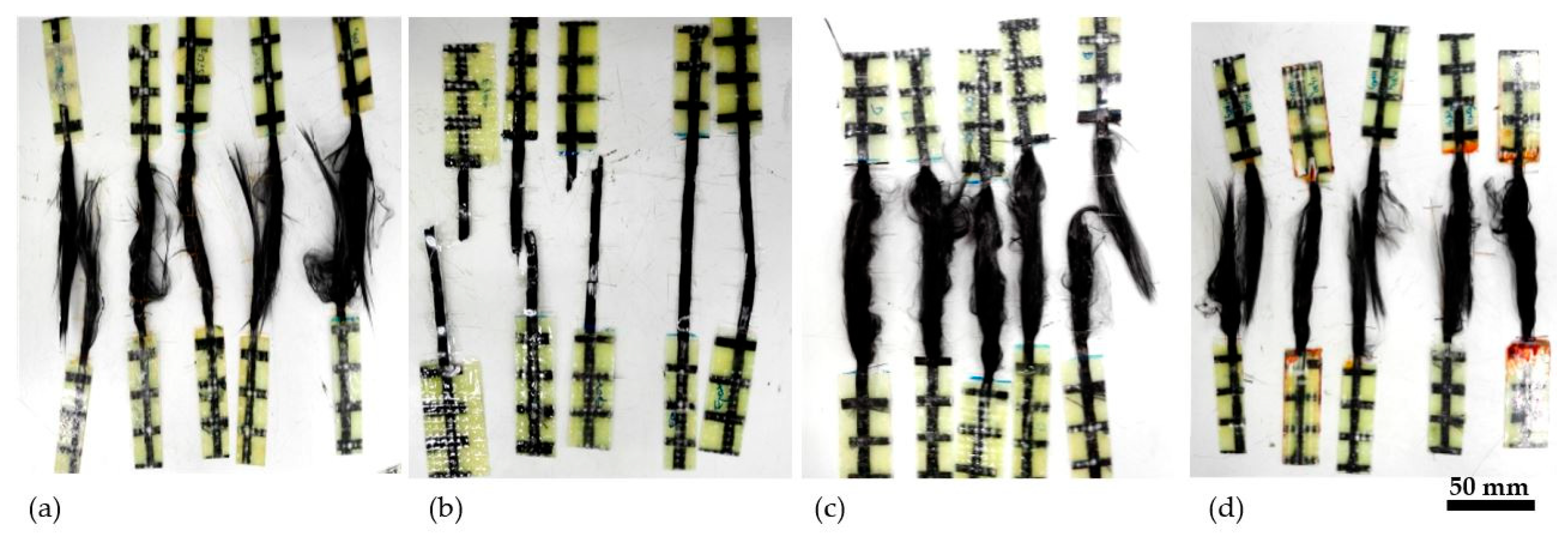
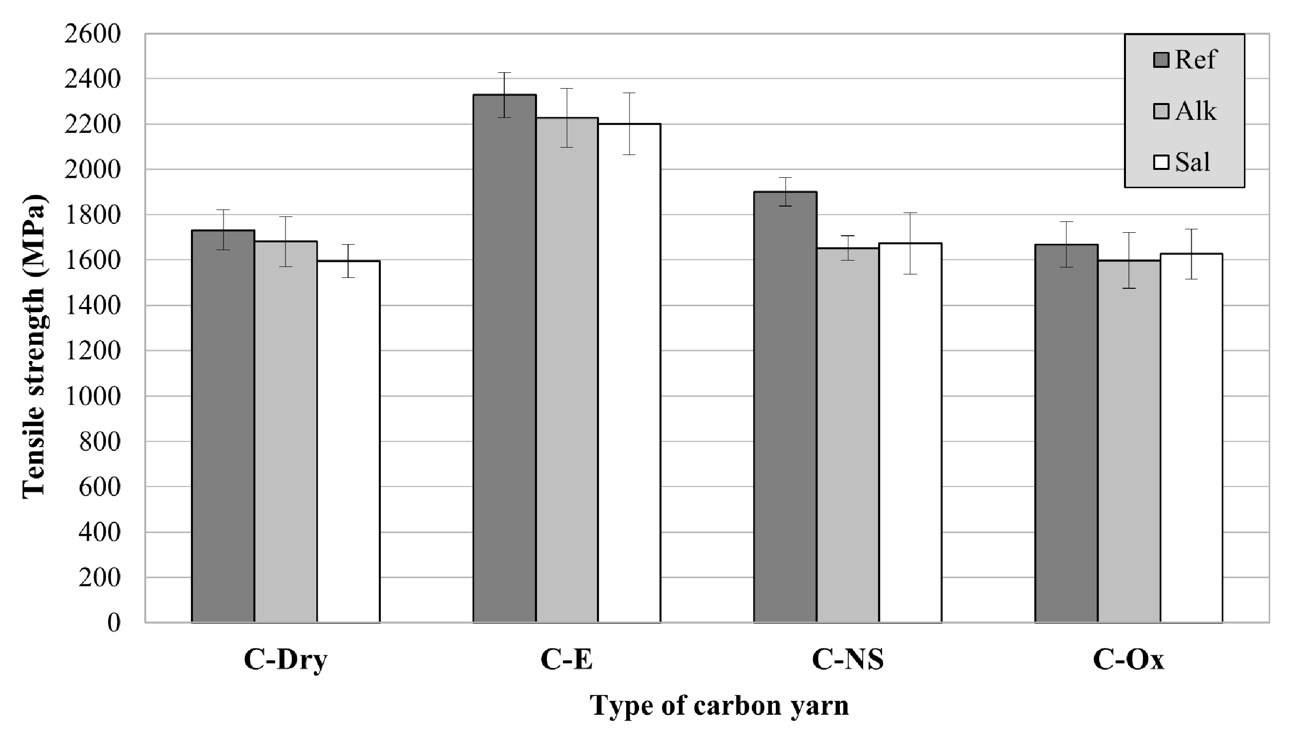
3.1. Tensile Tests
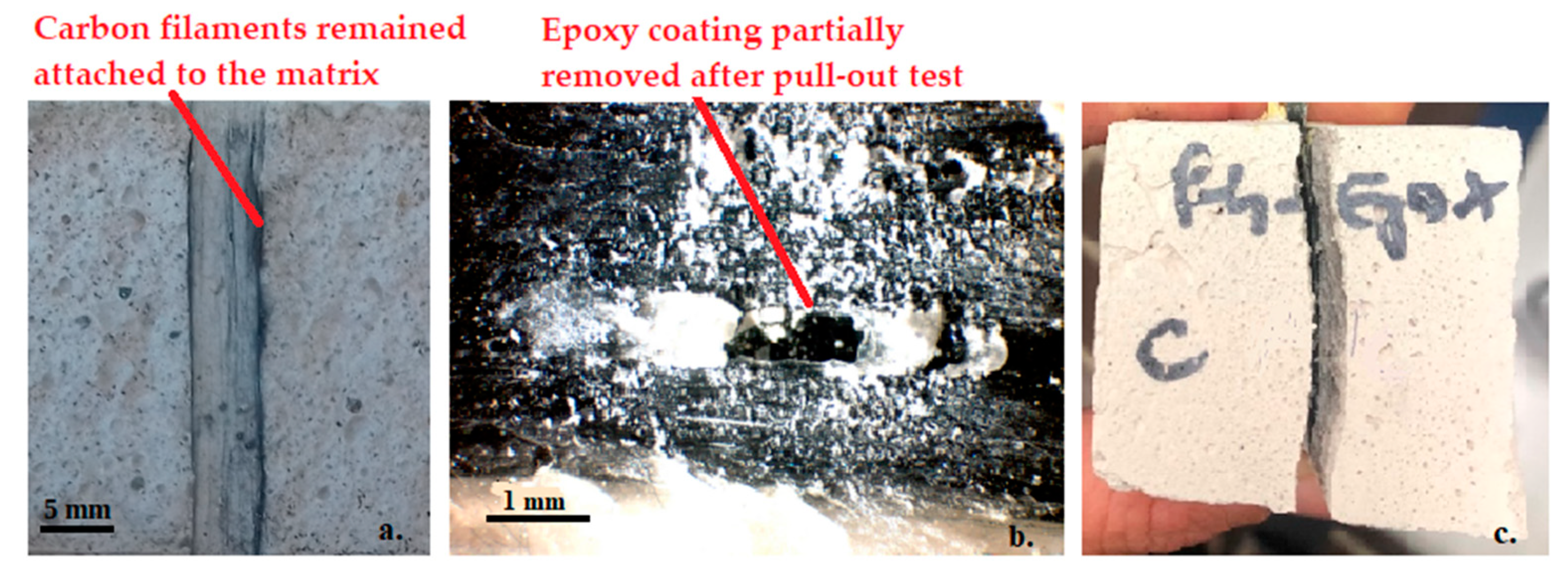
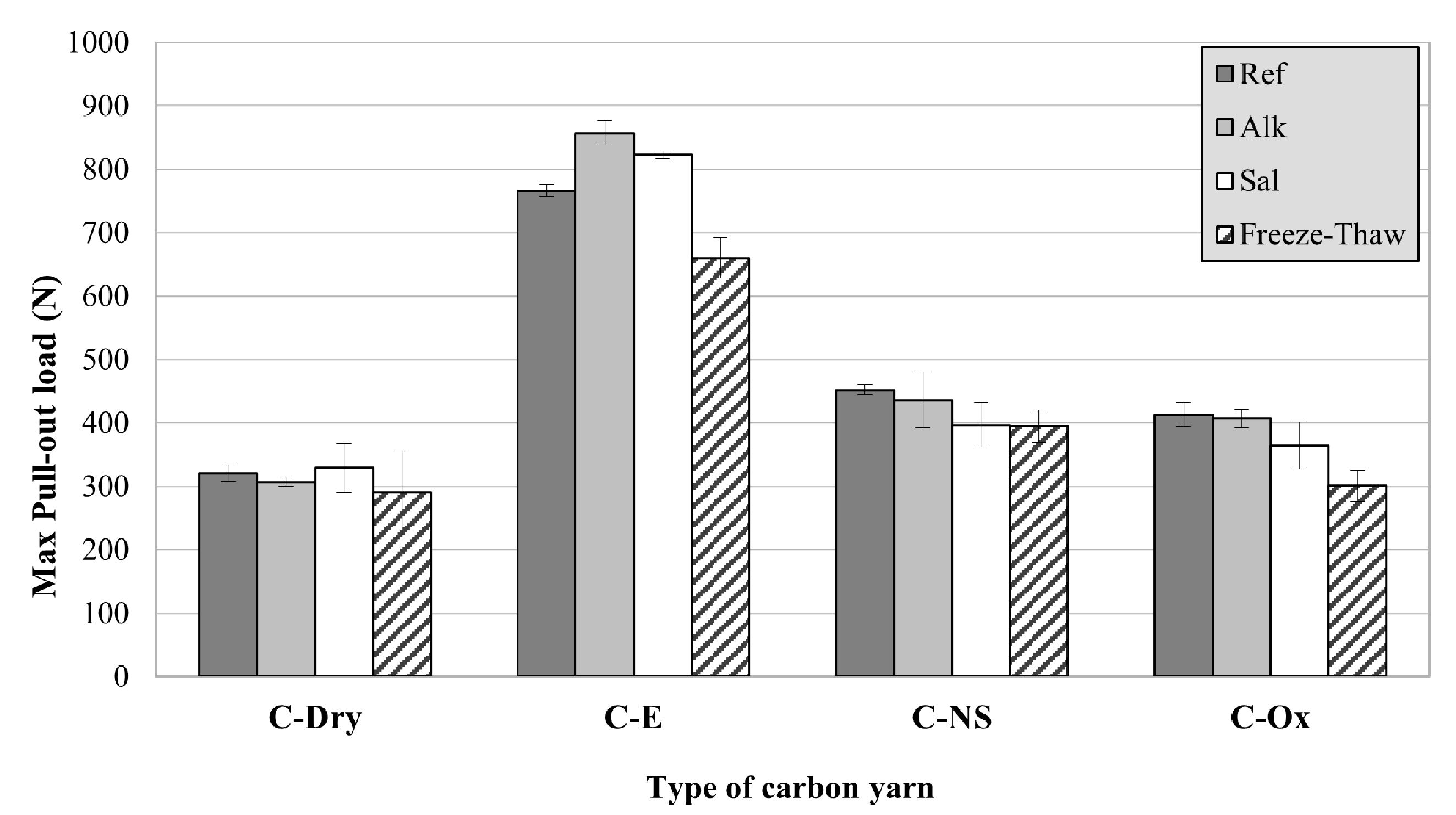
3.2. Pull-Out Tests
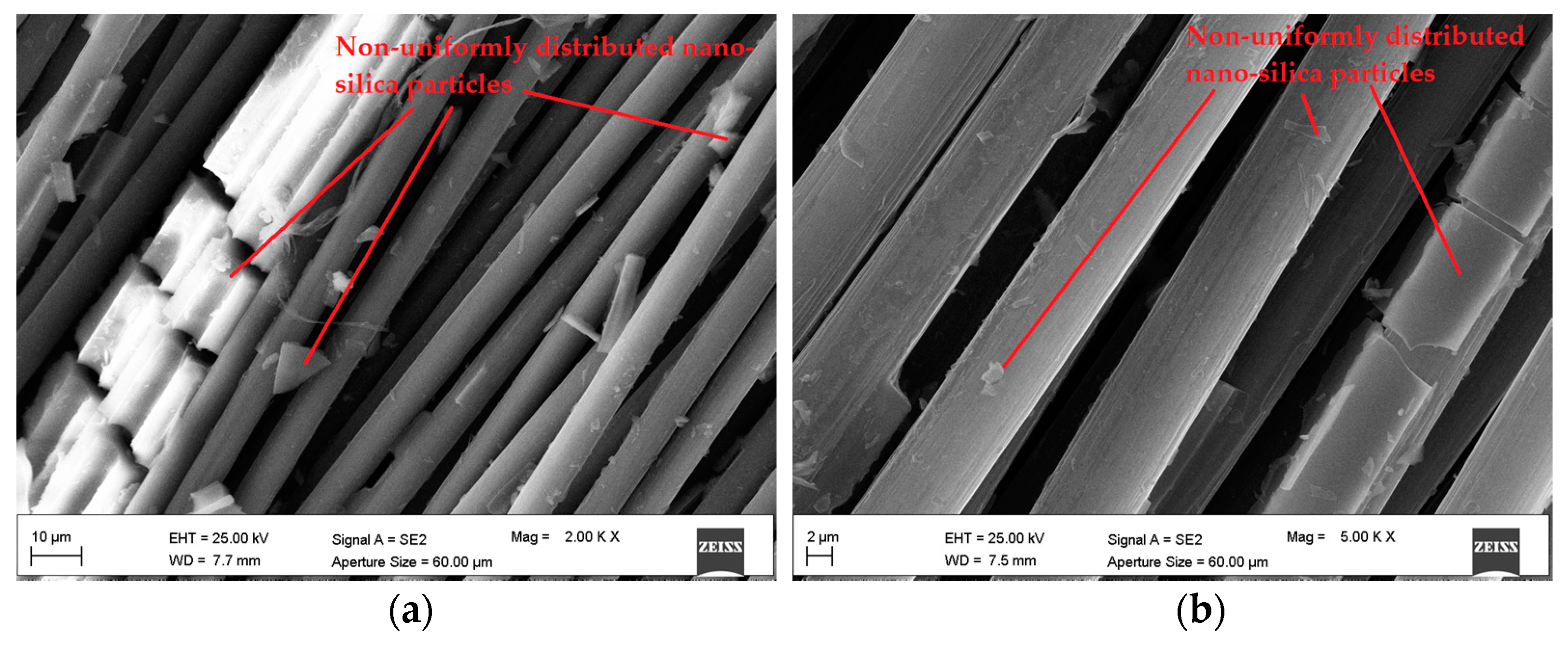
3.3. EDX and SEM Analysis
4. Conclusions
- Pre-impregnation of multifilament carbon yarns with epoxy proved to be the most effective treatment, capable of increasing both the yarn tensile strength and the bond with the cement-based mortar. Epoxy was able to increase the carbon yarn tensile strength by about 34% and the pull-out load of about 138%. These effects, as well known from the literature, can be attributed to the ability of the low-viscosity epoxy to penetrate between single filaments of the yarn, thus guaranteeing a more homogeneous stress distribution through the yarn cross-section. However, it must be remembered that the use of organic polymers remains a weakness with regards to the mechanical behavior of the composite when exposed to high temperatures.
- The nano-silica coating was less effective than epoxy, but still able to increase the yarn tensile strength by 10% and the pull-out load by about 40%. However, the effectiveness of this treatment can be improved by optimizing the manufacturing process, to ensure a more homogeneous distribution of the particles on the yarn surface.
- The oxidation of carbon fibers with HNO3/H2SO4 solution seems not to substantially modify the mechanical properties of the carbon yarns. SEM analyses did not show significant changes in the surface of the carbon filaments after the oxidation process. However, this treatment was able to increase the pull-out load by about 28%. Further analyses are certainly needed to better investigate this aspect.
- Artificial aging in saline and alkaline environments caused only a slight reduction of the yarn tensile strength, which was always lower than 13%, regardless of the type of surface treatment applied.
- Pull-out tests carried out after exposure of the specimens in saline and alkaline environments showed no significant decrease in mechanical performance. Carbon yarns with epoxy impregnation showed the highest load values. Exposure to freeze-thaw cycles caused the greatest reduction in the pull-out load (between −10% and −27%), probably due to internal damage of the inorganic matrix (which in some cases broke in half during the test), rather than to deterioration of the carbon yarn.
Author Contributions
Funding
Institutional Review Board Statement
Informed Consent Statement
Data Availability Statement
Conflicts of Interest
References
- Nanni, A. A New Tool for Concrete and Masonry Repair. Concr. Int. 2012, 34, 1–7. [Google Scholar]
- Awani, O.; El-Maaddawy, T.; Ismail, N. Fabric-reinforced cementitious matrix: A promising strengthening technique for concrete structures. Constr. Build. Mater. 2017, 132, 94–111. [Google Scholar] [CrossRef]
- Papanicolaou, C.; Triantafillou, T.; Lekka, M. Externally bonded grids as strengthening and seismic retrofitting materials of masonry panels. Constr. Build. Mater. 2011, 25, 504–514. [Google Scholar] [CrossRef]
- Donnini, J.; Maracchini, G.; Lenci, S.; Corinaldesi, V.; Quagliarini, E. TRM reinforced tuff and fired clay brick masonry: Experimental and analytical investigation on their in-plane and out-of-plane behavior. Constr. Build. Mater. 2021, 272, 121643. [Google Scholar] [CrossRef]
- D’Ambrisi, A.; Feo, L.; Focacci, F. Experimental and analytical investigation on bond between Carbon-FRCM materials and masonry. Compos. Part B Eng. 2013, 46, 15–20. [Google Scholar] [CrossRef]
- Carozzi, F.G.; Bellini, A.; D’Antino, T.; De Felice, G.; Focacci, F.; Hojdys, Ł.; Laghi, L.; Lanoye, E.; Micelli, F.; Panizza, M.; et al. Experimental investigation of tensile and bond properties of Carbon-FRCM composites for strengthening masonry elements. Compos. Part B Eng. 2017, 128, 100–119. [Google Scholar] [CrossRef]
- Donnini, J.; Lancioni, G.; Corinaldesi, V. Failure modes in FRCM systems with dry and pre-impregnated carbon yarns: Experiments and modeling. Compos. Part B Eng. 2018, 140, 57–67. [Google Scholar] [CrossRef]
- Tiwari, S.; Bijwe, J. Surface Treatment of Carbon Fibers—A Review. Procedia Technol. 2014, 14, 505–512. [Google Scholar] [CrossRef] [Green Version]
- Alatawna, A.; Sripada, R.; Nahum, L.; Birenboimi, M.; Regev, O.; Peled, A. Textile-cement bond enhancement: Sprinkle some hydrophilic powder. Cem. Concr. Compos. 2021, 120, 104031. [Google Scholar] [CrossRef]
- Jang, J.; Yang, H. Effect of surface treatment on the performance improvement of carbon fiber/polybenzoxazine composites. J. Mater. Sci. 2000, 35, 2297–2303. [Google Scholar] [CrossRef]
- Schleser, M.; Walk-Lauffer, B.; Raupach, M.; Dilthey, U. Application of Polymers to Textile-Reinforced Concrete. J. Mater. Civ. Eng. 2006, 18, 670–676. [Google Scholar] [CrossRef]
- Mader, E.; Plonka, R.; Schiekel, M.; Hempel, R. Coatings on Alkali-Resistant Glass Fibres for the Improvement of Concrete. J. Ind. Text. 2004, 33, 191–207. [Google Scholar] [CrossRef]
- Messori, M.; Nobili, A.; Signorini, C.; Sola, A. Mechanical performance of epoxy coated AR-glass fabric Textile Reinforced Mortar: Influence of coating thickness and formulation. Compos. Part B Eng. 2018, 149, 135–143. [Google Scholar] [CrossRef] [Green Version]
- Tayeh, B.A.; El Dada, Z.M.; Shihada, S.; Yusuf, M.O. Pull-out behavior of post installed rebar connections using chemical adhesives and cement based binders. J. King Saud Univ. Eng. Sci. 2019, 31, 332–339. [Google Scholar] [CrossRef]
- Bompadre, F.; Donnini, J. Surface Modification of Glass Textile for the Reinforcement of a Cement-Based Composite: A Review. Appl. Sci. 2021, 11, 2028. [Google Scholar] [CrossRef]
- Bompadre, F.; Scheffler, C.; Utech, T.; Donnini, J. Polymeric Coatings for AR-Glass Fibers in Cement-Based Matrices: Effect of Nanoclay on the Fiber-Matrix Interaction. Appl. Sci. 2021, 11, 5484. [Google Scholar] [CrossRef]
- Donnini, J.; Corinaldesi, V.; Nanni, A. Mechanical properties of FRCM using carbon fabrics with different coating treatments. Compos. Part B Eng. 2016, 88, 220–228. [Google Scholar] [CrossRef]
- Signorini, C.; Nobili, A.; Sola, A.; Messori, M. Designing epoxy viscosity for optimal mechanical performance of coated Glass Textile Reinforced Mortar (GTRM) composites. Constr. Build. Mater. 2020, 233, 117325. [Google Scholar] [CrossRef]
- Banholzer, B.; Tanja, B.; Brameshuber, W. Material and bonding characteristics for dimensioning and modelling of textile reinforced concrete (TRC) elements. Mater. Struct. 2006, 39, 749–763. [Google Scholar] [CrossRef]
- Bisby, L. Fire Resistance of Textile Fiber Composites Used in Civil Engineering. Text. In Textile Fibre Composites in Civil Engineering; Woodhead Publishing: Cambridge, UK, 2016. [Google Scholar] [CrossRef]
- Donnini, J.; De Caso y Basalo, F.; Corinaldesi, V.; Lancioni, G.; Nanni, A. Fabric-reinforced cementitious matrix behavior at high-temperature: Experimental and numerical results. Compos. Part B Eng. 2017, 108, 108–121. [Google Scholar] [CrossRef] [Green Version]
- Trapko, T. The effect of high temperature on the performance of CFRP and FRCM confined concrete elements. Compos. Part B Eng. 2013, 54, 138–145. [Google Scholar] [CrossRef]
- Di Maida, P.; Radi, E.; Sciancalepore, C.; Bondioli, F. Pullout behavior of polypropylene macro-synthetic fibers treated with nano-silica. Constr. Build. Mater. 2015, 82, 39–44. [Google Scholar] [CrossRef] [Green Version]
- Nadiv, R.; Peled, A.; Mechtcherine, V.; Hempel, S.; Schroefl, C. Micro- and nanoparticle mineral coating for enhanced properties of carbon multifilament yarn cement-based composites. Compos. Part B Eng. 2017, 111, 179–189. [Google Scholar] [CrossRef]
- Schneider, K.; Michel, A.; Liebscher, M.; Terreri, L.; Hempel, S.; Mechtcherine, V. Mineral-impregnated carbon fibre reinforcement for high temperature resistance of thin-walled concrete structures. Cem. Concr. Compos. 2019, 97, 68–77. [Google Scholar] [CrossRef]
- Lu, M.; Xiao, H.; Liu, M.; Li, X.; Li, H.; Sun, L. Improved interfacial strength of SiO2 coated carbon fiber in cement matrix. Cem. Concr. Compos. 2018, 91, 21–28. [Google Scholar] [CrossRef]
- Signorini, C.; Sola, A.; Nobili, A.; Siligardi, C. Lime-cement textile reinforced mortar (TRM) with modified interphase. J. Appl. Biomater. Funct. Mater. 2019, 17, 2280800019827823. [Google Scholar] [CrossRef] [Green Version]
- Li, H.; Zhao, D.; Liebscher, M.; Yin, B.; Yang, J.; Kaliske, M.; Mechtcherine, V. An experimental and numerical study on the age depended bond-slip behavior between nano-silica modified carbon fibers and cementitious matrices. Cem. Concr. Compos. 2022, 128, 104416. [Google Scholar] [CrossRef]
- Signorini, C.; Nobili, A.; González, E.C.; Siligardi, C. Silica coating for interphase bond enhancement of carbon and AR-glass Textile Reinforced Mortar (TRM). Compos. Part B Eng. 2018, 141, 191–202. [Google Scholar] [CrossRef] [Green Version]
- Franzoni, E.; Gentilini, C.; Santandrea, M.; Carloni, C. Effects of rising damp and salt crystallization cycles in FRCM-masonry interfacial debonding: Towards an accelerated laboratory test method. Constr. Build. Mater. 2018, 175, 225–238. [Google Scholar] [CrossRef]
- Franzoni, E.; Santandrea, M.; Gentilini, C.; Fregni, A.; Carloni, C. The role of mortar matrix in the bond behavior and salt crystallization resistance of FRCM applied to masonry. Constr. Build. Mater. 2019, 209, 592–605. [Google Scholar] [CrossRef]
- Donnini, J. Durability of glass FRCM systems: Effects of different environments on mechanical properties. Compos. Part B Eng. 2019, 174, 107047. [Google Scholar] [CrossRef]
- Donnini, J.; Bompadre, F.; Corinaldesi, V. Tensile Behavior of a Glass FRCM System after Different Environmental Exposures. Processes 2020, 8, 1074. [Google Scholar] [CrossRef]
- Micelli, F.; Aiello, M.A. Residual tensile strength of dry and impregnated reinforcement fibres after exposure to alkaline environments. Compos. Part B Eng. 2019, 159, 490–501. [Google Scholar] [CrossRef]
- Micelli, F.; Nanni, A. Durability of FRP rods for concrete structures. Constr. Build. Mater. 2004, 18, 491–503. [Google Scholar] [CrossRef]
- ISO 527-4:2021; Plastics—Determination of Tensile Properties. Part 4: Test Conditions for Isotropic and Orthotropic Fibre-Reinforced Plastic Composites. ISO: Geneva, Switzerland, 2021.
- EN 1015-11:2019; Methods of Test for Mortar for Masonry. Part 11: Determination of Flexural and Compressive Strength of Hardened Mortar. BSI: London, UK, 2019.
- Weichold, O.; Möller, M. A Cement-in-Poly(Vinyl Alcohol) Dispersion for Improved Fibre-Matrix Adhesion in Continuous Glass-Fibre Reinforced Concrete. Adv. Eng. Mater. 2007, 9, 712–715. [Google Scholar] [CrossRef]
- Hoa, L.T.M. Characterization of multi-walled carbon nanotubes functionalized by a mixture of HNO3/H2SO4. Diam. Relat. Mater. 2018, 89, 43–51. [Google Scholar] [CrossRef]
- ISO 10406-1:2015; Fibre-Reinforced Polymer (FRP) Reinforcement of Concrete—Test Methods—Part 1: FRP Bars and Grids. ISO: Geneva, Switzerland, 2015.
- ASTM D1141-98; Standard Practice for the Preparation of Substitute Ocean Water. ASTM Int.: West Conshohocken, PA, USA, 2013.
- Thomason, J.L. Glass fibre sizing: A review. Compos. Part A Appl. Sci. Manuf. 2019, 127, 105619. [Google Scholar] [CrossRef]
- Igarashi, S.; Kawamura, M. Effects of a size in bundled fibers on the interfacial zone between the fibers and the cement paste matrix. Cem. Concr. Res. 1994, 24, 695–703. [Google Scholar] [CrossRef]
- Cohen, Z.; Peled, A. Effect of nanofillers and production methods to control the interfacial characteristics of glass bundles in textile fabric cement-based composites. Compos. Part A Appl. Sci. Manuf. 2012, 43, 962–972. [Google Scholar] [CrossRef]
- D’Antino, T.; Papanicolaou, C. Mechanical characterization of textile reinforced inorganic-matrix composites. Compos. Part B Eng. 2017, 127, 78–91. [Google Scholar] [CrossRef]
- Fu, X.; Lu, W.; Chung, D.D.L. Improving the bond strength between carbon fiber and cement by fiber surface treatment and polymer addition to cement mix. Cem. Concr. Res. 1996, 26, 1007–1012. [Google Scholar] [CrossRef]
- Lavagna, L.; Musso, S.; Ferro, G.; Pavese, M. Cement-based composites containing functionalized carbon fibers. Cem. Concr. Compos. 2018, 88, 165–171. [Google Scholar] [CrossRef]
- Li, H.; Liebscher, M.; Michel, A.; Quade, A.; Foest, R.; Mechtcherine, V. Oxygen plasma modification of carbon fiber rovings for enhanced interaction toward mineral-based impregnation materials and concrete matrices. Constr. Build. Mater. 2021, 273, 121950. [Google Scholar] [CrossRef]
- Li, H.; Liebscher, M.; Ranjbarian, M.; Hempel, S.; Tzounis, L.; Schröfl, C.; Mechtcherine, V. Electrochemical modification of carbon fiber yarns in cementitious pore solution for an enhanced interaction towards concrete matrices. Appl. Surf. Sci. 2019, 487, 52–58. [Google Scholar] [CrossRef]
- Hegger, J.; Will, N.; Bentur, A.; Curbach, M.; Jesse, F.; Mobasher, B.; Peled, A.; Wastiels, J. Mechanical behaviour of textile reinforced concrete. In State-of-the-Art Report of RILEM Technical Committee 201; RILEM Publications SARL: Bagneux, France, 2006; pp. 133–186. [Google Scholar]


| Material | CEM II/B-LL 32.5 R (kg/m3) | CEM II/B-LL 42.5 R (kg/m3) | CaCO3 400 (kg/m3) | CaCO3 600 (kg/m3) | Aerial Lime (kg/m3) | Water (kg/m3) | Compressive Strength (MPa) | Flexural Strength (MPa) |
|---|---|---|---|---|---|---|---|---|
| Cement-based mortar | 82 | 165 | 715 | 205 | 110 | 260 | 17.95 | 5.66 |
| Material | Viscosity (mPa·s) | Tensile Strength (MPa) | Elongation at Break |
|---|---|---|---|
| Elan-tech EC 98N/W52 | 2000–3000 | 0.7–0.9 | 60–80% |
| Environment | Temp | RH | Solution | Exposure Time | N° of Samples (5 for Each Surface Treatment) |
|---|---|---|---|---|---|
| None (Ref) | 20 ± 2 °C | 70% | - | - | 20 tensile tests 20 pull-out tests |
| Saline | 40 ± 2 °C | 100% | 2.45% NaCl + 0.41% Na2SO4 | 1000 h | 20 tensile tests 20 pull-out tests |
| Alkaline | 40 ± 2 °C | 100% | 4% NaOH | 1000 h | 20 tensile tests 20 pull-out tests |
| Freeze-Thaw | −18 ± 2 °C/+40 ± 2 °C | 40%/100% | - | 960 h (40 cycles) | 20 pull-out tests |
| Specimen | Environment | Tensile Strength σmax, (MPa) | Variation of Tensile Strength | Elastic Modulus E (GPa) | Ultimate Strain εu (%) | |
|---|---|---|---|---|---|---|
| C-Dry | None (Ref) | Average | 1732 | - | 145 | 1.39 |
| CoV | 6.9% | 1.1% | 1% | |||
| Saline | Average | 1594 | −8.0% | 144 | 1.25 | |
| CoV | 4.8% | 4.7% | 19.5% | |||
| Alkaline | Average | 1681 | −2.9% | 152 | 1.07 | |
| CoV | 10.1% | 9.2% | 5.8% | |||
| C-E | None (Ref) | Average | 2327 | - | 142 | 1.76% |
| CoV | 7.6% | 4.5% | 5.1% | |||
| Saline | Average | 2201 | −5.4% | 147 | 1.50 | |
| CoV | 14.1% | 5.2% | 20.5% | |||
| Alkaline | Average | 2226 | −4.3% | 151 | 1.47 | |
| CoV | 11.4% | 9.6% | 17% | |||
| C-NS | None (Ref) | Average | 1900 | - | 143 | 1.6 |
| CoV | 3.3% | 3.4% | 6.1% | |||
| Saline | Average | 1672 | −12.0% | 149 | 1.08 | |
| CoV | 10.4% | 3.4% | 9.9% | |||
| Alkaline | Average | 1651 | −13.1% | 150 | 1.24 | |
| CoV | 3.3% | 4.6% | 12.3% | |||
| C-Ox | None (Ref) | Average | 1667 | - | 139 | 1.39 |
| CoV | 8.4% | 4.3% | 12% | |||
| Saline | Average | 1626 | −2.4% | 155 | 1.10 | |
| CoV | 9.7% | 6.3% | 15.1% | |||
| Alkaline | Average | 1597 | −4.2% | 154 | 1.15 | |
| CoV | 9.2% | 12.6% | 13.2% |
| Specimen | Environment | Max Pull-Out Load (N) | Variation of Max Load (%) | Displacement at Max Load (mm) | |
|---|---|---|---|---|---|
| C-Dry | None (Ref) | Average | 321 | - | 0.86 |
| CoV | 4% | 13% | |||
| Saline | Average | 329 | +2.5 | 0.87 | |
| CoV | 11% | 11% | |||
| Alkaline | Average | 307 | −4.4 | 0.69 | |
| CoV | 2% | 23% | |||
| Freeze-Thaw | Average | 290 | −9.7 | 0.96 | |
| CoV | 23% | 16% | |||
| C-E | None (Ref) | Average | 766 | - | 4.59 |
| CoV | 2% | 5% | |||
| Saline | Average | 823 | +7.4 | 4.98 | |
| CoV | 2% | 17% | |||
| Alkaline | Average | 857 | +11.9 | 4.99 | |
| CoV | 2% | 12% | |||
| Freeze-Thaw | Average | 660 | −13.8 | 4.23 | |
| CoV | 5% | 6% | |||
| C-NS | None (Ref) | Average | 452 | - | 0.94 |
| CoV | 2% | 7% | |||
| Saline | Average | 397 | −12.2 | 0.7 | |
| CoV | 8% | 3% | |||
| Alkaline | Average | 436 | −3.5 | 0.71 | |
| CoV | 10% | 19% | |||
| Freeze-Thaw | Average | 395 | −12.6 | 0.91 | |
| CoV | 6% | 11% | |||
| C-Ox | None (Ref) | Average | 413 | - | 0.94 |
| CoV | 5% | 7% | |||
| Saline | Average | 364 | −11.9 | 0.94 | |
| CoV | 10% | 5% | |||
| Alkaline | Average | 407 | −1.5 | 0.78 | |
| CoV | 5% | 7% | |||
| Freeze-Thaw | Average | 301 | −27.1 | 0.74 | |
| CoV | 8% | 5% |
| Sample | C (At %) | Si (At %) | O (At %) |
|---|---|---|---|
| C-Dry | 93.47 | 0.23 | 6.31 |
| C-NS | 83.9 | 1.47 | 14.63 |
| C-Ox | 94.11 | 0.12 | 5.76 |
Publisher’s Note: MDPI stays neutral with regard to jurisdictional claims in published maps and institutional affiliations. |
© 2022 by the authors. Licensee MDPI, Basel, Switzerland. This article is an open access article distributed under the terms and conditions of the Creative Commons Attribution (CC BY) license (https://creativecommons.org/licenses/by/4.0/).
Share and Cite
Bompadre, F.; Donnini, J. Fabric-Reinforced Cementitious Matrix (FRCM) Carbon Yarns with Different Surface Treatments Embedded in a Cementitious Mortar: Mechanical and Durability Studies. Materials 2022, 15, 3927. https://doi.org/10.3390/ma15113927
Bompadre F, Donnini J. Fabric-Reinforced Cementitious Matrix (FRCM) Carbon Yarns with Different Surface Treatments Embedded in a Cementitious Mortar: Mechanical and Durability Studies. Materials. 2022; 15(11):3927. https://doi.org/10.3390/ma15113927
Chicago/Turabian StyleBompadre, Francesca, and Jacopo Donnini. 2022. "Fabric-Reinforced Cementitious Matrix (FRCM) Carbon Yarns with Different Surface Treatments Embedded in a Cementitious Mortar: Mechanical and Durability Studies" Materials 15, no. 11: 3927. https://doi.org/10.3390/ma15113927