
Effects of Reserve Capacity on Seismic Response of Concentrically Braced Frames by Considering Brace Failure

Abstract
:1. Introduction
2. Development and Validation of CBF Models
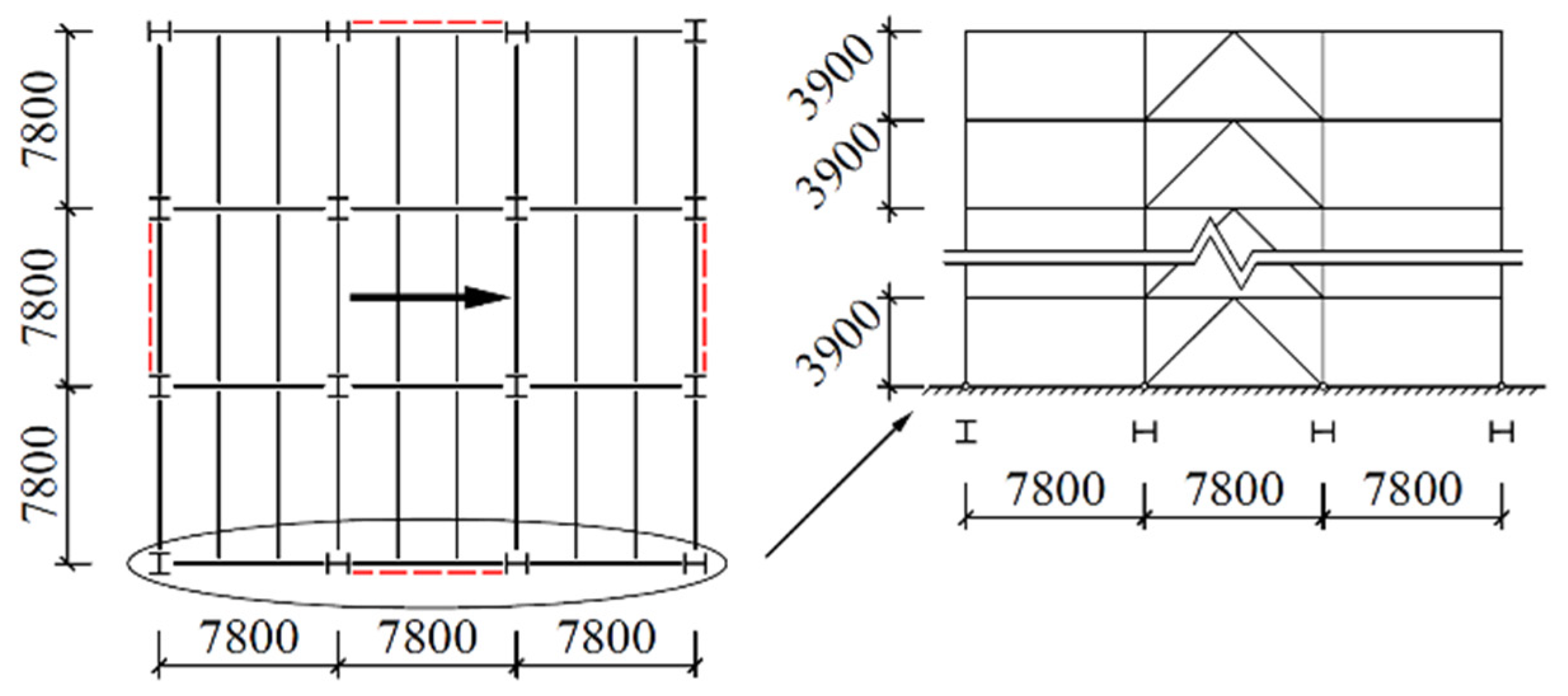
2.1. Prototype Design
2.2. Finite-Element Model
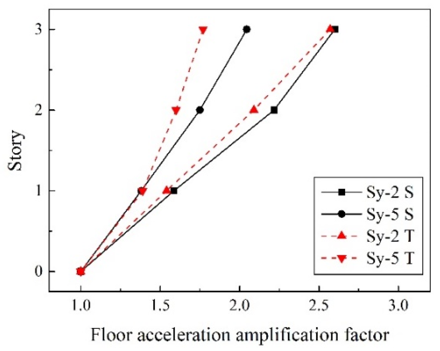
2.3. CBF Model Validation
3. Nonlinear Time-History-Analysis Strategy
4. Results Analysis
4.1. Comparison of Dynamic Characteristics
4.2. Comparison of Seismic Response in Failure Story
4.3. Comparison of Seismic Response of Residual Structures
5. Discussion
6. Conclusions
- (1)
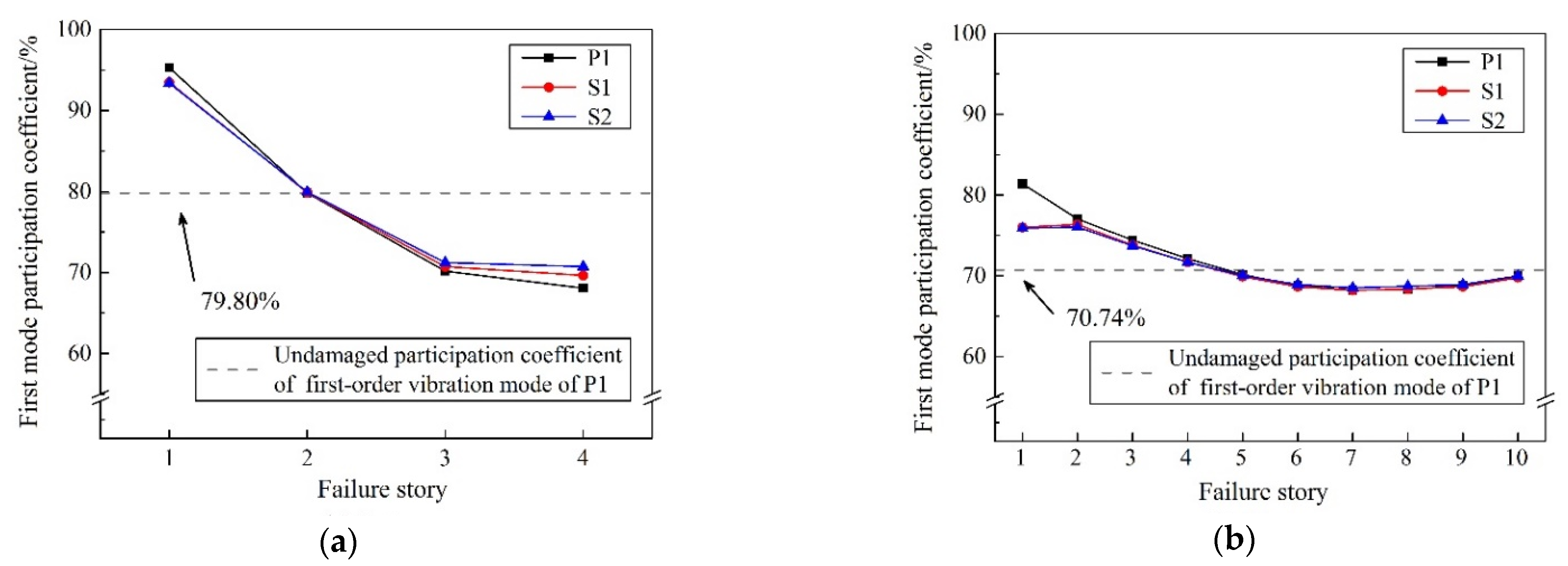
- Enhanced beam-to-column and column-to-base connections have little effect on the fundamental period (T1) of undamaged CBF structures, which is slightly reduced by 1.58–3.80% compared with the ideal pinned counterpart. However, the inherent reserve capacity is helpful for the remaining structure to maintain the original dynamic characteristics. The structural damage caused by brace failure will increase the T1 of residual structures, especially when the first-story brace fails. Reserve capacity could maintain this increment of T1 within 31.74% and 8.83% for 4-story and 10-story residual structures, respectively, after brace failure. Moreover, the failure of the first-story brace will greatly increase the participation coefficients of the first-order vibration mode (Γ1), which is 98.28% and 81.39% for 4-story and 10-story structures, respectively, and dominates the subsequent seismic response of the residual structures.
- (2)
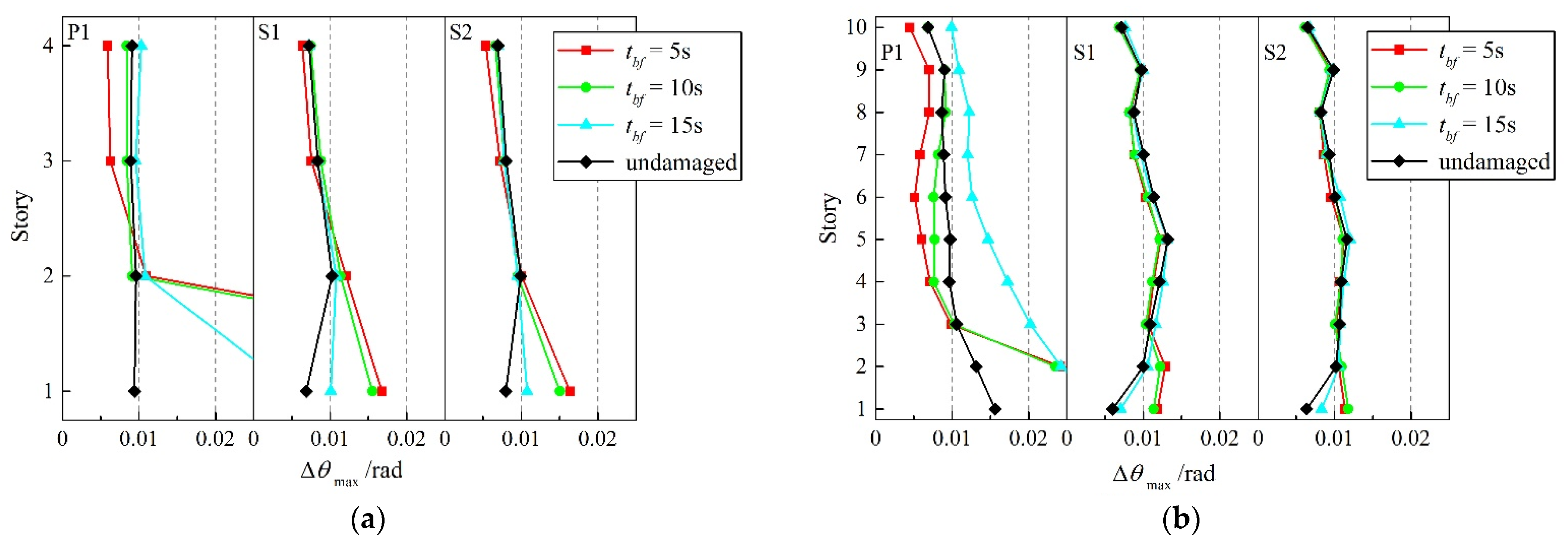
- Although the semi-rigid connection has little influence on the dynamic characteristics of the undamaged CBF structures, it can bring a significant seismic reserve capacity after the brace failure in the elasto-plastic stage, which can substantially reduce the increment of maximum story-drift angle (Δθmax) in residual structures. After the first-story brace fails at a very early time in the ideal pinner CBF structure, a soft-story mechanism is formed, and there is a high probability of overall collapse. While for the case of enhanced beam-to-column and column-to-base connections, the Δθmax of the failure story is maintained within 0.02 rad, and the corresponding increment compared with the undamaged ones is kept below 80.47% and 64.65% for 4-story and 10-story prototypes, respectively, which is conducive to avoid the overall collapse of the residual structures.
- (3)
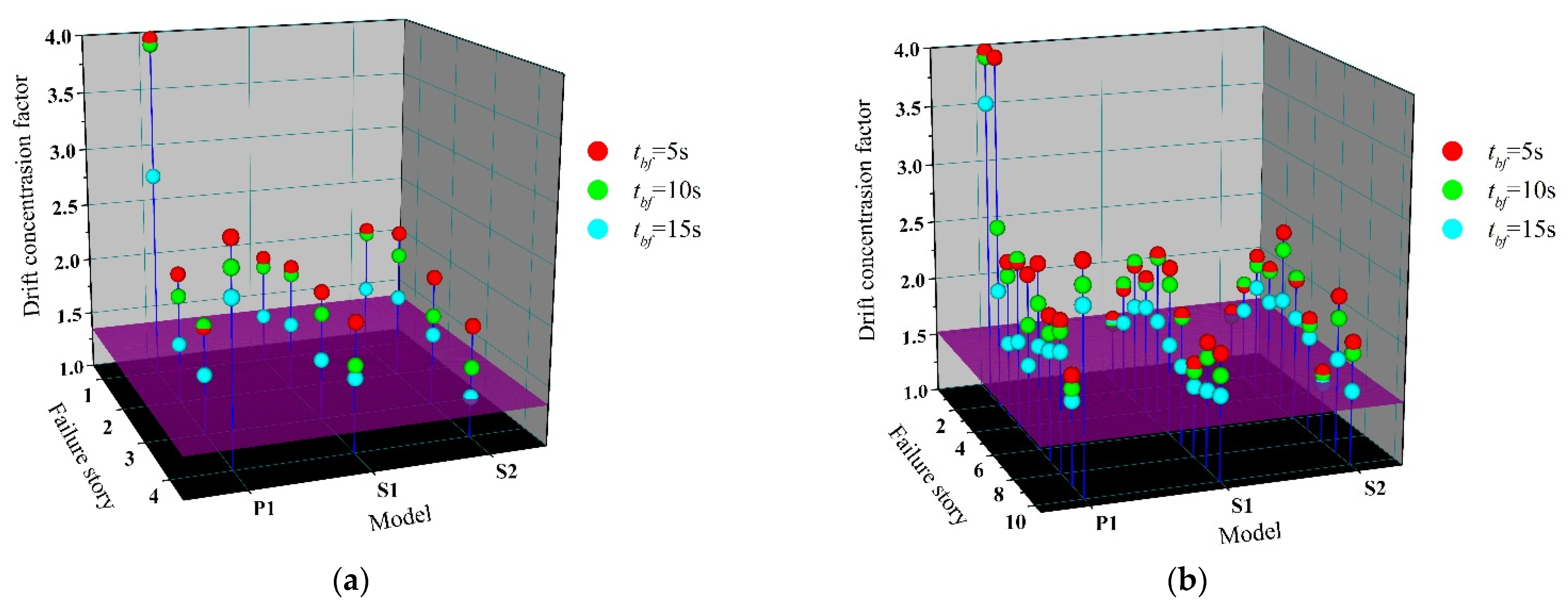
- The inherent reserve capacity originates from the semi-rigid connections and vertical continuous columns of the CBF structure that can also limit the increment of adjacent story drift caused by brace failure within 25%, prevent concentration of deformation, promote redistribution of the stiffness and displacement demand over the building height, and improve the overall seismic performance of the residual structure. For the case of semi-rigid connections, the drift-concentration factor (DCF) of the residual structure after brace failure is basically concentrated in the range of 1.5–2, which, from another point of view, proves that the overall deformation performance of the CBF structure, when considering the reserve capacity, is much better.
- (4)
- With the increase in the rotational stiffness of the beam-to-column and column-to-base connections as well as the delay of the brace-failure time, the influence of brace failure on the seismic response of the residual structures after brace failure is gradually weakened, and the risk of overall collapse of the residual structure is reduced. The exemption from the seismic-detailing requirement in an R = 3 CBF structure makes it impossible and unnecessary for designers to delay or even avoid the failure of the brace under a severe earthquake, by improving its low-cycle-fatigue life. However, the inherent reserve capacity could be a useful tool for preventing collapse of the CBF structures after the brace failure in moderate seismic regions.
Author Contributions
Funding
Institutional Review Board Statement
Informed Consent Statement
Data Availability Statement
Acknowledgments
Conflicts of Interest
References
- FEMA. Prestandard and Commentary for the Seismic Rehabilitation of Building; FEMA-356; Federal Emergency Management Agency: Washington, DC, USA, 2000.
- Broderick, B.M.; Elghazouli, A.Y.; Goggins, J. Earthquake testing and response analysis of concentrically-braced sub-frames. J. Constr. Steel Res. 2007, 64, 997–1007. [Google Scholar] [CrossRef] [Green Version]
- Mahmoudi, M.; Zaree, M. Evaluating response modification factors of concentrically braced steel frames. J. Constr. Steel Res. 2010, 66, 1196–1204. [Google Scholar] [CrossRef]
- Amadio, C.; Bomben, L.; Noè, S. Design of X-Concentric Braced Steel Frame Systems Using an Equivalent Stiffness in a Modal Elastic Analysis. Buildings 2022, 12, 359. [Google Scholar] [CrossRef]
- Osteraas, J.; Krawinkler, H. The Mexico earthquake of September 19, 1985—Behavior of steel buildings. Earthq. Spectra 1989, 5, 51–88. [Google Scholar] [CrossRef]
- Tremblay, R.; Filiatrault, A.; Timler, P.; Bruneau, M. Performance of steel structures during the 1994 Northridge earthquake. Can. J. Civ. Eng. 1995, 22, 338–360. [Google Scholar] [CrossRef]
- Tremblay, R.; Filiatrault, A.; Bruneau, M.; Nakashima, M.; Prion, H.G.L.; De Vall, R. Seismic design of steel buildings: Lessons from the 1995 Hyogo-ken Nanbu earthquake. Can. J. Civ. Eng. 1996, 23, 727–756. [Google Scholar] [CrossRef]
- Hines, E.M.; Appel, M.E.; Cheever, P.J. Collapse Performance of Low-Ductility Chevron Braced Steel Frames in Moderate Seismic Regions. Eng. J. 2009, 46, 149–180. [Google Scholar]
- Callister, J.T.; Pakelnicky, R.G. Seismic Evaluation of Existing Low Ductility Braced Frame Building in California. In Structures Congress; ASCE: Reston, VA, USA, 2011; pp. 2756–2767. [Google Scholar]
- Fahnestock, L.A.; Hines, E.M.; Tremblay, R.; Bradley, C.R.; Nelson, J.; Beland, T.; Davaran, A.; Sizemore, J. Reserve capacity and implications for seismic collapse prevention for low-ductility braced frames in moderate seismic regions. In Proceedings of the Tenth U.S. National Conference on Earthquake Engineering, Anchorage, AL, USA, 22 July 2014. [Google Scholar]
- Stoakes, C.D.; Fahnestock, L.A. Cyclic flexural analysis and behavior of beam-column connections with gusset plates. J. Constr. Steel Res. 2012, 72, 227–239. [Google Scholar] [CrossRef]
- Zhang, W.-Y.; Zhou, Y.; Zhang, Y.-C. Influence of gusset plate connections on the secondary moments in beams and columns of braced frames. J. Harbin Inst. Technol. 2013, 45, 1–7. [Google Scholar]
- Thornton, W.A.; Muir, L.S. Design of vertical bracing connections for high-seismic drift. Mod. Steel Constr. 2009. Available online: https://www.aisc.org/globalassets/modern-steel/archives/2009/03/2009v03_vertical_bracing.pdf (accessed on 19 May 2022).
- Stoakes, C.D.; Fahnestock, L.A. Cyclic flexural testing of concentrically braced frame beam-column connections. J. Struct. Eng. 2011, 137, 739–747. [Google Scholar] [CrossRef]
- Peloso, S.; Casarotti, C.; Dacarro, F.; Sinopoli, G. Response of an Existing Two-Storey RC Frame Designed for Gravity Loads: In Situ Pushover Tests and Numerical Analyses. Buildings 2020, 10, 227. [Google Scholar] [CrossRef]
- Liu, J.; Astaneh-Asl, A. Cyclic testing of simple connections including the effect of the slab. J. Struct. Eng. 2000, 126, 32–39. [Google Scholar] [CrossRef]
- Liu, J.; Astaneh-Asl, A. Moment–rotation parameters for composite shear tab connections. J. Struct. Eng. 2004, 130, 1371–1380. [Google Scholar] [CrossRef]
- Abolmaali, A.; Kukreti, A.; Motahari, A.; Ghassemieh, M. Energy dissipation characteristics of semi-rigid connections. J. Constr. Steel Res. 2009, 65, 1187–1197. [Google Scholar] [CrossRef]
- Abolmaali, A.; Kukreti, A.R.; Razavi, H. Hysteresis behavior of semi-rigid double web angle steel connections. J. Constr. Steel Res. 2003, 59, 1057–1082. [Google Scholar] [CrossRef]
- Lin, T.; Wang, Z.; Hu, F.; Wang, P. Finite-Element Analysis of High-Strength Steel Extended End-Plate Connections under Cyclic Loading. Materials 2022, 15, 2912. [Google Scholar] [CrossRef]
- Picard, A.; Beaulieu, D. Behavior of a simple column base connection. Can. J. Civ. Eng. 1985, 12, 126–136. [Google Scholar] [CrossRef]
- Picard, A.; Beaulieu, D.; Perusse, B. Rotational restraint of a simple column base connection. Can. J. Civ. Eng. 1987, 14, 49–57. [Google Scholar] [CrossRef]
- Bradley, R.C.; Sizemore, J.; Nelson, J.; Tremblay, R.; Hines, E.M.; Fahnestock, L. Large-scale testing of low-ductility concentrically-braced frames. In Structures Congress; ASCE: Reston, VA, USA, 2014; pp. 2417–2428. [Google Scholar]
- Tartaglia, R.; Milone, A.; Prota, A.; Landolfo, R. Seismic Retrofitting of Existing Industrial Steel Buildings: A Case-Study. Materials 2022, 15, 3276. [Google Scholar] [CrossRef]
- Kim, Y.; Shahriyer, H.; Hu, J. Seismic Performance Evaluation According to HSS and CFST Columns of 3D Frame Buildings with Rubber Friction Bearing (RFB). Materials 2022, 15, 1281. [Google Scholar] [CrossRef] [PubMed]
- GB 50011-2010; Code for Seismic Design of Buildings. Architecture & Building Press: Beijing, China, 2010; Volume 31–35, pp. 43–47.
- GB 50017-2017; Standard for Design of Steel Structures. Architecture & Building Press: Beijing, China, 2017; pp. 37–78.
- ANSI/AISC 341-16; Seismic Provisions for Structural Steel Buildings. AISC: Chicago, IL, USA, 2016; pp. 24–31.
- Hibbit, K.S. ABAQUS Analysis User’s Manual, Version 6.13; ABAQUS Inc.: Palo Alto, CA, USA, 2013. [Google Scholar]
- Cheng, H.; Zhang, R.; Zhang, T.; Wang, H.; Qu, C.; Zhang, P. P-Delta Effects on Nonlinear Seismic Behavior of Steel Moment-Resisting Frame Structures Subjected to Near-Fault and Far-Fault Ground Motions. Buildings 2022, 12, 205. [Google Scholar] [CrossRef]
- Zhang, W.-Y.; Mai, H.; Yu, H.-F. Shaking table test of special concentrically braced steel frame with pinned connections. J. Harbin Inst. Technol. 2016, 48, 17–24. [Google Scholar]
- Zhou, J.-W. The Seismic Performance Analysis for the Moment Frame-zipper Frame Dual System; Hebei University of Science and Technology: Shijiazhuang, China, 2016; pp. 33–37. [Google Scholar]
- Berman, J.W.; UW Civil & Environmental Engineering, UW College of Engineering, Seattle, WA, USA. Personal Communication, 2013.
- Cui, Y.; Wang, F.-Z.; Yu, G.-S. Effect of column base stiffness on seismic behavior of steel frame under severe earthquake. Earthq. Eng. Eng. Dyn. 2016, 36, 162–169. [Google Scholar]
- Gregory, A.; Yoshihiro, K.; Charles, R. Effect of column stiffness on braced frame seismic behavior. J. Struct. Eng. 2004, 130, 381–391. [Google Scholar]
- Christopoulos, C.; Trembly, R.; Kim, J.; Lacerte, M. Self-centering energy dissipative bracing system for the seismic resistance of structures: Development and validation. J. Struct. Eng. 2008, 134, 96–107. [Google Scholar] [CrossRef]
- ASCE/SEI 7-16; Minimum Design Loads and Associated Criteria for Buildings and Other Structures. American Society of Civil Engineers: Reston, VA, USA, 2017; pp. 89–92.


| Story | Braced Frame | Gravity Frame | |||
|---|---|---|---|---|---|
| Column | Girder | Brace | Column | Beam | |
| 4 | H400 × 400 × 15 × 15 | H950 × 360 × 18 × 22 | H245 × 210 × 7 × 9 | H400 × 400 × 15 × 15 | H600 × 240 × 14 × 18 |
| 3 | H400 × 400 × 15 × 15 | H1000 × 400 × 20 × 24 | H260 × 230 × 8 × 10 | H400 × 400 × 15 × 15 | H600 × 240 × 14 × 18 |
| 2 | H400 × 400 × 15 × 15 | H1000 × 400 × 20 × 24 | H275 × 255 × 8.5 × 10 | H400 × 400 × 15 × 15 | H600 × 240 × 14 × 18 |
| 1 | H400 × 400 × 15 × 15 | H1050 × 400 × 20 × 24 | H280 × 270 × 9 × 11 | H400 × 400 × 15 × 15 | H600 × 240 × 14 × 18 |
| Story | Braced Frame | Gravity Frame | |||
|---|---|---|---|---|---|
| Column | Girder | Brace | Column | Beam | |
| 10 | H400 × 400 × 15 × 15 | H950 × 360 × 18 × 22 | H245 × 210 × 7 × 9 | H400 × 400 × 15 × 15 | H600 × 240 × 14 × 18 |
| 9 | H400 × 400 × 15 × 15 | H950 × 360 × 18 × 22 | H260 × 220 × 7 × 9 | H400 × 400 × 15 × 15 | H600 × 240 × 14 × 18 |
| 8 | H550 × 500 × 20 × 22 | H1000 × 400 × 20 × 24 | H260 × 230 × 8 × 10 | H400 × 400 × 15 × 15 | H600 × 240 × 14 × 18 |
| 7 | H550 × 500 × 20 × 22 | H1000 × 400 × 20 × 24 | H260 × 230 × 8 × 10 | H400 × 400 × 15 × 15 | H600 × 240 × 14 × 18 |
| 6 | H550 × 500 × 20 × 22 | H1000 × 400 × 20 × 24 | H270 × 245 × 8 × 10 | H400 × 400 × 15 × 15 | H600 × 240 × 14 × 18 |
| 5 | H550 × 500 × 20 × 22 | H1000 × 400 × 20 × 24 | H270 × 245 × 8 × 10 | H400 × 400 × 15 × 15 | H600 × 240 × 14 × 18 |
| 4 | H600 × 550 × 22 × 24 | H1000 × 400 × 20 × 24 | H275 × 255 × 8.5 × 10 | H400 × 400 × 15 × 15 | H600 × 240 × 14 × 18 |
| 3 | H600 × 550 × 22 × 24 | H1050 × 400 × 20 × 24 | H280 × 270 × 9 × 11 | H400 × 400 × 15 × 15 | H600 × 240 × 14 × 18 |
| 2 | H700 × 650 × 24 × 26 | H1050 × 400 × 20 × 24 | H280 × 270 × 9 × 11 | H400 × 400 × 15 × 15 | H600 × 240 × 14 × 18 |
| 1 | H700 × 650 × 24 × 26 | H1050 × 400 × 20 × 24 | H280 × 270 × 9 × 11 | H400 × 400 × 15 × 15 | H600 × 240 × 14 × 18 |
| Model | P1 | S1 | S2 | |
|---|---|---|---|---|
| Connection | ||||
| Gravity frame | beam-to-column | pin | a | a |
| column-to-base | pin | rigid | rigid | |
| Braced frame | brace-to-frame | pin | pin | pin |
| beam-to-column | pin | b | c | |
| column-to-base | pin | rigid | rigid |
| Physical Property | Parameter | Scaling Factor |
|---|---|---|
| Geometry | Length | 1/4 |
| Material | Stress | 1/1 |
| Elastic modulus | 1/1 | |
| Poisson’s ratio | 1/1 | |
| Mass | 1/43.04 | |
| Load | Story shear | 1/16 |
| Dynamic | Time | 1/3.28 |
| Velocity | 1/1.22 | |
| Acceleration | 2.69/1 |
| Story | Brace | Width-to-Thickness Ratio (Slenderness Ratio) | Corner Gusset Plate | Mid-Span Gusset Plate | |||||||||||
|---|---|---|---|---|---|---|---|---|---|---|---|---|---|---|---|
| a | b | c | e | t | Sketch | a | b | c | d | e | t | Sketch | |||
| 3 | H62 × 62 × 3.75 × 3.75 | 5.8 (111) | 114.5 | 56.6 | 82 | 0 (0t) | 8 | 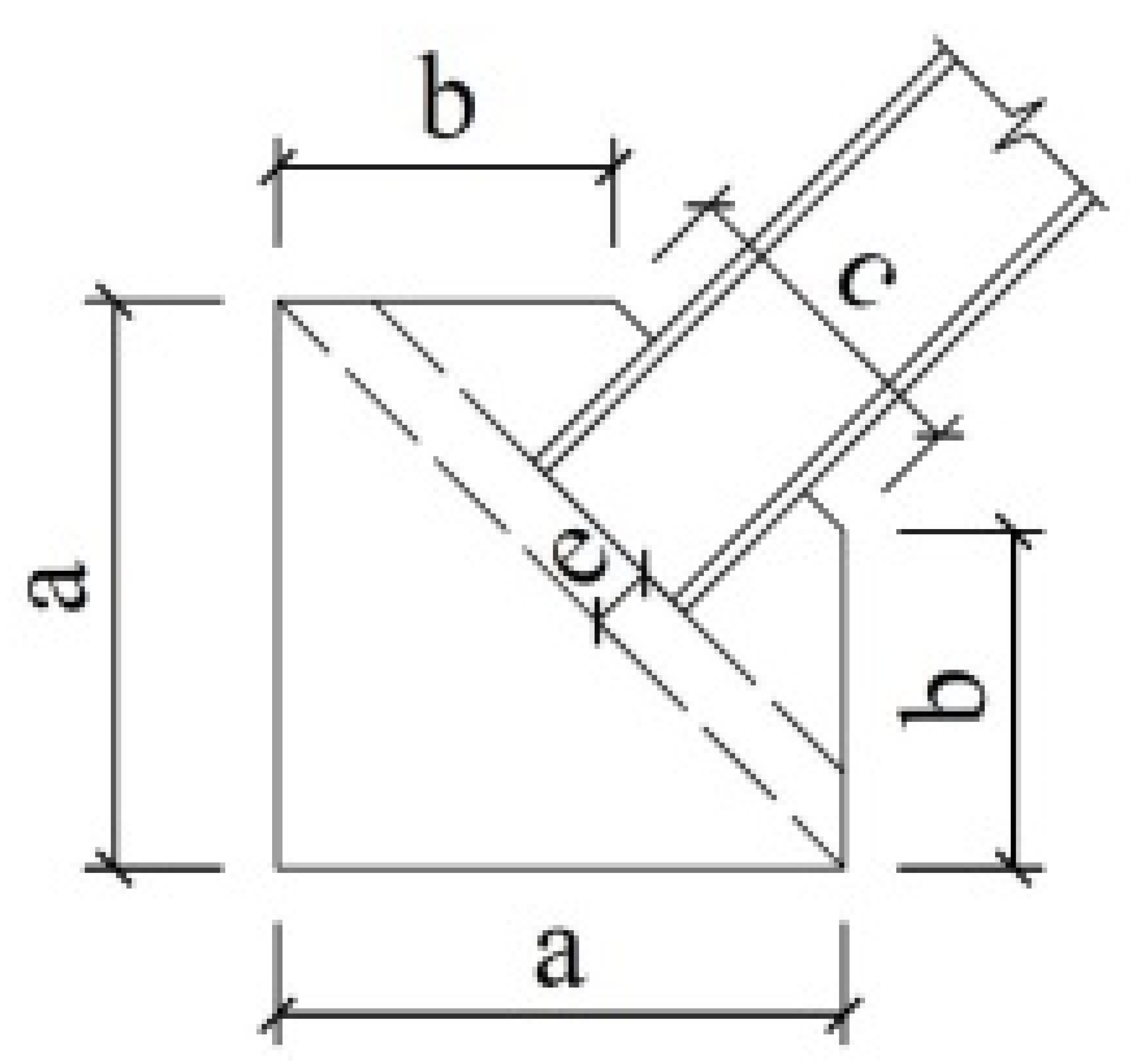 | 268.3 | 37.2 | 82 | 152.4 | 16 (2t) | 8 | 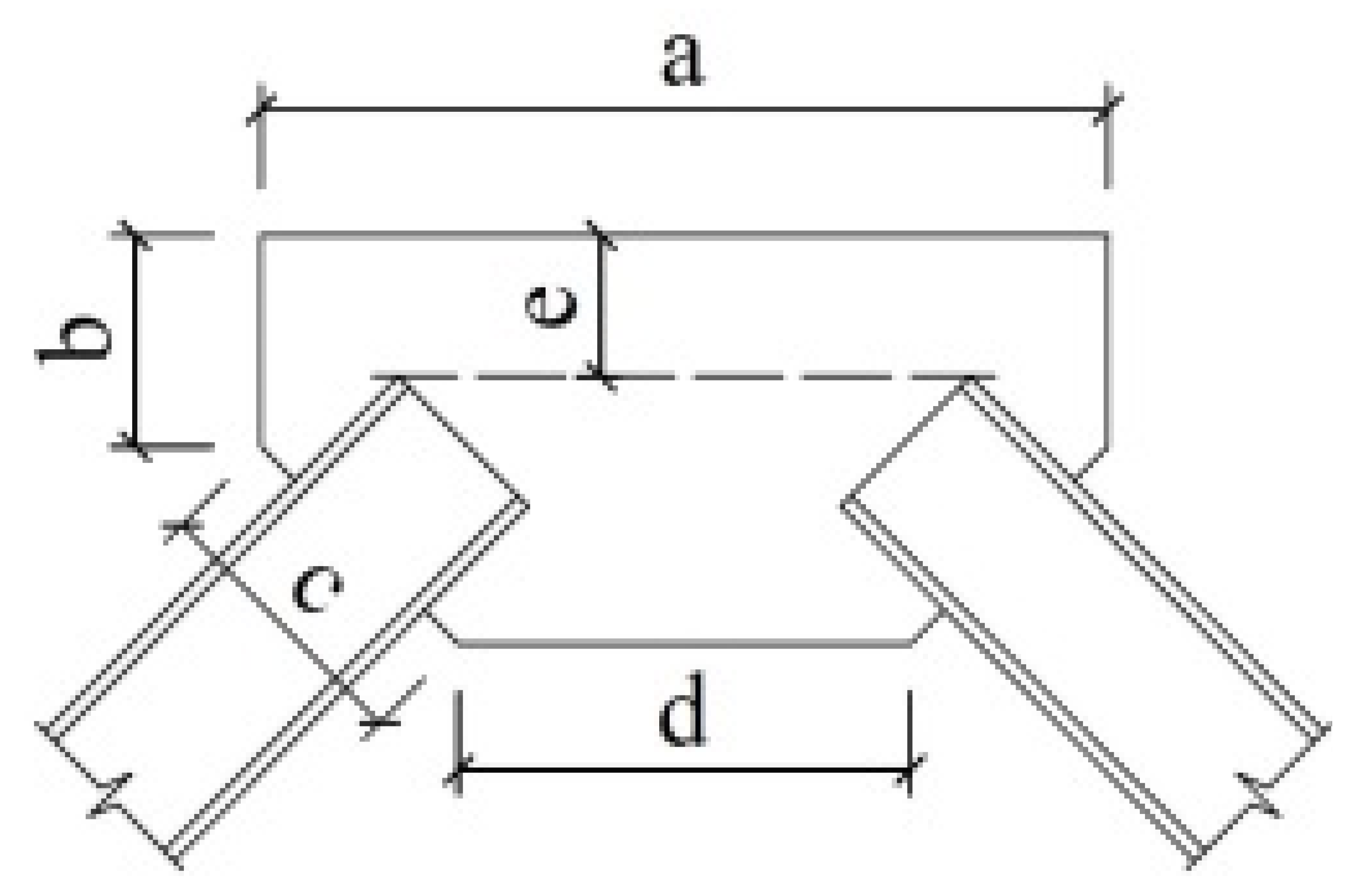 |
| 2 | H35 × 35 × 3 × 3 | 5.3 (120) | 101.0 | 60.0 | 58 | 12 (2t) | 6 | 308.0 | 74.0 | 55 | 226.0 | 60 (10t) | 6 | ||
| 1 | H38 × 38 × 3 × 3 | 7.8 (70.6) | 101.0 | 60.0 | 58 | 12 (2t) | 6 | 308.0 | 74.0 | 58 | 226.0 | 60 (10t) | 6 | ||
| Thickness/mm | E/105 MPa | Fy/MPa | Fu/MPa | Elongation/% |
|---|---|---|---|---|
| 3.00 | 1.90 | 296 | 397 | 34.6 |
| 3.75 | 1.95 | 294 | 445 | 36.8 |
| 6.00 | 2.05 | 292 | 426 | 30.9 |
| 8.00 | 2.14 | 288 | 448 | 32.5 |
| Condition | Ground Motion | Earthquake Intensity | PGA/gal | |
|---|---|---|---|---|
| Set Value | Measured Value | |||
| W-1 | White noise | - | Very small | |
| Sy-1 | Sy | 8-degree frequent intensity | 188.3 | 87.9 |
| Sy-2 | Sy | 188.3 | 225.8 | |
| W-2 | White noise | - | Very small | |
| Sy-3 | Sy | 8-degree basic intensity | 538.0 | 295.4 |
| Sy-4 | Sy | 538.0 | 671.4 | |
| W-3 | White noise | - | Very small | |
| Sy-5 | Sy | 9-degree rare intensity | 1668.0 | 1914.8 |
| Sy-6 | Sy | 1668.0 | 1952.6 | |
| W-4 | White noise | - | Very small | |
| Sy-7 | Sy | 3 continuous motions | 2218.4 | 2252.9 |
| Sy-8 | Sy | 3 continuous motions | 2218.4 | 2494.0 |
| Sy-9 | Sy | 3 continuous motions | 2351.9 | 2748.6 |
| Sy-10 | Sy | 5 continuous motions | 2351.9 | 2516.0 |
| W-5 | White noise | - | Very small | |
| Model | P1 | S1 | S2 | |
|---|---|---|---|---|
| Period | ||||
| 4-story | 1st | 0.570 | 0.561 | 0.557 |
| 2nd | 0.202 | 0.197 | 0.194 | |
| 3rd | 0.125 | 0.122 | 0.121 | |
| 10-story | 1st | 1.630 | 1.592 | 1.568 |
| 2nd | 0.512 | 0.496 | 0.489 | |
| 3rd | 0.272 | 0.264 | 0.261 |
Publisher’s Note: MDPI stays neutral with regard to jurisdictional claims in published maps and institutional affiliations. |
© 2022 by the authors. Licensee MDPI, Basel, Switzerland. This article is an open access article distributed under the terms and conditions of the Creative Commons Attribution (CC BY) license (https://creativecommons.org/licenses/by/4.0/).
Share and Cite
Zhao, Z.; Zhang, W.; Ding, Y.; Li, H. Effects of Reserve Capacity on Seismic Response of Concentrically Braced Frames by Considering Brace Failure. Materials 2022, 15, 4377. https://doi.org/10.3390/ma15134377
Zhao Z, Zhang W, Ding Y, Li H. Effects of Reserve Capacity on Seismic Response of Concentrically Braced Frames by Considering Brace Failure. Materials. 2022; 15(13):4377. https://doi.org/10.3390/ma15134377
Chicago/Turabian StyleZhao, Zengyang, Wenyuan Zhang, Yukun Ding, and Hongwei Li. 2022. "Effects of Reserve Capacity on Seismic Response of Concentrically Braced Frames by Considering Brace Failure" Materials 15, no. 13: 4377. https://doi.org/10.3390/ma15134377
APA StyleZhao, Z., Zhang, W., Ding, Y., & Li, H. (2022). Effects of Reserve Capacity on Seismic Response of Concentrically Braced Frames by Considering Brace Failure. Materials, 15(13), 4377. https://doi.org/10.3390/ma15134377