
Preparation and Band Gap Characteristics of Composite Film/Substrate Instability System


Abstract
:1. Introduction
2. Finite Element Simulation
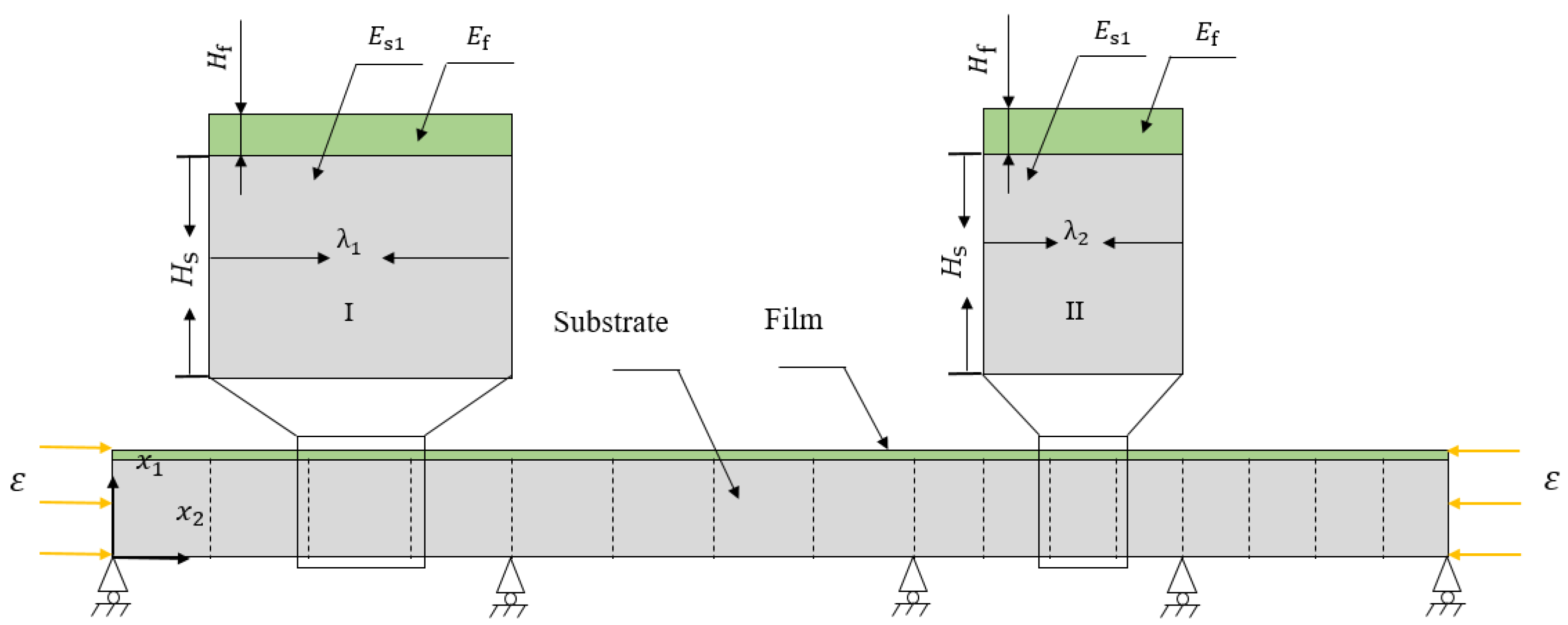
2.1. Model
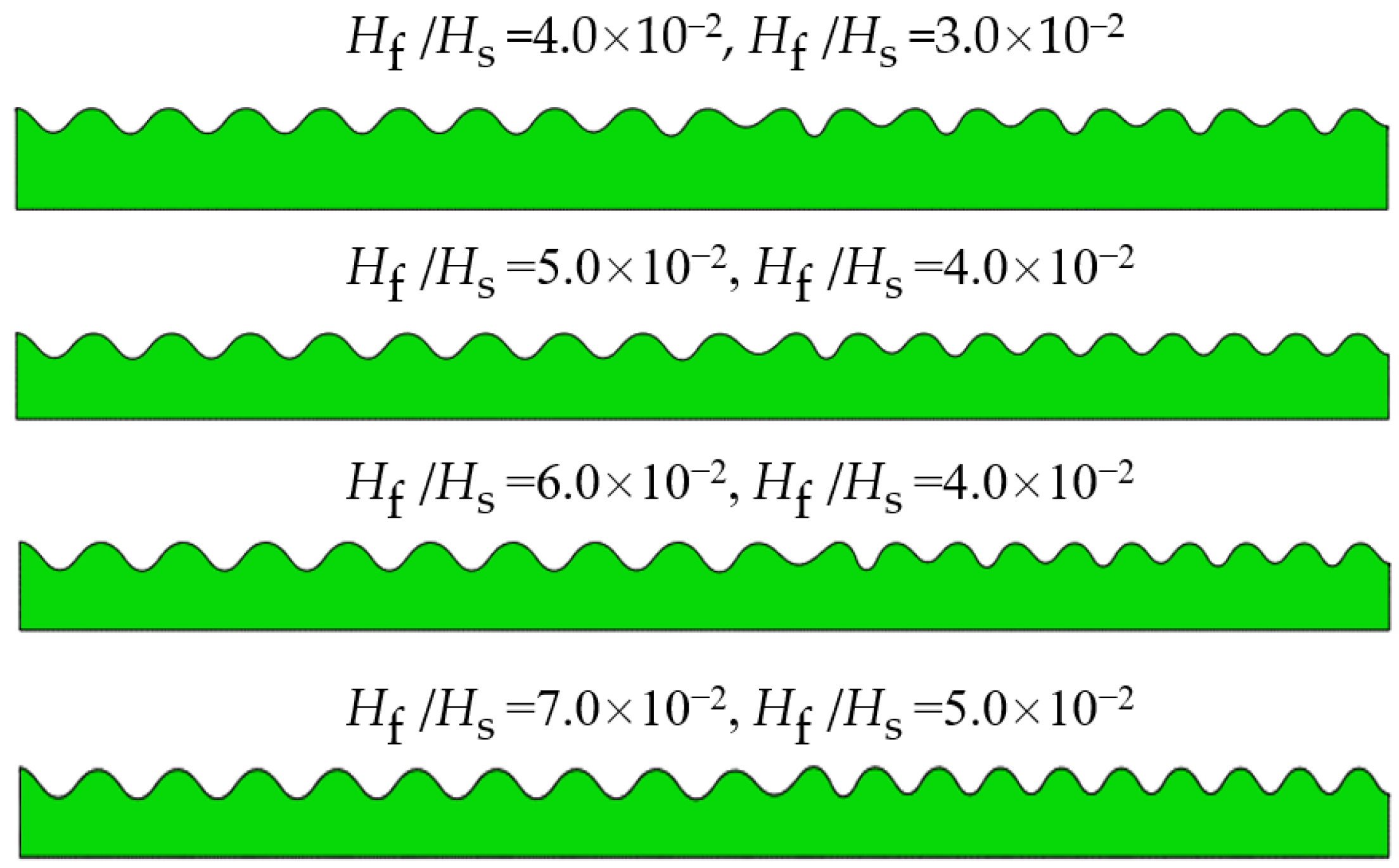
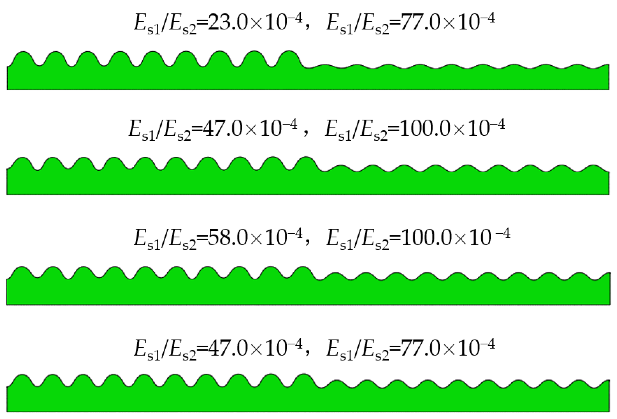
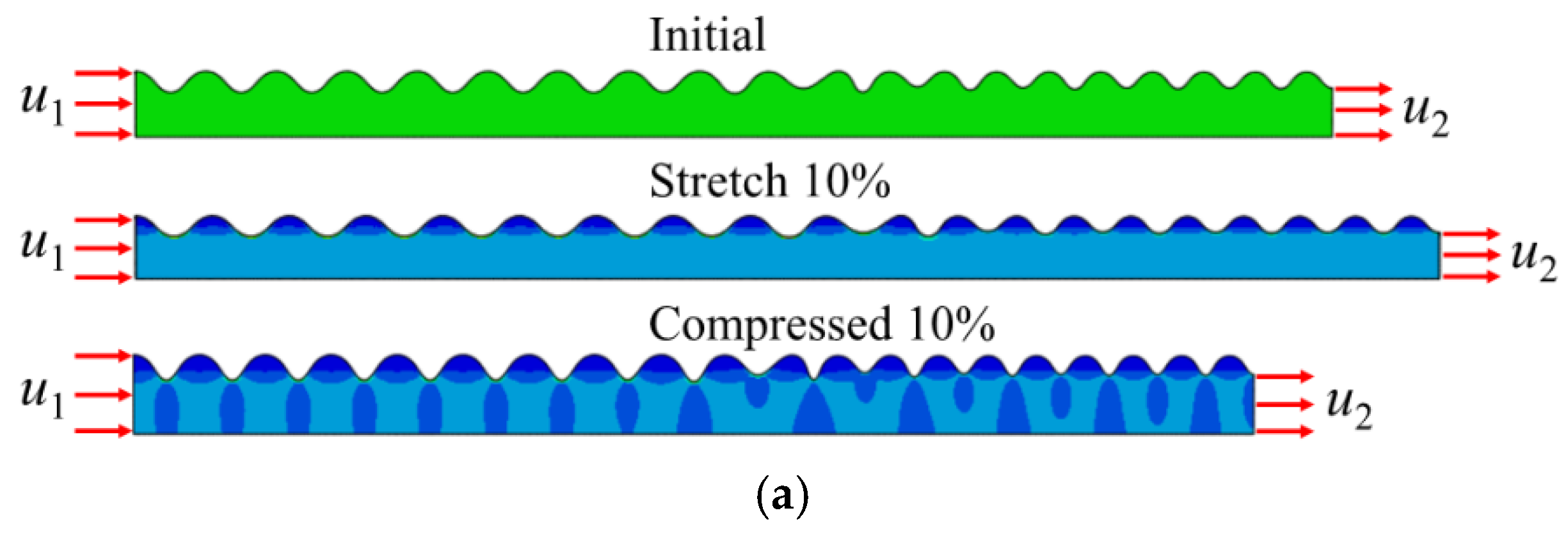
2.2. Wrinkling Patterns in the Composite Bilayer System
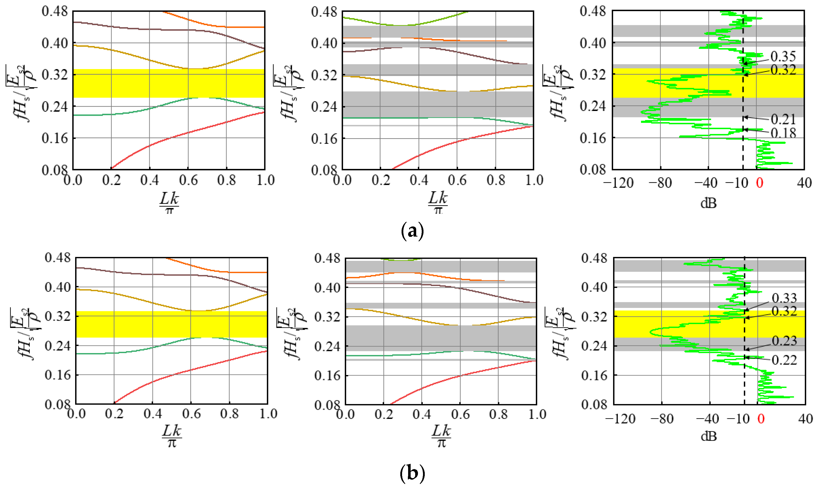
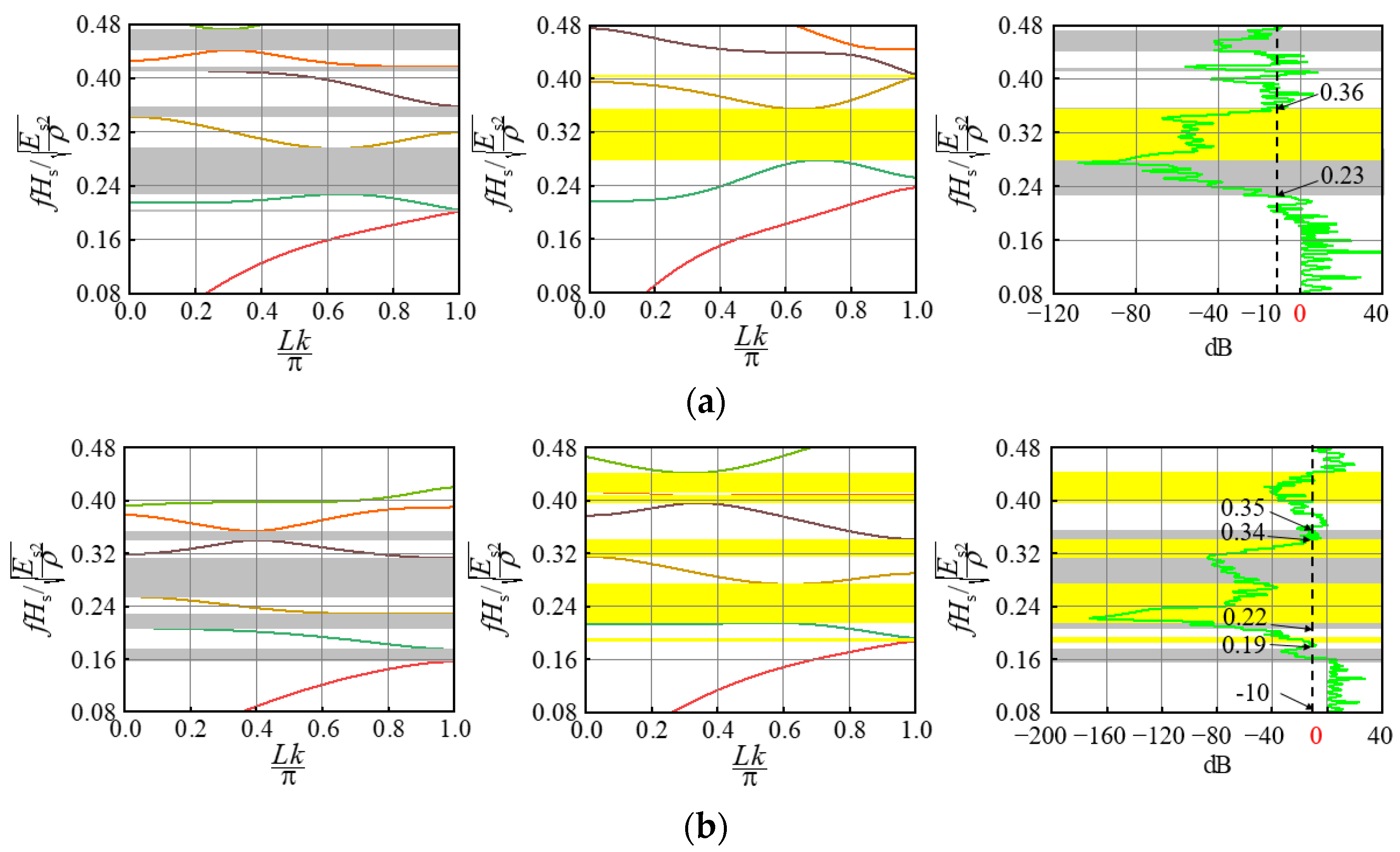
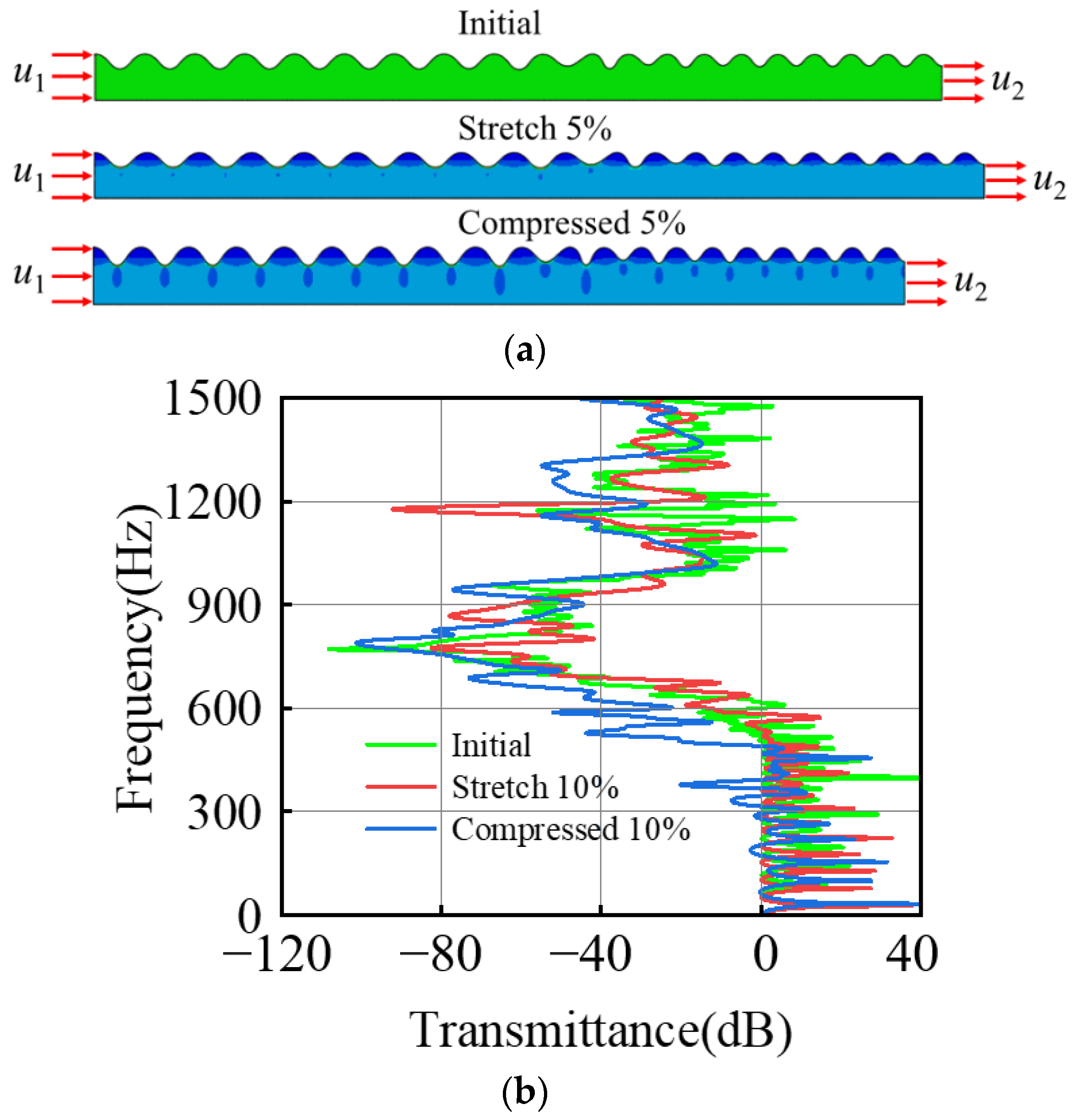
2.3. Bandgap Structure of the Composite Bilayer System
3. The Experiment
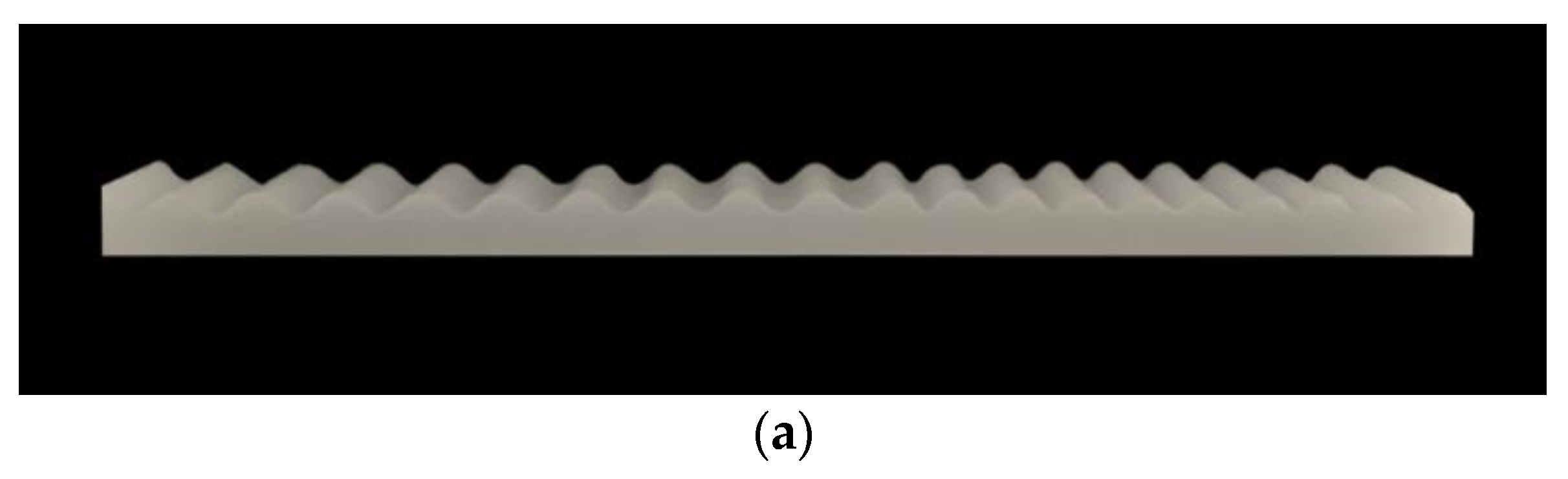
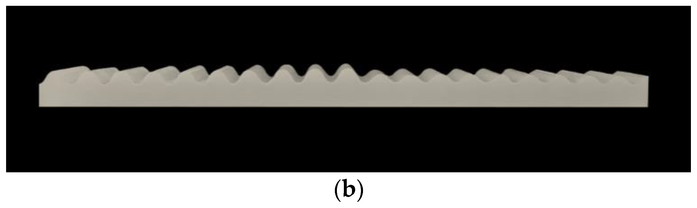
3.1. Wrinkled Sample
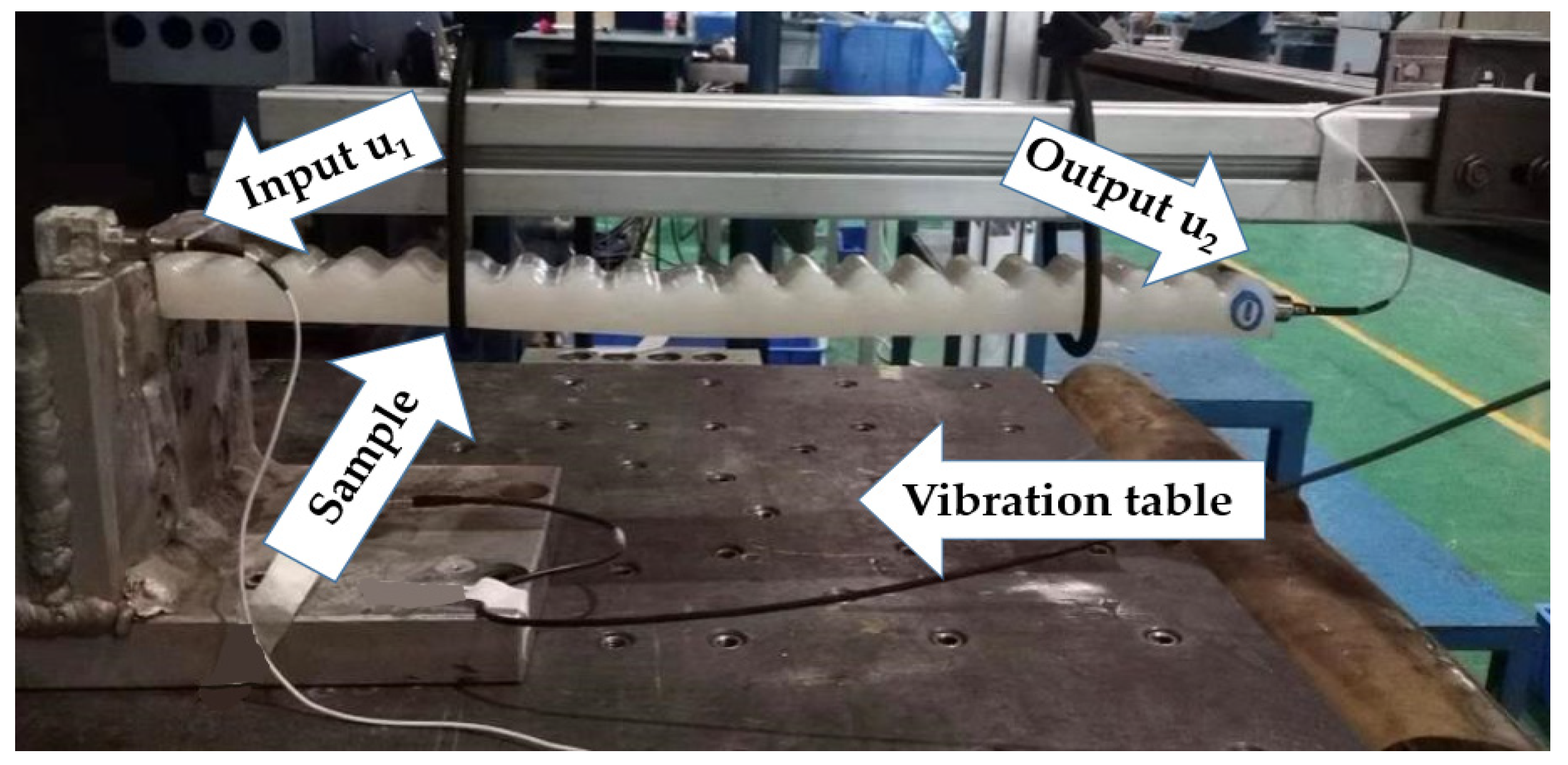
3.2. Vibration Test
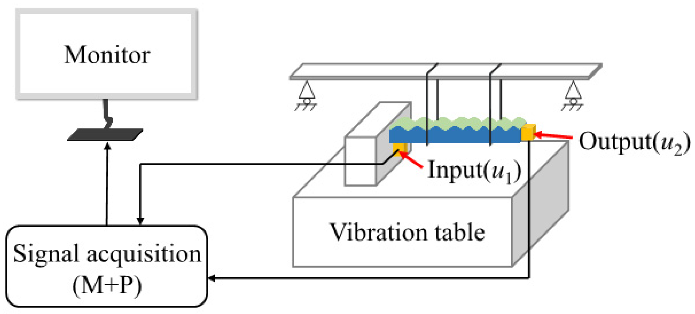
3.2.1. Device
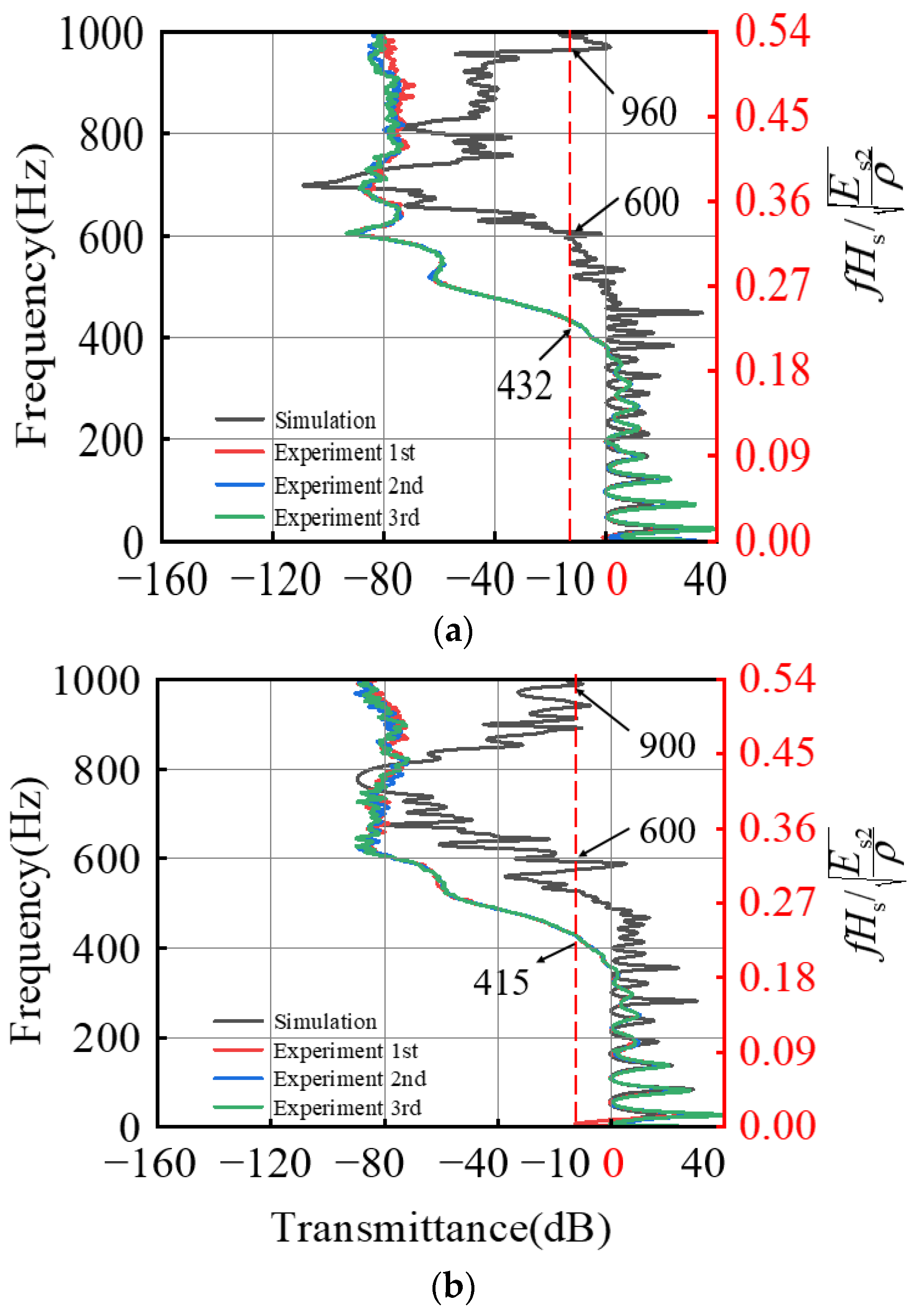
3.2.2. Test Results
4. Discussion
5. Conclusions
Author Contributions
Funding
Institutional Review Board Statement
Informed Consent Statement
Data Availability Statement
Acknowledgments
Conflicts of Interest
References
- Yin, J.; Chen, X.; Sheinman, I. Anisotropic buckling patterns in spheroidal film/substrate systems and their implications in some natural and biological systems. J. Mech. Phys. Solids 2009, 57, 1470–1484. [Google Scholar] [CrossRef]
- Chen, X.; Yin, J. Buckling patterns of thin films on curved compliant substrates with applications to morphogenesis and three-dimensional micro-fabrication. Soft Matter 2010, 6, 5667–5680. [Google Scholar] [CrossRef]
- Genzer, J.; Groenewold, J. Soft matter with hard skin: From skin wrinkles to templating and material characterization. Soft Matter 2006, 2, 310–323. [Google Scholar] [CrossRef] [PubMed]
- Li, B.; Cao, Y.P.; Feng, X.Q.; Gao, H. Mechanics of morphological instabilities and surface wrinkling in soft materials: A review. Soft Matter 2012, 8, 5728–5745. [Google Scholar] [CrossRef]
- Akl, W.; Baz, A. Multi-cell Active Acoustic Metamaterial with Programmable Bulk Modulus. J. Intell. Mater. Syst. Struct. 2010, 21, 541–556. [Google Scholar] [CrossRef]
- Chung, J.Y.; Nolte, A.; Stafford, C.M. Surface Wrinkling: A Versatile Platform for Measuring Thin-Film Properties. Adv. Mater. 2011, 23, 349–368. [Google Scholar] [CrossRef] [PubMed]
- Kim, D.H.; Rogers, J.A. Stretchable Electronics: Materials Strategies and Devices. Adv. Mater. 2008, 20, 4887–4892. [Google Scholar] [CrossRef]
- Crosby, A.J. Why should we care about buckling? Soft Matter 2010, 6, 5660. [Google Scholar] [CrossRef]
- Alam, Z.; Sharma, A.K. Functionally Graded Soft Dielectric Elastomer Phononic Crystals: Finite Deformation, electro-elastic longitudinal waves, and band gaps tunability via electro-mechanical loading. Int. J. Appl. Mech. 2022. [Google Scholar] [CrossRef]
- Mei, H.; Huang, R.; Chung, J.Y.; Stafford, C.M.; Yu, H.H. Buckling modes of elastic thin films on elastic substrates. Appl. Phys. Lett. 2007, 90, 151902. [Google Scholar] [CrossRef]
- Wang, J.; Dai, G.; Huang, J. Thermal metamaterial: Fundamental, application, and outlook. Iscience 2020, 23, 101637. [Google Scholar] [CrossRef] [PubMed]
- Zhang, Z.; Duan, W.H.; Wang, C.M. Tunable wrinkling pattern in annular graphene under circular shearing at inner edge. Nanoscale 2012, 4, 5077–5081. [Google Scholar] [CrossRef] [PubMed]
- Ma, L.; He, L.; Ni, Y. Tunable hierarchical wrinkling: From models to applications. J. Appl. Phys. 2020, 127, 111101. [Google Scholar] [CrossRef]
- Wang, W.; Sun, Y.; He, L.; Ni, Y. Tunable spatially dependent wrinkling morphologies on pre-curved surfaces. Extrem. Mech. Lett. 2022, 50, 101551. [Google Scholar] [CrossRef]
- Li, M.; Hakimi, N.; Perez, R.; Waldman, S.; Kozinski, J.A.; Hwang, D.K. Microarchitecture for a Three-Dimensional Wrinkled Surface Platform. Adv. Mater. 2015, 27, 1880–1886. [Google Scholar] [CrossRef]
- Zheludev, N.I. The road ahead for metamaterials. Science 2010, 328, 582–583. [Google Scholar] [CrossRef]
- Ebata, Y.; Croll, A.B.; Crosby, A.J. Wrinkling and strain localizations in polymer thin films. Soft Matter 2012, 8, 9086–9091. [Google Scholar] [CrossRef]
- Torres, M.D.E.F.; De Espinosa, F.M.; Garcia-Pablos, D.; Garcia, N. Sonic Band Gaps in Finite Elastic Media: Surface States and Localization Phenomena in Linear and Point Defects. Phys. Rev. Lett. 1999, 82, 3054. [Google Scholar] [CrossRef]
- Casadei, F.; Dozio, L.; Ruzzene, M.; Cunefare, K.A. Periodic shunted arrays for the control of noise radiation in an enclosure. J. Sound Vib. 2010, 329, 3632–3646. [Google Scholar] [CrossRef]
- Ma, T.; Segawa, Y.; Miyazaki, Y.; Marumo, Y.; Imamura, Y.; Nonaka, T.; Sakata, Y. Effects of periodic waveform wrinkles on ultrasonic reflection characteristics in press forming. Procedia Manuf. 2018, 15, 969–975. [Google Scholar] [CrossRef]
- Rudykh, S.; Boyce, M.C. Transforming wave propagation in layered media via instability-induced interfacial wrinkling. Phys. Rev. Lett. 2014, 112, 034301. [Google Scholar] [CrossRef] [PubMed]
- Bayat, A.; Gordaninejad, F. Switching band-gaps of a phononic crystal slab by surface instability. Smart Mater. Struct. 2015, 24, 075009. [Google Scholar] [CrossRef]
- Wang, Y.F.; Wang, Y.Z.; Wu, B.; Chen, W.; Wang, Y.S. Tunable and active phononic crystals and metamaterials. Appl. Mech. Rev. 2020, 72, 040801. [Google Scholar] [CrossRef]
- Li, G.Y.; Zheng, Y.; Cao, Y.; Feng, X.Q.; Zhang, W. Controlling elastic wave propagation in a soft bilayer system via wrinkling-induced stress patterns. Soft Matter 2016, 12, 4204–4213. [Google Scholar] [CrossRef] [PubMed]
- Li, G.Y.; Zheng, Y.; Cao, Y. Tunable defect mode in a soft wrinkled bilayer system. Extrem. Mech. Lett. 2016, 9, 171–174. [Google Scholar] [CrossRef]
- Sharma, A.K.; Kosta, M.; Shmuel, G.; Amir, O. Gradient-based topology optimization of soft dielectrics as tunable phononic crystals. Compos. Struct. 2022, 280, 114846. [Google Scholar] [CrossRef]
- Sharma, A.K.; Joglekar, M.M.; Joglekar, D.M.; Alam, Z. Topology optimization of soft compressible phononic laminates for widening the mechanically tunable band gaps. Compos. Struct. 2022, 289, 115389. [Google Scholar] [CrossRef]
- Deng, J.M.; Zhang, M.G.; Li, Z.; Zhao, Z.G.; Ren, Y.; Lv, H.; Liu, H.D.; Jia, F.; Gu, B. Preparation and parametric analysis of film/substrate band-gap systems based on elastic instability. Eur. Phys. J. Plus 2022, 137, 686. [Google Scholar] [CrossRef]
- Huang, Z.Y.; Hong, W.; Suo, Z. Nonlinear analyses of wrinkles in a film bonded to a compliant substrate. J. Mech. Phys. Solids 2005, 53, 2101–2118. [Google Scholar] [CrossRef]
- Budiansky, B. Theory of buckling and post-buckling behavior of elastic structures. Adv. Appl. Mech. 1974, 14, 1–65. [Google Scholar]


| Thickness Ratio | Compressive Strain | Film Thickness (mm) | Substrate Thickness (mm) | Film Modulus (MPa) | Substrate Modulus (MPa) | Substrate Modulus (MPa) |
|---|---|---|---|---|---|---|
| 3.0 × 10⁻² | 20% | 0.6 | 18.0 | 6.9 | 13.8 × 10⁻³ | 3.0 |
| 4.0 × 10⁻² | 20% | 0.7 | 18.0 | 6.9 | 13.8 × 10⁻³ | 3.0 |
| 5.0 × 10⁻² | 20% | 0.9 | 18.0 | 6.9 | 13.8 × 10⁻³ | 3.0 |
| 6.0 × 10⁻² | 20% | 1.0 | 18.0 | 6.9 | 13.8 × 10⁻³ | 3.0 |
| 7.0 × 10⁻² | 20% | 1.2 | 18.0 | 6.9 | 13.8 × 10⁻³ | 3.0 |
| Modulus Ratio | Compressive Strain | Film Thickness (mm) | Substrate Thickness (mm) | Film Modulus (MPa) | Substrate Modulus (MPa) | Substrate Modulus (MPa) |
|---|---|---|---|---|---|---|
| 23.0 × 10⁻⁴ | 20% | 1.0 | 18.0 | 6.9 | 6.9 × 10⁻³ | 3.0 |
| 47.0 × 10⁻⁴ | 20% | 1.0 | 18.0 | 6.9 | 13.8 × 10⁻³ | 3.0 |
| 58.0 × 10⁻⁴ | 20% | 1.0 | 18.0 | 6.9 | 17.2 × 10⁻³ | 3.0 |
| 77.0 × 10⁻⁴ | 20% | 1.0 | 18.0 | 6.9 | 23.0 × 10⁻³ | 3.0 |
| 100.0 × 10⁻⁴ | 20% | 1.0 | 18.0 | 6.9 | 30.0 × 10⁻³ | 3.0 |
| Modulus Ratio | Compressive Strain | Film Thickness (mm) | Substrate Thickness (mm) | Film Modulus (MPa) | Basement Modulus (MPa) | Basement Modulus (MPa) |
|---|---|---|---|---|---|---|
| 1.0 | 20% | 1.0 | 18.0 | 3.0 | 13.8 × 10⁻³ | 3.0 |
| 2.3 | 20% | 1.0 | 18.0 | 6.9 | 13.8 × 10⁻³ | 3.0 |
| 4.0 | 20% | 1.0 | 18.0 | 11.8 | 13.8 × 10⁻³ | 3.0 |
| 8.0 | 20% | 1.0 | 18.0 | 23.7 | 13.8 × 10⁻³ | 3.0 |
| 12.0 | 20% | 1.0 | 18.0 | 35.5 | 13.8 × 10⁻³ | 3.0 |
Publisher’s Note: MDPI stays neutral with regard to jurisdictional claims in published maps and institutional affiliations. |
© 2022 by the authors. Licensee MDPI, Basel, Switzerland. This article is an open access article distributed under the terms and conditions of the Creative Commons Attribution (CC BY) license (https://creativecommons.org/licenses/by/4.0/).
Share and Cite
Lv, H.; Deng, J.; Ren, Y.; Zhang, H.; Zhang, W.; Zhang, M.; Liu, H.; Gu, B. Preparation and Band Gap Characteristics of Composite Film/Substrate Instability System. Materials 2022, 15, 6248. https://doi.org/10.3390/ma15186248
Lv H, Deng J, Ren Y, Zhang H, Zhang W, Zhang M, Liu H, Gu B. Preparation and Band Gap Characteristics of Composite Film/Substrate Instability System. Materials. 2022; 15(18):6248. https://doi.org/10.3390/ma15186248
Chicago/Turabian StyleLv, Huan, Jiaming Deng, Yi Ren, Hao Zhang, Wang Zhang, Mangong Zhang, Haidong Liu, and Bin Gu. 2022. "Preparation and Band Gap Characteristics of Composite Film/Substrate Instability System" Materials 15, no. 18: 6248. https://doi.org/10.3390/ma15186248
APA StyleLv, H., Deng, J., Ren, Y., Zhang, H., Zhang, W., Zhang, M., Liu, H., & Gu, B. (2022). Preparation and Band Gap Characteristics of Composite Film/Substrate Instability System. Materials, 15(18), 6248. https://doi.org/10.3390/ma15186248