

The Use of NDT Diagnostic Methods and Calculations in Assessing the Masonry Tower Crowned with the Steel Dome


Abstract
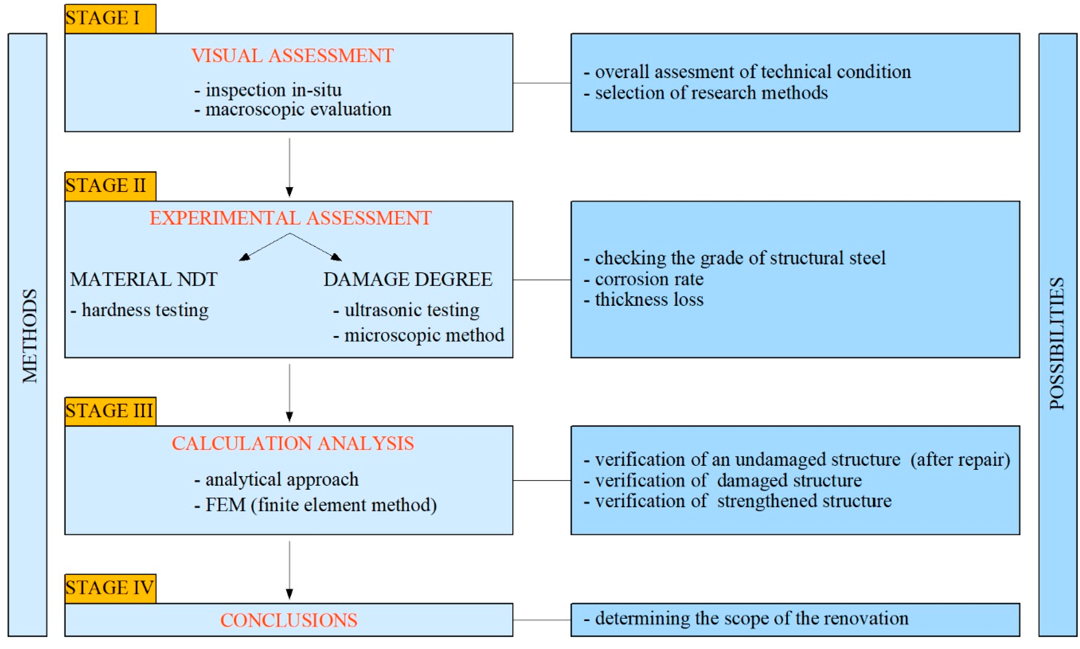
:1. Introduction
1.1. Visual Testing
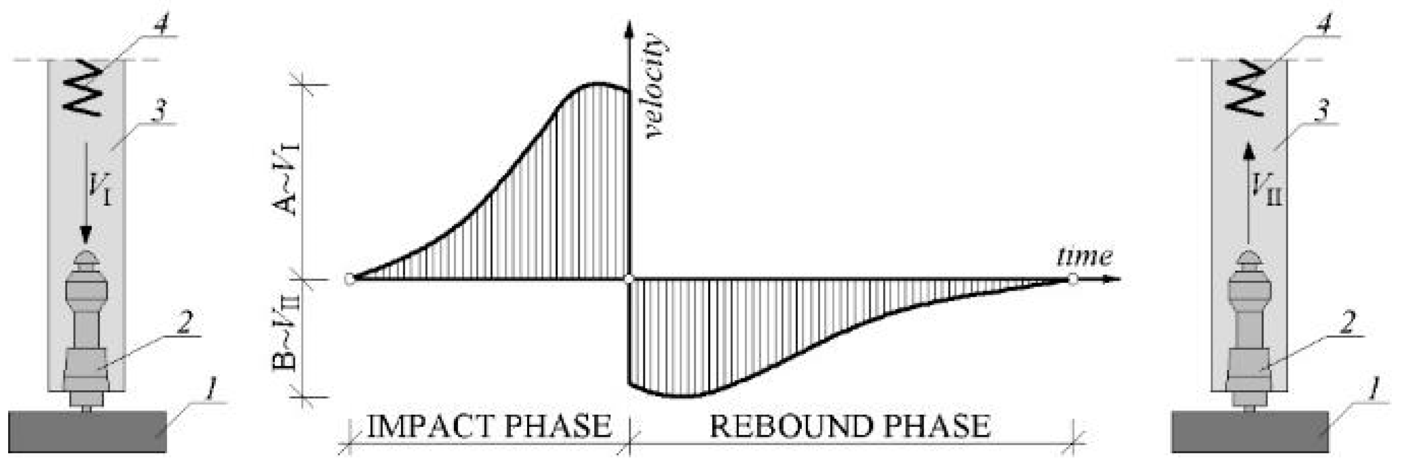
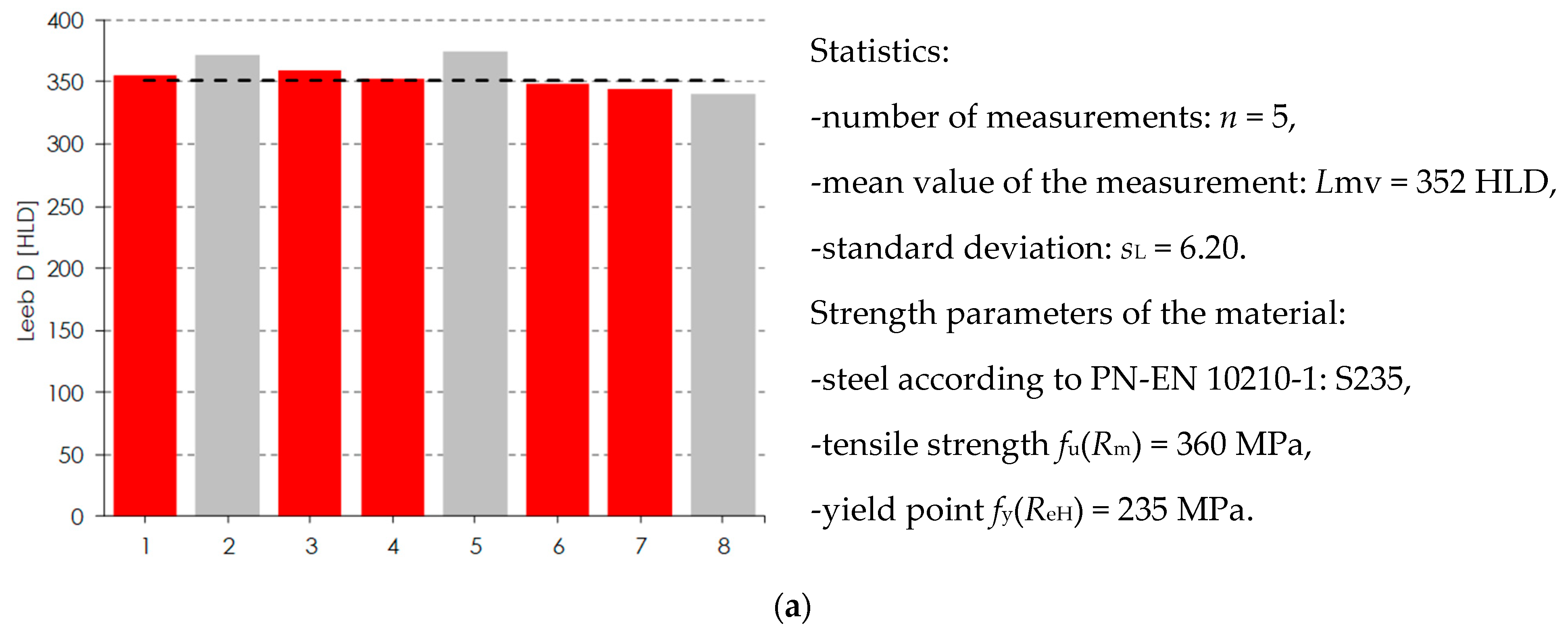
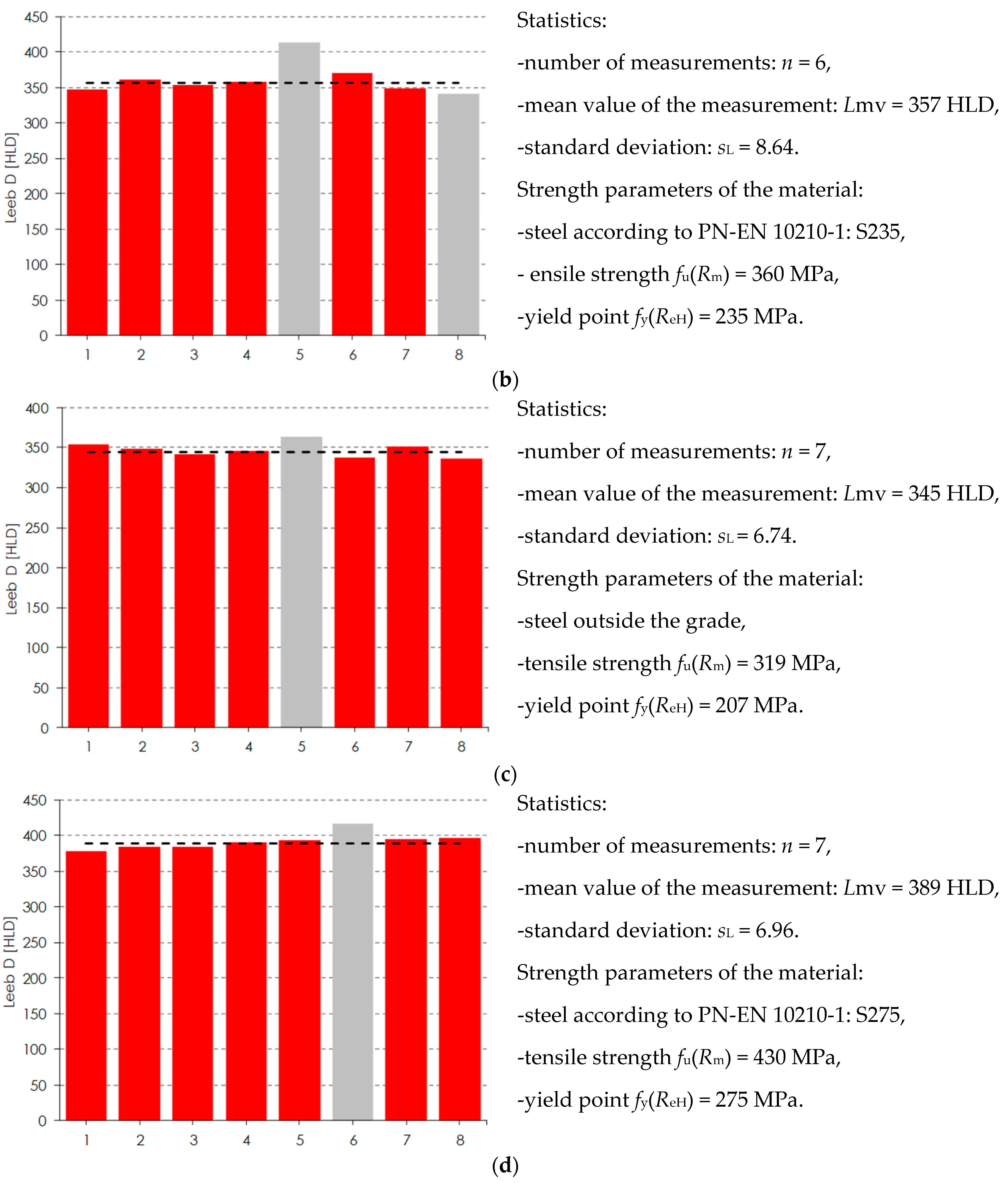
1.2. Hardness Testing
1.3. Ultrasonic Testing
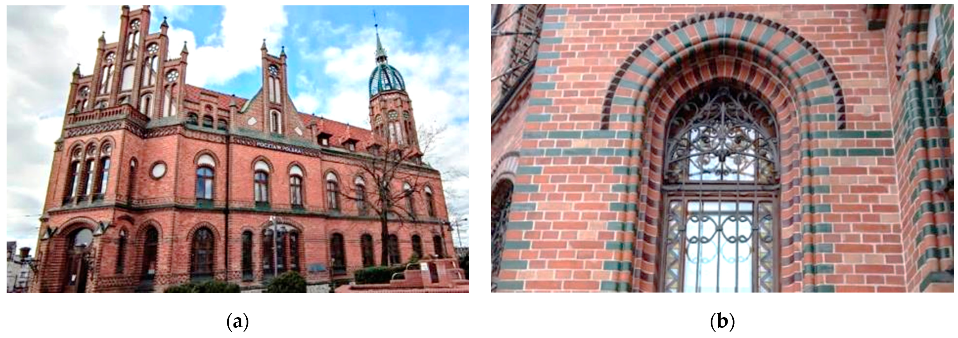
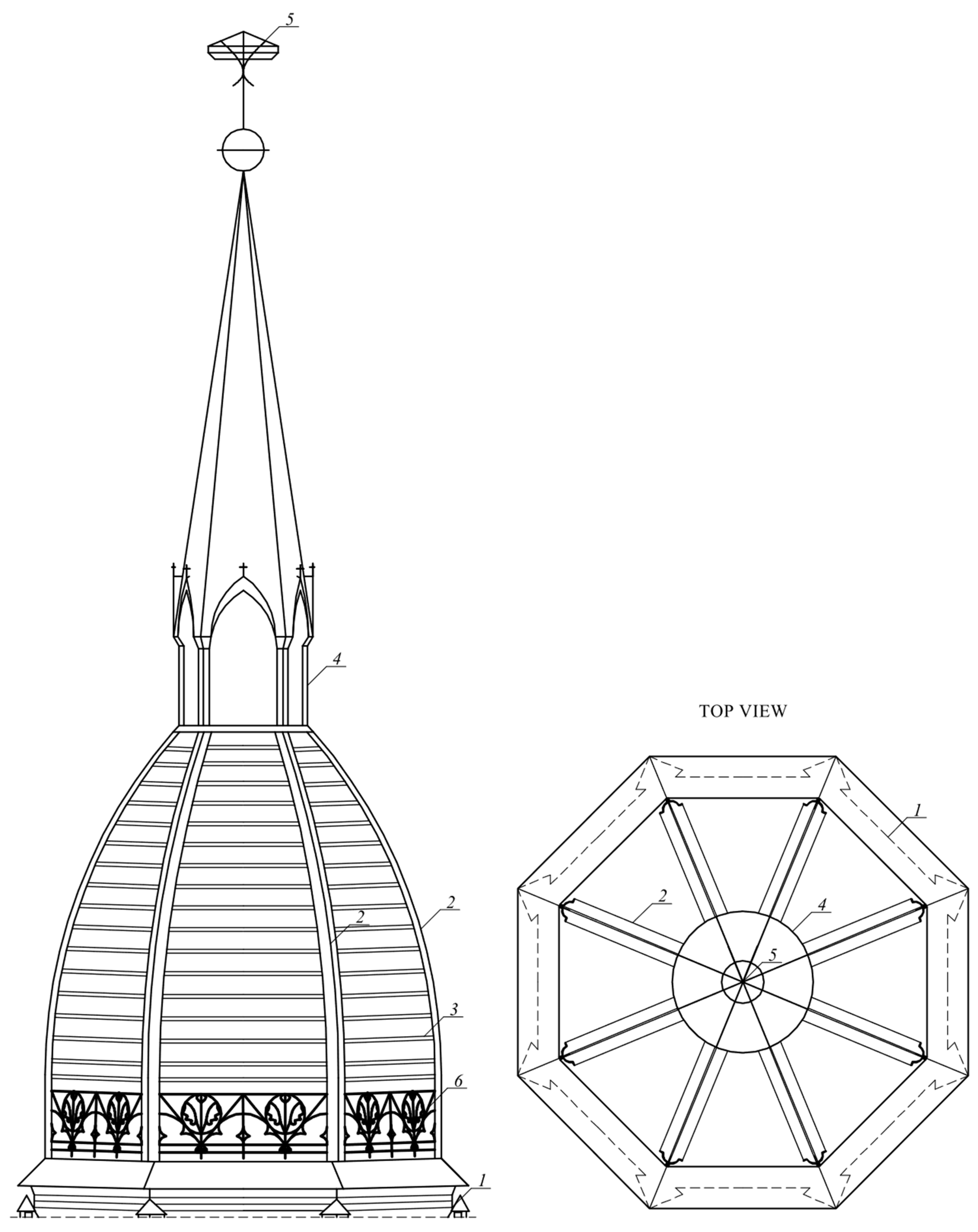
2. Case Study
2.1. Historical Background
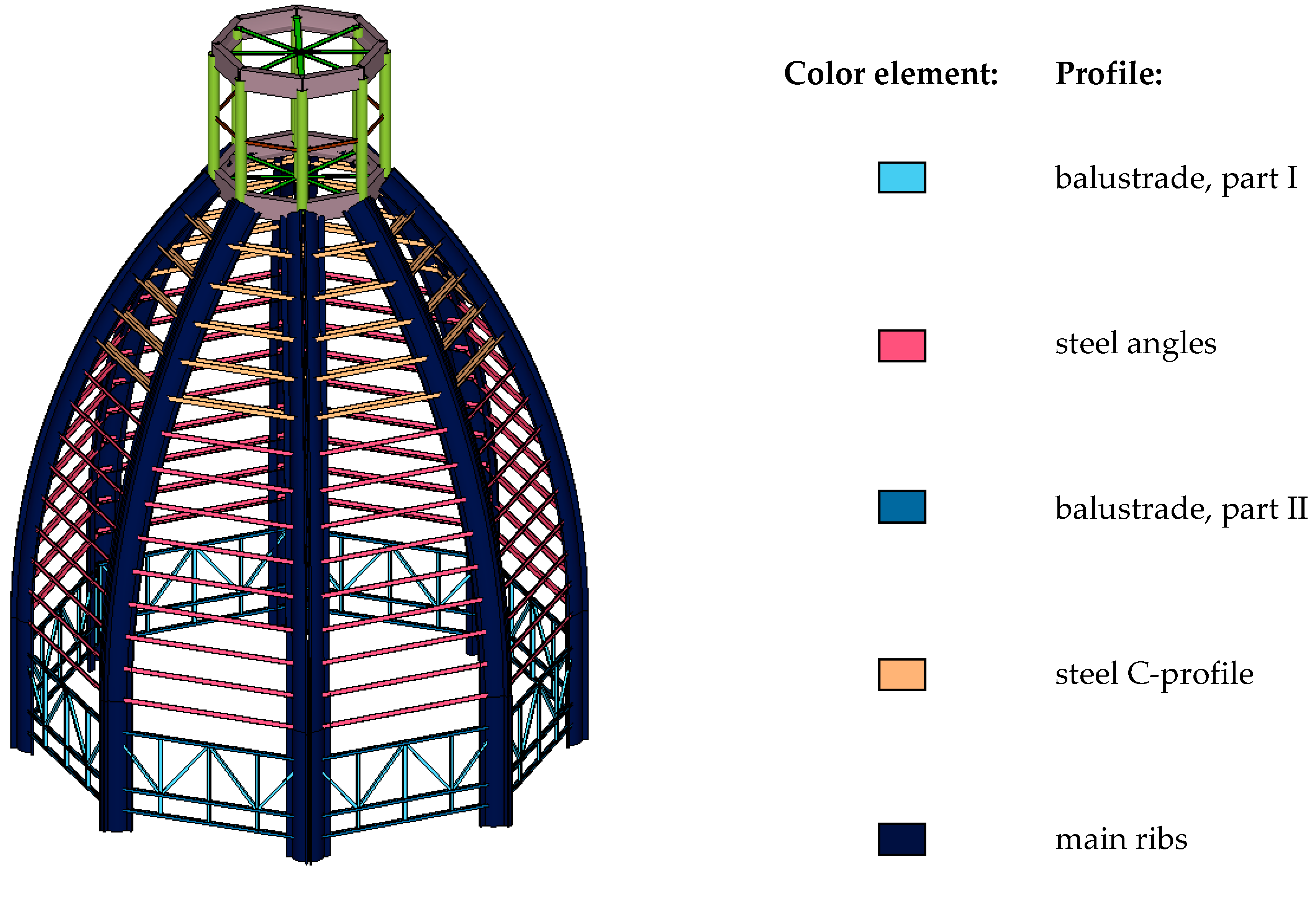
2.2. Architectural Values and Building Structure
3. The Technical Condition and Diagnostic Methods
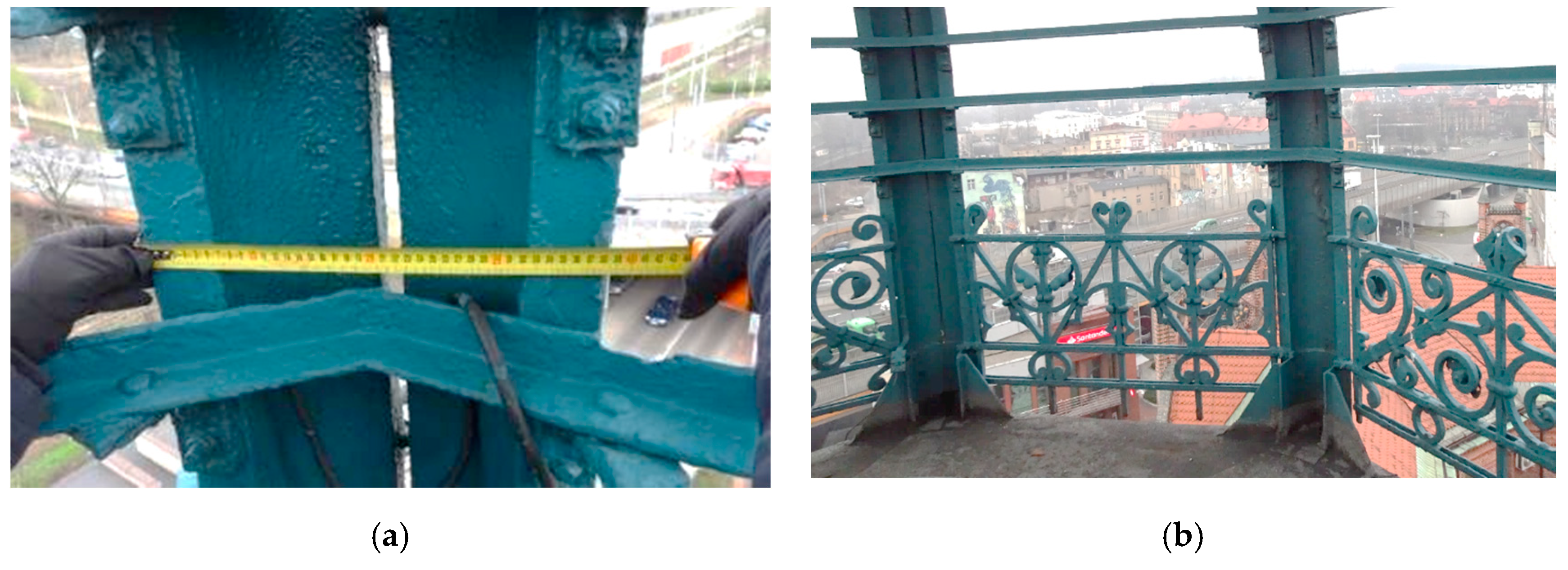
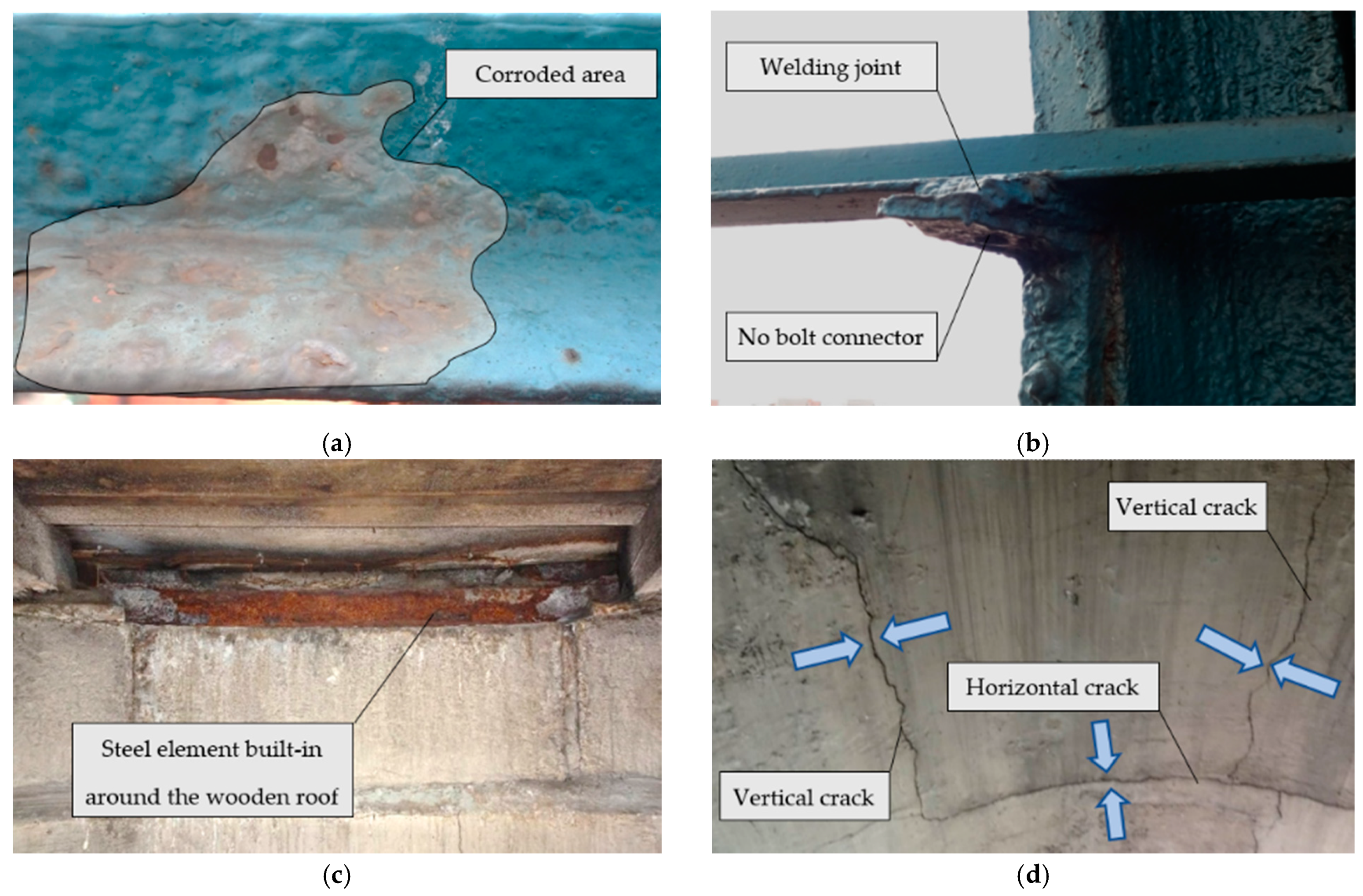
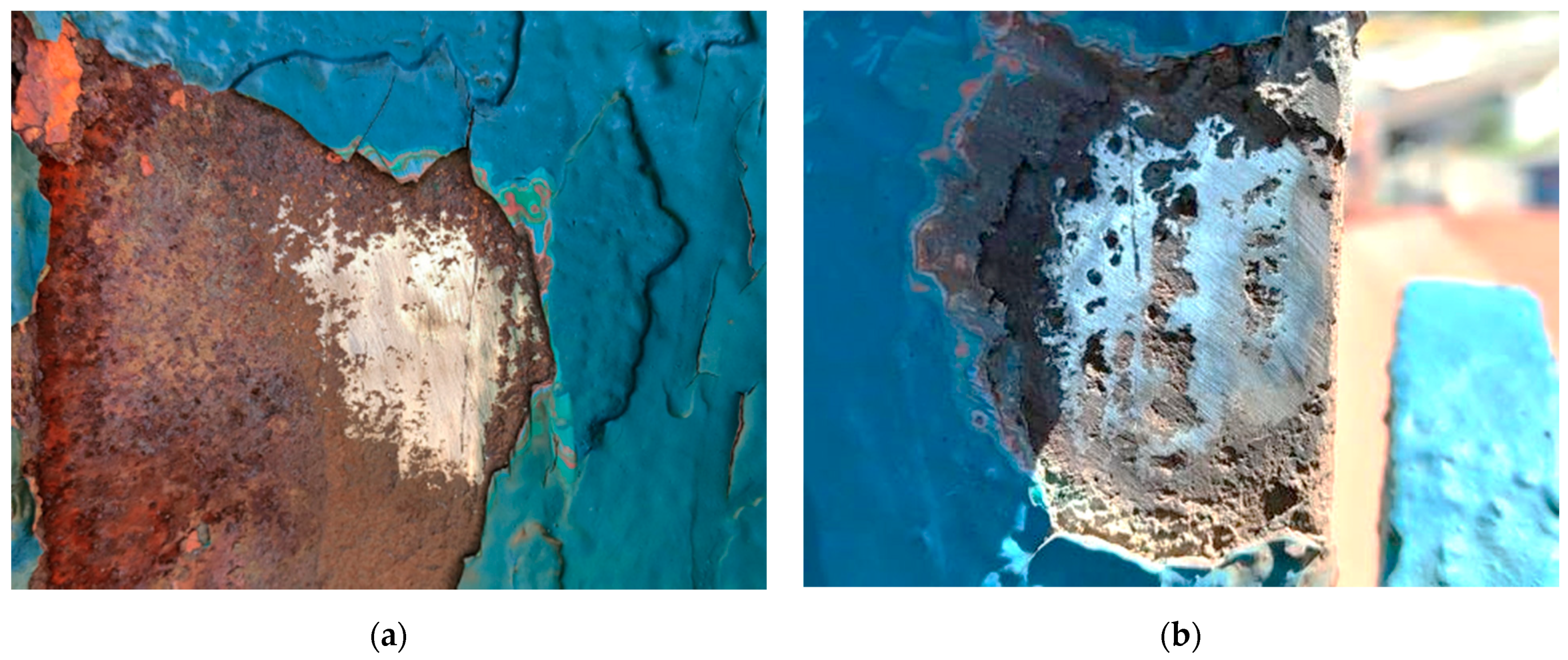
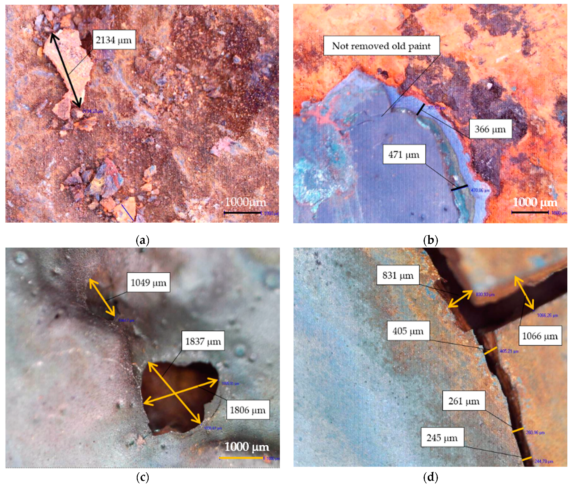
3.1. Macroscopically Observed Abnormalities
3.2. Non-Invasive Structure Diagnostics and Calculations
4. Results
4.1. Results of Non-Destructive Testing
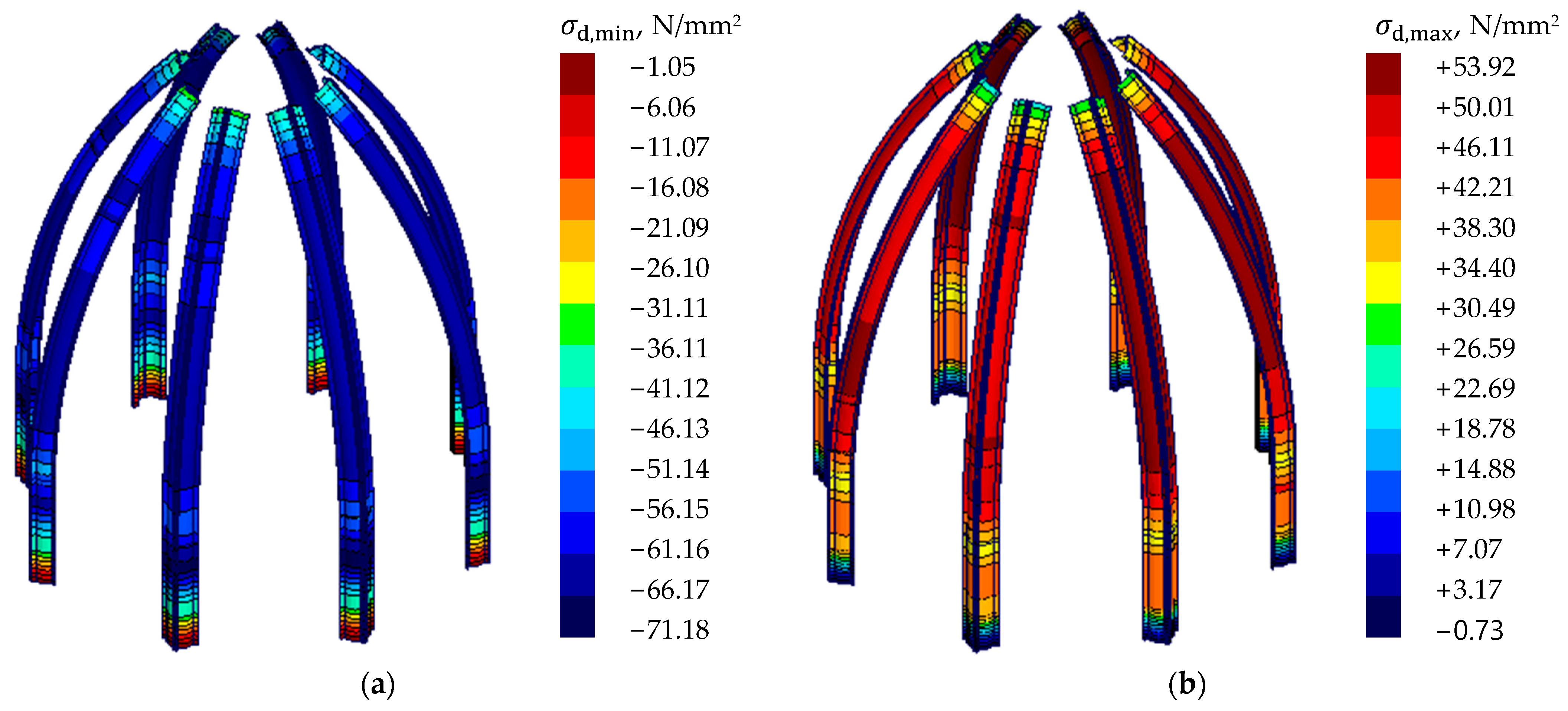
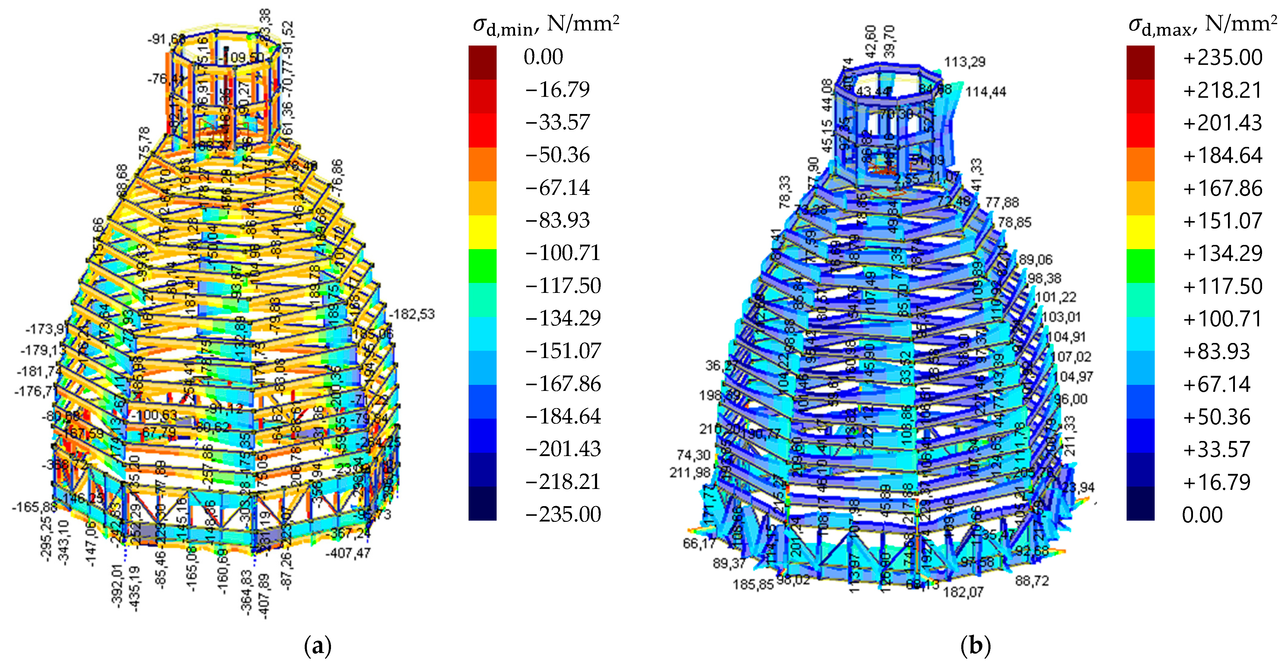
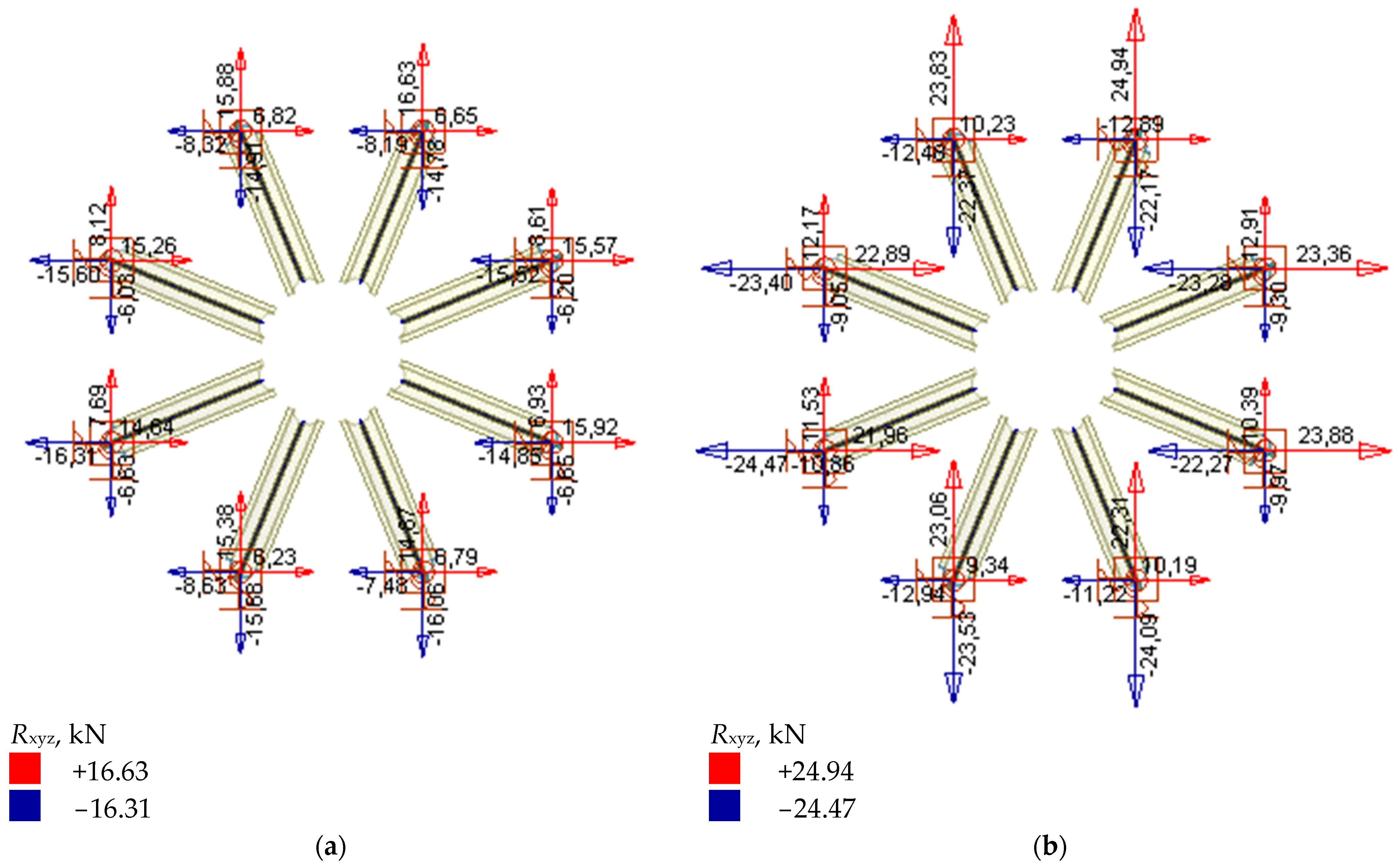
4.2. Results of Calculations
5. Discussion and Conclusions
Author Contributions
Funding
Institutional Review Board Statement
Data Availability Statement
Acknowledgments
Conflicts of Interest
References
- Ruggiero, G.; Marmo, R.; Nicolella, M. A Methodological Approach for Assessing the Safety of Historic Buildings’ Façades. Sustainability 2021, 13, 2812. [Google Scholar] [CrossRef]
- Rodrigues, F.; Matos, R.; Di, M.; Costa, A. Conservation level of residential buildings: Methodology evolution. Constr. Build. Mater. 2018, 172, 781–786. [Google Scholar] [CrossRef]
- Huynh, T.; Nguyen, B.-P.; Pradhan, A.M.S.; Pham, Q.-Q. Vision-based inspection of bolted joints: Field evaluation on a historical truss bridge in Viet Nam. Vietnam. J. Mech. 2020, 36, 77. [Google Scholar] [CrossRef]
- Borri, A.; Corradi, M. Architectural Heritage: A Discussion on Conservation and Safety. Heritage 2019, 2, 631–647. [Google Scholar] [CrossRef] [Green Version]
- Du, F.; Okazaki, K.; Ochiai, C.; Kobayashi, H. Post-disaster building repair and retrofit in a disaster-prone historical village in China: A case study in Shangli, Sichuan. Int. J. Disaster Risk Reduct. 2016, 16, 142–157. [Google Scholar] [CrossRef]
- Nowogónska, B. Consequences of Abandoning Renovation: Case Study—Neglected Industrial Heritage Building. Sustainability 2020, 12, 6441. [Google Scholar] [CrossRef]
- Drobiec, Ł.; Grzyb, K.; Zając, J. Analysis of reasons for the structural collapse of historic buildings. Sustainability 2021, 13, 10058. [Google Scholar] [CrossRef]
- Cardani, G.; Belluco, P. Reducing the Loss of Built Heritage in Seismic Areas. Buildings 2018, 8, 19. [Google Scholar] [CrossRef] [Green Version]
- Yi, J.; Park, W.; Lee, S.; Huynh, T.; Kim, J.; Seo, C. Evaluation of Vibration Characteristics of an Existing Harbor Caisson Structure Using Tugboat Impact Tests and Modal Analysis. Int. J. Ofdistributed Sens. Netw. 2013, 2013, 1–11. [Google Scholar] [CrossRef] [Green Version]
- Balayssac, J.-P.; Garnier, V. (Eds.) Non-Destructive Testing and Evaluation of Civil Engineering Structures; Elsevier Science: Amsterdam, The Netherlands, 2017; ISBN 9780081023051. [Google Scholar]
- Ramesh, G.; Srinath, D.; Ramya, D.; Vamshi Krishna, B. Repair, rehabilitation and retrofitting of reinforced concrete structures by using non-destructive testing methods. Mater. Today Proc. 2021, in press. [Google Scholar] [CrossRef]
- Reddy, K.A. Non-Destructive Testing, Evaluation Of Stainless Steel Materials. Mater. Today Proc. 2017, 4, 7302–7312. [Google Scholar] [CrossRef]
- Deepak, J.R.; Raja, V.K.B.; Srikanth, D.; Surendran, H.; Nickolas, M.M. Non-destructive testing (NDT) techniques for low carbon steel welded joints: A review and experimental study. Mater. Today Proc. 2021, 44, 3732–3737. [Google Scholar] [CrossRef]
- TÜV Rheinland. Non-Destructive Testing Methods. Available online: https://www.tuv.com/poland/pl/lp/tuv-rheinland-academy/main-navigation/training/szkolenia-w-polsce/badania-nieniszczące/?wt_mc=SEA.Ads.Google.PL22_A02_NDT.PL22_A02_NDT_GA.textad.google_ads_ndt&cpid=PL22_A02_NDT_GA (accessed on 21 June 2022).
- Ghosh, N.; Kumar, P.; Nandi, G. Parametric Optimization of MIG Welding on 316L Austenitic Stainless Steel by Grey-Based Taguchi Method. Procedia Technol. 2016, 25, 1038–1048. [Google Scholar] [CrossRef] [Green Version]
- Diagnostyka Techniczna-Badania. Non-Destructive Testing of Steel Materials and Their Connections. Available online: http://www.dt-b.pl/badania-nieniszczace-materialow-stalowych-i-ich-polaczen (accessed on 21 June 2022).
- DRACO Laboratorium Badań Nieniszczących. Visual Method. Available online: https://www.draco.com.pl/en/our-offer/visual-method-vt (accessed on 5 July 2022).
- Chen, B.; Wang, C.; Wang, P.; Zheng, S.; Sun, W. Research on Fatigue Damage in High-Strength Steel (FV520B) Using Nonlinear Ultrasonic Testing. Shock. Vib. 2020, 2020, 8847704. [Google Scholar] [CrossRef]
- Xu, X.; Mi, G.; Xiong, L.; Jiang, P.; Shao, X.; Wang, C. Morphologies, microstructures and properties of TiC particle reinforced Inconel 625 coatings obtained by laser cladding with wire. J. Alloy. Compd. 2018, 740, 16–27. [Google Scholar] [CrossRef]
- Chen, L.; Yuan, F.P.; Jiang, P.; Wu, X.L. Mechanical properties and nanostructures in a duplex stainless steel subjected to equal channel angular pressing. Mater. Sci. Eng. A 2012, 551, 154–159. [Google Scholar] [CrossRef] [Green Version]
- Walley, S.M. Historical origins of indentation hardness testing. Mater. Sci. Technol. 2012, 28, 1028–1044. [Google Scholar] [CrossRef]
- Kennedy, J.R.; Wiskel, J.B.; Ivey, D.G.; Henein, H. L80 pipe steel microstructure assessment using ultrasonic testing. Mater. Sci. Technol. 2019, 35, 1942–1949. [Google Scholar] [CrossRef]
- Fydrych, D.; Łabanowski, J.; Rogalski, G.; Haras, J.; Tomków, J.; Świerczyńska, A.; Jakóbczak, P.; Kostro, Ł. Weldability of S500MC Steel in Underwater Conditions. Adv. Mater. Sci. 2014, 14, 37–45. [Google Scholar] [CrossRef] [Green Version]
- Chandler, H. Hardness Testing; ASM International: Almere, The Netherlands, 1999. [Google Scholar]
- emcoTEST. Principles of Hardness Testing. Hardness Testing—A Material Testing Method. Available online: https://www.emcotest.com/en/the-world-of-hardness-testing/hardness-know-how/theory-of-hardness-testing/principles-of-hardness-testing-54/hardness-testing-a-material-testing-method-230/ (accessed on 16 September 2022).
- Navitest. Hardness Testing. Available online: https://navitest.com.pl/pl/badania-nieniszczace/badania-twardosci/ (accessed on 2 July 2022).
- Useinov, A.; Gogolinskiy, K.; Reshetov, V. Mutual consistency of hardness testing at micro- and nanometer scales. Int. J. Mater. Res. 2009, 100, 968–972. [Google Scholar] [CrossRef]
- Huber, N.; Heerens, J. On the effect of a general residual stress state on indentation and hardness testing. Acta Mater. 2008, 56, 6205–6213. [Google Scholar] [CrossRef] [Green Version]
- Srivastava, K.; Sinha, A.A.; Sahani, R. Effect of heat treatment on hardness and toughness of EN8 steel. Mater. Today Proc. 2020, 42, 1297–1303. [Google Scholar] [CrossRef]
- Nakahata, K.; Hirose, S.; Schubert, F.; Köhler, B. Image Based EFIT Simulation for Nondestructive Ultrasonic Testing of Austenitic Steel. J. Solid Mech. Mater. Eng. 2009, 3, 1256–1262. [Google Scholar] [CrossRef] [Green Version]
- Navitest. Ultrasonic Thickness Measurements. Available online: https://navitest.com.pl/pl/badania-nieniszczace/ultradzwiekowe-pomiary-grubosci-uttutm/ (accessed on 28 June 2022).
- Texas Nondestructive Testing Academy. Ultrasonic Testing. Advantages & Disadvantages. Available online: https://www.txndt.com/safety-section/ultrasonic-testing (accessed on 16 September 2022).
- DRACO Laboratorium Badań Nieniszczących. Ultrasonic Thickness Testing. Available online: https://www.draco.com.pl/en/our-offer/ultrasonic-thickness-testing-utt (accessed on 5 July 2022).
- DRACO Laboratorium Badań Nieniszczących. Ultrasonic Leak Testing. Available online: https://www.draco.com.pl/en/our-offer/ultrasonic-leak-testing-lt (accessed on 5 July 2022).
- Navitest. Ultrasonic Leak Testing. Available online: https://navitest.com.pl/pl/badania-nieniszczace/ultradzwiekowe-pomiary-szczelnosci/ (accessed on 5 July 2022).
- DRACO Laboratorium Badań Nieniszczących. Ultrasonic Tests Phased Array. Available online: https://www.draco.com.pl/en/our-offer/ultrasonic-tests-phased-array-pa (accessed on 5 July 2022).
- Chassignole, B.; Duwig, V.; Ploix, M.A.; Guy, P.; El Guerjouma, R. Modelling the attenuation in the ATHENA finite elements code for the ultrasonic testing of austenitic stainless steel welds. Ultrasonics 2009, 49, 653–658. [Google Scholar] [CrossRef] [PubMed]
- DRACO Laboratorium Badań Nieniszczących. Time of Flight Diffraction. Available online: https://www.draco.com.pl/en/our-offer/time-of-flight-diffraction-tofd (accessed on 5 July 2022).
- Lin, Z.B.; Azarmi, F.; Al-Kaseasbeh, Q.; Azimi, M.; Yan, F. Advanced Ultrasonic Testing Technologies with Applications to Evaluation of Steel Bridge Welding—An Overview. Appl. Mech. Mater. 2015, 727–728, 785–789. [Google Scholar] [CrossRef]
- Navitest. Ultrasonic Testing. Available online: https://navitest.com.pl/pl/badania-nieniszczace/badania-ultradzwiekowe/ (accessed on 28 June 2022).
- Dombret, P. Methodology for the ultrasonic testing of austenitic stainless steel. Nucl. Eng. Des. 1991, 131, 279–284. [Google Scholar] [CrossRef]
- Thorat, S.; Non Destructive Testing. NDT Testing. Procedure Of NDT. Available online: https://learnmech.com/non-destructive-testing-ndt-testing-procedure-of-ndt/ (accessed on 16 September 2022).
- Dwivedi, S.K.; Vishwakarma, M.; Soni, P.A. Advances and Researches on Non Destructive Testing: A Review. Mater. Today Proc. 2018, 5, 3690–3698. [Google Scholar] [CrossRef]
- Liu, H.; Chen, Z.; Zhou, T. Investigation on temperature distribution and thermal behavior of large span steel structures considering solar radiation. Adv. Steel Constr. 2013, 9, 41–58. [Google Scholar]
- Lien, K.H.; Chiou, Y.J.; Wang, R.Z.; Hsiao, P.A. Nonlinear behavior of steel structures considering the cooling phase of a fire. J. Constr. Steel Res. 2009, 65, 1776–1786. [Google Scholar] [CrossRef]
- Liu, H.; Chen, Z.; Zhou, T. Theoretical and experimental study on the temperature distribution of H-shaped steel members under solar radiation. Appl. Therm. Eng. 2012, 37, 329–335. [Google Scholar] [CrossRef]
- Becker, R. Structural behavior of simple steel structures with non-uniform longitudinal temperature distributions under fire conditions. Fire Saf. J. 2002, 37, 495–515. [Google Scholar] [CrossRef]
- Liu, H.; Chen, Z.; Chen, B.; Xiao, X.; Wang, X. Studies on the temperature distribution of steel plates with different paints under solar radiation. Appl. Therm. Eng. 2014, 71, 342–354. [Google Scholar] [CrossRef]
- Sun, R.; Huang, Z.; Burgess, I.W. Progressive collapse analysis of steel structures under fire conditions. Eng. Struct. 2012, 34, 400–413. [Google Scholar] [CrossRef] [Green Version]
- Outinen, J.; Makelainen, P. Mechanical properties of structural steel at elevated temperatures and after cooling down. Fire Mater. 2004, 28, 237–251. [Google Scholar] [CrossRef]
- Leroy, C.; Alvaro, A.; Maljaars, J. The effect of low temperatures on the fatigue crack growth of S460 structural steel. Int. J. Fatigue 2016, 82, 110–118. [Google Scholar] [CrossRef]
- Paik, J.K.; Kim, B.J.; Park, D.K.; Jang, B.S. On quasi-static crushing of thin-walled steel structures in cold temperature: Experimental and numerical studies. Int. J. Impact Eng. 2011, 38, 13–28. [Google Scholar] [CrossRef]

| NDT Methods | Advantages | Limitations |
|---|---|---|
| Visual testing |
|
|
| Hardness testing |
|
|
| Ultrasonic testing |
|
|
| Tested Steel Angle | Element 1 | Element 2 | Element 3 |
|---|---|---|---|
| Measured thickness range | 5.98–6.00 mm | 4.75–5.38 mm | 5.65–5.67 mm |
| Average thickness | 5.99 mm | 5.31 mm | 5.66 mm |
| Corrosive loss | 1% | 11% | 6% |
| Maximum Stress, σd,max | Minimum Stress, σd,min | Stress-Strain State, |σd|/fyd |
|---|---|---|
| 53.92 N/mm2 | - | 0.23 |
| - | −71.18 N/mm2 | 0.30 |
Publisher’s Note: MDPI stays neutral with regard to jurisdictional claims in published maps and institutional affiliations. |
© 2022 by the authors. Licensee MDPI, Basel, Switzerland. This article is an open access article distributed under the terms and conditions of the Creative Commons Attribution (CC BY) license (https://creativecommons.org/licenses/by/4.0/).
Share and Cite
Grzyb, K.; Drobiec, Ł.; Blazy, J.; Zając, J. The Use of NDT Diagnostic Methods and Calculations in Assessing the Masonry Tower Crowned with the Steel Dome. Materials 2022, 15, 7196. https://doi.org/10.3390/ma15207196
Grzyb K, Drobiec Ł, Blazy J, Zając J. The Use of NDT Diagnostic Methods and Calculations in Assessing the Masonry Tower Crowned with the Steel Dome. Materials. 2022; 15(20):7196. https://doi.org/10.3390/ma15207196
Chicago/Turabian StyleGrzyb, Krzysztof, Łukasz Drobiec, Julia Blazy, and Jakub Zając. 2022. "The Use of NDT Diagnostic Methods and Calculations in Assessing the Masonry Tower Crowned with the Steel Dome" Materials 15, no. 20: 7196. https://doi.org/10.3390/ma15207196