Abstract
The through-plane permeability is of great importance for understanding the transport phenomenon in anisotropic fibrous porous material. In this paper, a novel pore-scale model based on the equilateral triangle representative unit cell (RUC) and capillary bundle model is developed for the fluid flow through the anisotropic fibrous porous material according to fractal theory, and the effective through-plane permeability is presented accordingly. The digital structures of the fibrous porous material are generated by a fractal stochastic method (FSM), and the single-phase fluid flow through the 3D-reconstructed model is simulated by using the finite element method (FEM). It was found that the effective through-plane permeability depends on the fiber column size, porosity, and fractal dimensions for pore and tortuosity. The results show that the predicted through-plane permeability by the present fractal model indicates good agreement with numerical results and available experimental data as well as empirical formulas. The dimensionless through-plane permeability is positively correlated with the porosity and negatively correlated with the fractal dimensions for pore and tortuosity at certain porosity.
1. Introduction
Fibrous porous materials with advantages such as high specific area, high thermal conductivity, and good flexibility, etc., have been widely applied in textile fabric, fuel cells, filtration, and acoustic engineering, etc. [1,2]. Meanwhile, the conducting properties of fibrous porous material, including thermal conductivity and permeability as well as diffusion coefficient, strongly depend on its complex microstructures. Therefore, the characterization and reconstruction of microstructure and transport properties of fibrous porous material have attracted broad interests from multi-discipline fields [3,4,5].
Recently, with the development of computational technology, a few numerical reconstruction methods, including simulated annealing method (SAM) [6], Markov chain Monte Carlo (MCMC) [7], Bayesian reconstruction method (BRM) [8], random generation-grow method (RGGM) [9], multiple-point statistics method (MPSM) [10], etc., have been proposed to generate the digital structure of fibrous porous material, and a variety of simulation methods such as pore network modeling (PNM) [11], lattice Boltzmann method (LBM) [12], direct simulation Monte Carlo method (DSMC) [13], finite element method (FEM) [14], etc., have been applied to study the transport properties and mechanisms of fibrous porous material. Xie et al. [15] proposed a random-number-based algorithm to reconstruct the structure of fibrous silica aerogel and predicted its thermal conductivity by using discrete ordinate method and finite volume method (FVM). Hosseinalipour and Namazi [16] proposed a reconstruction algorithm based on the fiber orientation and explored the effect of geometric parameters of fibrous porous material on its transport property by FEM. Xu et al. [17] combined SAM with a hybrid function of two-point correlation function and lineal-path function as well as co-occurrence correlation function to reconstruct the 3D microstructures of two-phase fiber-pore hand sheets and simulated the absolute permeability based on computational fluid dynamics (CFD). Shi et al. [18] used stochastic orientation method to generate the fibrous structure of gas diffusion layer (GDL) and simulated the transport behavior of gas–liquid two-phase through the GDL by the volume of fluid (VOF) method. In order to explain why the transverse permeability of the fibrous porous material increases with the increase of through-plane angle of fibers, Pradhan et al. [19] generated a series of 3D fibrous structure by using the voxel model and calculated the transverse permeability by solving Stokes flow equations. Gostick [20] presented a novel algorithm to reconstruct pore networks from 3D fibrous porous material by using standard image analysis techniques and obtained the anisotropic permeability with a PNM tool. Wang et al. [21] developed a quartet structure generation set (QSGS) method to reconstruct the micro morphology of fibrous porous material and calculated the effective thermal conductivity based on LBM. Zhang et al. [22] proposed a novel algorithm based on the geometrical information of scanning electron microscopic (SEM) images to reconstruct the structure of carbon fiber and simulated the flow properties by using LBM. Caglar et al. [23] developed a computation approach for the permeability of the 3D fibrous porous material based on the circuit analogy and deep learning to speed up numerical computation.
Nonetheless, given that the geometrical characteristic is a major determining factor in transportation, it is necessary to accurately characterize the microstructures of fibrous porous material. However, it is difficult to represent and reconstruct the complex and multiscale structures of fibrous porous media based on Euclidean geometry. Since a great deal of experiments show that the microstructures of the fibrous porous material indicate statistically fractal scaling laws [24,25,26], a few fractal models such as self-similar Sierpinski carpet [27], fractal capillary model [28], Weierstrass–Mandelbrot (W-M) model [29], etc., have been proposed to study the transport properties of the fibrous porous material. Xu et al. [30] developed a pore-scale physical model based on the pore fractal scaling law and predicted the two-phase relative permeability in unsaturated porous media by Monte Carlo simulation. Zhu et al. [31] developed a fractal model for the power-law fluids in fibrous porous material with consideration of electrokinetic effect and calculated the permeability by solving linearized Poisson–Boltzmann and Navier–Stokes equations. Xiao et al. [32] proposed a fractal solution for the Kozeny–Carman (KC) constant and permeability of the fibrous porous material, which is made up by solid particles and porous fibers. Xu et al. [33] developed a simple multi-scale mathematical method by synthesizing the implicit periodic surface model and the W-M fractal model to reconstruct the 3D structure of porous metal fiber sintered felt and discussed the effects of the surface topography and fractal dimension on the gas permeability. Shou et al. [34] proposed a difference-fractal model for the permeability of viscous flow through fibrous porous material by using difference approach and proved that the permeability greatly depends on the maximum pore scale.
Although fractal geometry theory has been proposed to study the fluid flow through the fibrous porous material, the relevant parameters, including fiber orientation, anisotropic, flow tortuosity, etc., still need to be adjusted based on the specific fibrous structures [35,36,37]. Therefore, in order to address these deficiencies, a new pore-scale model based on fractal geometry is explained in this paper to derive the through-plane permeability of anisotropic fibrous porous material, where an equilateral triangle RUC and the capillary bundle model are combined. In addition, the analytical expression of the average tortuosity in fibrous porous material is presented based on two kinds of representative distribution structure (RDS) of fiber columns. A numerical reconstruction method is also proposed to generate the 3D random structures of fibrous porous material by fractal stochastic method (FSM), and the single-phase fluid flow through transversely isotropic random fibrous porous material was simulated by using the FEM.
2. Fractal Model
The random size and distribution of pores in fibrous porous material generally led to two possible flow directions: in-plane and through-plane flow [38]. Thereinto, the through-plane flow through fibrous porous material is an essential phenomenon [39], which has attracted considerable attention [40,41,42]. Thus, a pore-scale fractal model was developed in order to obtain the analytical expression of effective through-plane permeability in this part.
2.1. Pore-Scale Model
The rectangular fiber RUC model for fibrous porous media was proposed by Plessis [43]. It is the smallest unit cell but illustrates the average geometrical properties of a representative elementary volume (REV) [44,45]. A pore-scale model (Figure 1a) for the through-plane flow through an anisotropic fibrous porous material was firstly developed. Different from the rectangular RUC model [46], an equilateral triangle RUC model that is more realistic is proposed to determine the pore size of the fibrous material. It can be seen from the SEM image (Figure 1b) of a fibrous porous material REV that there is a large number of triangular pores with different sizes, and these triangular pores are formed by fiber columns with stochastic length and direction in parallel planes (Figure 1d). The equilateral triangle RUC model (Figure 1e) is assumed in each layer of fibrous porous material. The representative and actual length of the through-plane flow capillary are L0 and Lt, as shown in Figure 1c, and the symbols λ and d represent the pore size and the diameter of fiber column, respectively.
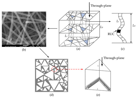
Figure 1.
Pore-scale model: (a) 3D REV model; (b) SEM image; (c) flow capillary; (d) stochastic triangle pores; (e) equilateral triangle RUC model.
2.2. Fractal Pore
The pores in fibrous porous material have been proven to show statistically fractal scaling laws [24,25,26], and for simplicity, the pores of model are considered to be ideal spherical pores in fibrous porous material [47]. Thus, the size distribution of the spherical pores in a 3D REV model (Figure 1a) is assumed to follow the fractal probability density function (PDF) [48]:
where represents the minimum pore size. The fractal dimension of pore Df can be determined by [48]
where is the bulk porosity, is the maximum pore size, and the Euclidean dimension dE is 2 and 3, respectively, for the two-dimensional plane and three-dimensional space. The mean pore size of fibrous porous material in the 3D space can be calculated as follows:
where the range of pore fractal dimension in a 2D plane (Df) is [1,2], and the fractal criterion was used because the fractal PDF satisfies normalizing condition. Thus, the total pore volume in fibrous porous material can be calculated as follows:
In an REV, the bulk porosity can be expressed as . Then, according to Equation (4), the representative length is obtained as
As shown in Figure 1d, the random fiber columns determine the shape of staked fiber layers and can be approximated as equilateral triangles on the cross-sectional area perpendicular to through-plane flow direction. Therefore, the total pore area perpendicular to through-plane flow can be calculated as
where is the surface porosity. The surface porosity in Equation (6) is taken as equal to the bulk porosity in Equation (2), and the cross-sectional area in an REV is . The maximum pore volume can be expressed as
where is the total volume. Since the RUC can represent the averaged geometrical properties of an REV [45], the volume of fibers in the maximum pore can be written as . Based on fractal geometry theory, the shapes of pores with different size in fibrous porous material are similar. Therefore, the largest pore volume corresponds to the maximum pore size. The maximum pore size on the cross-sectional area perpendicular to through-plane flow direction can be deduced from Equation (7):
2.3. Fractal Tortuosity
As shown in Figure 1a,c, the through-plane flow paths can be represented as a bundle of capillaries. The tortuous length of capillaries can be characterized by the fractal scaling law [49]:
where DT is the tortuosity fractal dimension and can be written as
where is the averaged tortuosity in a porous medium. Since the tortuosity is usually employed to characterize the conducting properties of porous media [50,51], two kinds of RDS of fiber columns were proposed to determine the tortuosity. As shown in Figure 2, the square arrangement (saRDS) and triangular arrangement (taRDS) were used here. The size pore and fiber column are λ and d, respectively. According to the definition of tortuosity [52] and saRDS in Figure 2a, the tortuosity of streamline 1 is , and the tortuosity of streamline 2 is . Because the proportion of the straight streamlines decreases, and the proportion of the curved streamlines increases with the increase of fiber column diameter, the averaged tortuosity of saRDS can be obtained by a weighted average of all possible streamlines [53], where is the weight value, and is the tortuosity of the ith streamline (i = 1, 2, 3, …, n). Therefore, the average tortuosity of saRDS is calculated as follows:
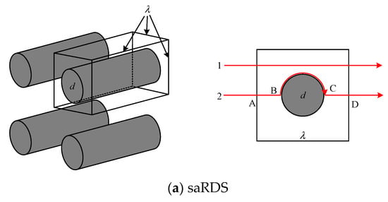
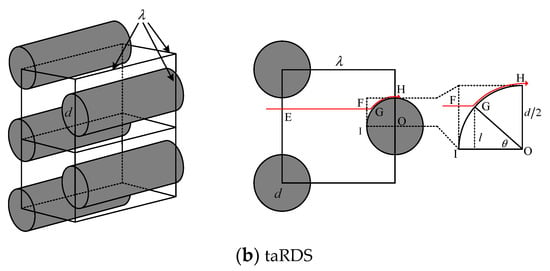
Figure 2.
The representative distribution structures of fiber columns: (a) square arrangement; (b) triangular arrangement.
Based on the weight-average method and taRDS shown in Figure 2b, the averaged tortuosity of taRDS can be expressed as
where . The tortuosity of streamline FGH is given by [54]:
where is the angle ∠GOI in Figure 2b. Then, the expression for the tortuosity in dotted box is , and the result of is calculated by integrating over .
Therefore, the tortuosity of taRDS is obtained as
The pores are randomly distributed in fibrous porous material, and the percentage of the square arrangement was assumed to be the same as that of the triangular arrangement. Then, the average tortuosity of RDS can be deduced from Equations (11) and (15) as follows:
Based on the fractal scaling law of pore (Equation (1)), the averaged tortuosity of an REV can be written as follows:
The averaged pore size can be estimated by the RDS. The pore volume of the RDS is , while the total volume of the RDS is . The porosity of the RDS is . Therefore, the ratio of fiber size to averaged pore size is
By combining Equations (3), (17) and (18), the averaged tortuosity can be expressed as
Then, the fractal dimension for tortuosity is obtained by combining Equations (10) and (19) as
2.4. Through-Plane Permeability
The single-phase fluid-flow rate through a curved capillary in fibrous porous material is assumed to satisfy the modified Hagen–Poiseuille equation:
where is the shape factor of the fluid through equilateral triangle capillaries [55], is the pore size, is the fluid viscosity, is the pressure drop along the capillary, and Lt is actual length of curved capillary. Therefore, based on Equations (1) and (9), the total flow rate of through-plane flow through the fibrous porous material can be calculated as follows:
where is the total number of pores in a cross-sectional area in an REV. According to Darcy’s law , the effective through-plane permeability can be expressed as
Inserting Equations (5), (6), (8), (18) and (20) into (23), the dimensionless through-plane permeability of an anisotropic fibrous porous material is obtained as
It can be found from Equation (24) that the through-plane permeability depends on both fiber column and pore structure; it is a function of fiber column size, porosity, and fractal dimensions for pore and tortuosity. The derivation details of pore size and tortuosity are provided in Appendix A.1 and Appendix A.2, respectively.
3. Numerical Simulation
A FSM was developed to numerically reconstruct the microstructure of the fibrous porous material, and the single-phase fluid flow through the digital 3D fibrous porous material was studied by FEM. The effective through-plane permeability calculated by the numerical simulation was compared to that by Equation (24) in order to verify the accuracy of the proposed fractal model in Section 2. The procedures for the reconstruction and simulation of 3D random fibrous porous material are illustrated in Figure 3.
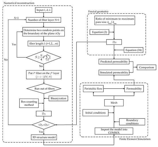
Figure 3.
Flowchart of fractal reconstruction and FEM simulation.
The following assumptions were established in the reconstruction by FSM: (1) fiber columns are cylinders with uniform diameter that are also straight and infinite in length; (2) fiber columns in the same layer are allowed intersection while touching but not intersecting between layers; (3) fiber layers are stacked along the z-direction, and each fiber layer is parallel to the plane xOy.
The procedures of FSM include: (1) input REV size L, fiber column diameter d, and porosity and calculate the fractal dimension of cross-sectional pore Df,b based on Equation (2); (2) start the number of fiber layers from N = 1; (3) select two random points on the boundary of the plane xOy and generate a cylindrical fiber column, then calculate the fiber column length li (i = 1, 2, 3, …, m) and measure the fiber volume by until it reaches the value of ; (4) put ith (i = 1, 2, 3, …, m) fiber column on the jth layer (); (5) binarize the cross-sectional area obtained in Step 4 and use box-counting method to calculate the fractal dimension of cross-sectional Df,a; (6) return to Step 2 and set the number of fiber layers to N + 1 if ; (7) finish reconstruction process and output the 3D structural model of fibrous porous material. The reconstruction procedures of the concrete example of fibrous porous material are shown in Appendix A.3.
For the incompressible single-phase flow of Newtonian fluid in a 3D fibrous porous material, the governing equations are
where p, u, and represent the pressure, velocity field, and dynamic viscosity of the fluid, respectively. As shown in Figure 4, the pressure drop of 2 Pa is applied between inlet and outlet, and the symmetric boundary condition is used for other faces. The fluid dynamic viscosity and density are 0.001 kg/(m·s) and 1000 kg/m3, respectively. The peristaltic flow module in COMSOL Multiphysics was adopted, and the independency of grid density was also examined.
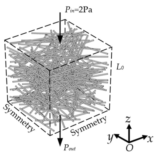
Figure 4.
The physical model of 3D fibrous porous material with boundary conditions.
In order to validate the present fractal model, the through-plane permeability by FEM under the same ratio of minimum to maximum of pore size () and the dimensionless permeability by fractal model (Equation (24)) were compared and are listed in Table 1. It should be noted that the through-plane permeability error between fractal model and numerical is within 5%, which indicates that the fractal model agrees well with numerical simulation.

Table 1.
Comparison between fractal model and numerical simulation ( ).
The predictions of the through-plane permeability by the present fractal model (Equation (24)) were also compared with available experimental data [56,57,58,59,60,61,62] and common empirical formulas [63,64,65]. As shown in Figure 5, the dimensionless through-plane permeability increases with increased porosity. It can be clearly seen in Figure 5 that the through-plane permeability by the present fractal model is in good agreement with available empirical formulas over the whole range of porosity. For the relative low porosity (), the present fractal model shows better agreement with experimental data compared with that of empirical formulas. However, at the relative high porosity (), the predicted through-plane permeability is slightly lower than that of the experimental data. It can be ascribed to the small number of fiber columns at high porosity, which induces the increases of the ratio of minimum to maximum pore size () of a 3D fibrous porous material and the in high porosity. Thus, the flow resistance of the present mathematical model is generally higher than that of the experimental data.
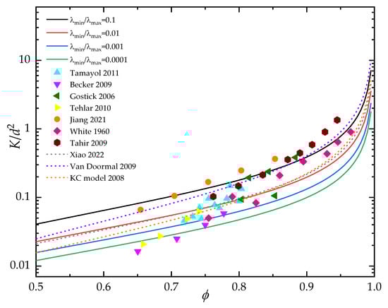
Figure 5.
Comparison of predicted through-plane permeability with available experiment data and empirical formulas [56,57,58,59,60,61,62,63,64,65].
4. Results and Discussion
Figure 6 shows the structure of 3D fibrous porous material with porosity of 0.95 and 0.90 by FSM and the velocity distribution on the cross-sectional area perpendicular to through-plane fluid flow by FEM simulation. Driven by the identical pressure drop, the pore spaces become more wide-open at high porosity, and the average velocity on the cross-sectional area is large. As the porosity decreases, the capillary tortuosity increases, and there is a certain blocking effect of fiber columns on fluid flow, resulting in lower and more uniform fluid velocity in the pore space.
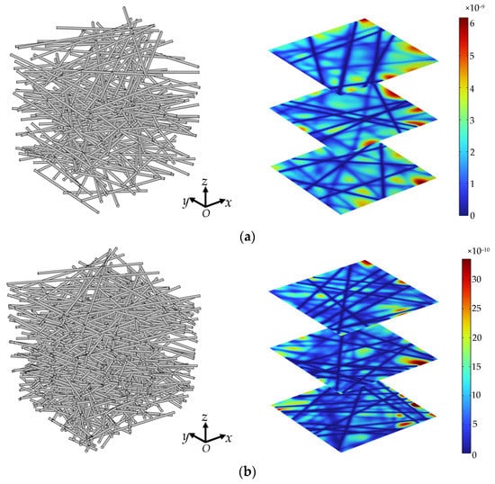
Figure 6.
3D structure and velocity distribution (m/s) of random fibrous porous material with different porosity: (a) ; (b) .
The influences of geometrical parameters on the dimensionless through-plane permeability of fibrous porous material were also examined. As shown in Figure 7, at certain pore size range (), the pore fractal dimension is positively correlated with the porosity, while the tortuosity fractal dimension is negatively correlated with the porosity. With the increase of pore size range (ratio of minimum to maximum pore size decreases), the pore structure becomes more complicated, and the portion of small pores increase. Thus, the pore and tortuosity fractal dimensions increase and decreases with the increase of pore size range under fixed porosity, respectively. It can be found in Figure 8 that the through-plane permeability decreases as the pore fractal dimension increases at certain porosity. This is because the complexity of the pores increases as the fractal dimension for pore distribution under fixed porosity, which induces the increase of flow resistance. As shown in Figure 9, the dimensionless through-plane permeability significantly decreases with the increase of tortuosity fractal dimension under certain pore size range. It can be explained as that the increased porosity reduces the likelihood of fiber columns’ intersection; thus, the tortuosity of fibrous porous material decreases with the increment of pore space. Meanwhile, the fiber columns in a 3D space generally increase the blocking effect on fluid flow with increased tortuosity fractal dimension, and when the pore size range increases (the value of decreases), more fiber columns with similar orientations are used to reconstruct the fibrous porous material. Therefore, the through-plane permeability decreases as the pore size range increases. It should be noted that the nonlinear phenomena in fluid flow through the fibrous material may have correlation with the anisotropic properties [66].
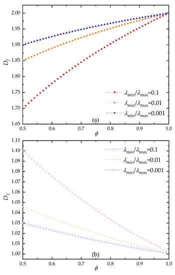
Figure 7.
The relationship between fractal dimension and porosity: (a) pore fractal dimension; (b) tortuosity fractal dimension.
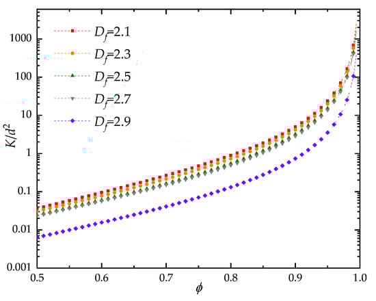
Figure 8.
The effect of pore fractal dimension on the dimensionless through-plane permeability of fibrous porous material.
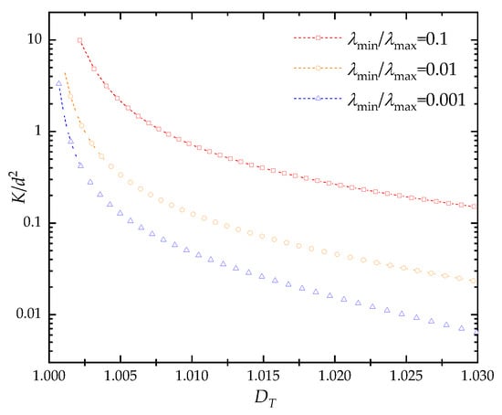
Figure 9.
The effect of tortuosity fractal dimension on the dimensionless through-plane permeability of fibrous porous material.
5. Conclusions
In this paper, by combining the equilateral triangle RUC model and fractal capillary bundle model, a new pore-scale model was developed to predict the effective through-plane permeability of the anisotropic fibrous porous materials, and a numerical reconstruction method is also proposed for the reconstructed 3D random structure of fibrous porous material. The analytical expressions for the effective through-plane permeability and average tortuosity were proposed, and the FEM was applied to study the flow field of the 3D anisotropic fibrous porous material generated by FSM. The proposed fractal model was validated by comparing with numerical simulation and available experimental as well as common empirical formulas. The results indicate that: (1) The error of the effective through-plane permeability by fractal model and numerical simulation is within 5%, and the fractal model agrees well with available experimental data and common empirical formulas. (2) The through-plane permeability is positively correlated with the porosity. (3) The through-plane permeability decreases with the increase of fractal dimension of pore distribution and the tortuosity fractal dimension. The proposed fractal model and numerical simulation for fluid flow through anisotropic fibrous material may help in understanding the structural properties and transport mechanisms of fibrous porous material. The present results may provide a useful basis for the applications of fibrous porous material in thermal energy storage, fuel cells, and aerospace, etc. However, it should be pointed out that more complications, such as holistic anisotropy, connectivity of pores, etc., can be included to further improve the accuracy of the reconstruction method and mathematical model.
Author Contributions
Conceptualization, P.X. and Y.X.; funding acquisition, P.X., B.R. and Z.J.; methodology, P.X. and Y.X.; supervision, P.X. and Z.J.; validation, Y.X. and L.X.; writing—original draft preparation, Y.X. and S.Q.; writing—reviewing and editing, P.X. and B.R. All authors have read and agreed to the published version of the manuscript.
Funding
This research was funded by the Natural Science Foundation of China (grant numbers 51876196, 21873087), the Zhejiang Provincial Natural Science Foundation of China (grant numbers LR19E060001), the Science and technology innovation leading talent project of special support plan for high-level talents of Zhejiang Province (2021R52056), and the Fundamental Research Funds for the Provincial Universities of Zhejiang (grant number 2020YW13).
Data Availability Statement
All data are contained within the paper, and a report of any other data is not included.
Conflicts of Interest
The authors declare no conflict of interest.
Appendix A
Appendix A.1. Pore Size
Appendix A.1.1. Average Pore Size
According to Equations (1) and (2), the mean pore size of the fibrous porous material in a 3D space can be calculated as
where the range of pore dimension in a 3D space Df,3 is [2,3]. Because the fractal PDF satisfies normalizing condition, the fractal criterion was inserted into Equation (A1). Then, the mean pore size can be simplified as
According to the fractal theory [48], the pore fractal dimensions in the 2D and 3D spaces satisfy . Thus, the Equation (A2) can be written as follows:
where the range of pore dimension in a 2D cross-sectional area Df,2 is [1,2]. In the present work, the 2D pore fractal dimension was used (Df = Df,2). Therefore, the mean pore size can be written as .
Appendix A.1.2. Maximum Pore Size
As shown in Figure 1d, the random fiber columns determine the shape of staked fiber layers and can be approximated as equilateral triangles in the cross-sectional area perpendicular to through-plane flow direction. Based on fractal geometry theory, the shapes of pores with different size in fibrous porous material are similar. Therefore, the largest pore volume corresponds to the maximum pore size. The maximum pore volume can be expressed as
where is the total volume. As shown in Figure A1, after segmentation and rotation, the volume of fibers is given by

Figure A1.
The top view of fiber column in RUC: (a) original fiber; (b) fiber after segmentation and rotation.
Figure A1.
The top view of fiber column in RUC: (a) original fiber; (b) fiber after segmentation and rotation.

The maximum pore size in the cross-sectional area perpendicular to through-plane flow direction can be deduced from Equations (A4) and (A5):
Appendix A.2. Fractal Tortuosity
Appendix A.2.1. The Square Arrangement (asRDS)
For the tortuosity of streamline 1 in Figure 2a can be expressed as
According to the definition of tortuosity, the tortuosity of streamline 2 can be expressed as
Because the proportion of the straight streamlines decreases, and the proportion of the curved streamlines increases with the increase of fiber column diameter, the averaged tortuosity of saRDS can be obtained by a weighted average of all possible streamlines [52].
where is the weight value, and is the tortuosity of the ith streamline (i = 1, 2, 3, …, n). Therefore, the average tortuosity of saRDS is calculated as
Appendix A.2.2. The Triangular Arrangement (taRDS)
Based on the weight-average method and taRDS shown in Figure 2b, the averaged tortuosity of taRDS can be expressed as follows:
where . The tortuosity of streamline FGH is given by [53]
where is the angle ∠GOI in Figure 2b. Then, the expression for the tortuosity in dotted box can be expressed as
Moreover, the result of is calculated by integrating over .
Therefore, the tortuosity of taRDS is obtained as
The pores are randomly distributed in fibrous porous material, and the percentage of the square arrangement was assumed the same as that of the triangular arrangement. Then, the average tortuosity of RDS can be deduced from Equations (A10) and (A15) as
Based on the fractal scaling law of pores (Equation (1)), the averaged tortuosity of an REV can be written as follows:
By combining Equations (3), (11) and (A17), the averaged tortuosity can be expressed as
Appendix A.3. Numerical Reconstruction
The reconstruction procedures of the concrete example of fibrous porous material are shown in Figure A2. It includes the following steps: (1) calculate the fractal dimension Df,b = 1.8850 according to Equation (2) with and ; (2) start the number of fiber layers from N = 1; (3) generate the 3D structure model of fibrous porous material and calculate the fractal dimension of cross-sectional Df,a; (4) return to Step 2 and set the number of fiber layers to N + 1 if ; (5) finish the reconstruction process until .

Figure A2.
The example of 3D fiber reconstruction.
Figure A2.
The example of 3D fiber reconstruction.

References
- Yang, X.; Guo, J.; Yang, B.; Cheng, H.; Wei, P.; He, Y.-L. Design of non-uniformly distributed annular fins for a shell-and-tube thermal energy storage unit. Appl. Energy 2020, 279, 115772. [Google Scholar] [CrossRef]
- Huang, Q.; Huang, Y.; Gao, S.; Zhang, M.; Xiao, C. Novel Ultrafine Fibrous Poly(tetrafluoroethylene) Hollow Fiber Membrane Fabricated by Electrospinning. Polymers 2018, 10, 464. [Google Scholar] [CrossRef] [PubMed]
- Shojaeefard, M.; Molaeimanesh, G.; Nazemian, M.; Moqaddari, M. A review on microstructure reconstruction of PEM fuel cells porous electrodes for pore scale simulation. Int. J. Hydrogen Energy 2016, 41, 20276–20293. [Google Scholar] [CrossRef]
- Rubino, F.; Carlone, P. A Semi-Analytical Model to Predict Infusion Time and Reinforcement Thickness in VARTM and SCRIMP Processes. Polymers 2018, 11, 20. [Google Scholar] [CrossRef] [PubMed]
- Niu, Z.; Pinfield, V.J.; Wu, B.; Wang, H.; Jiao, K.; Leung, D.Y.C.; Xuan, J. Towards the digitalisation of porous energy materials: Evolution of digital approaches for microstructural design. Energy Environ. Sci. 2021, 14, 2549–2576. [Google Scholar] [CrossRef]
- Kandler, G.; Lukacevic, M.; Füssl, J. An algorithm for the geometric reconstruction of knots within timber boards based on fibre angle measurements. Constr. Build. Mater. 2016, 124, 945–960. [Google Scholar] [CrossRef]
- Wu, H.; Chen, G.; Yang, Z.; Shen, D.; Yap, P.T. Accelerating global tractography using parallel Markov chain Monte Carlo. In Proceedings of the MICCAI Workshop on Computational Diffusion MRI, Munich, Germany, 9 October 2015. [Google Scholar]
- Yang, T.; Saati, F.; Groby, J.-P.; Xiong, X.; Petrů, M.; Mishra, R.; Militký, J.; Marburg, S. Characterization on Polyester Fibrous Panels and Their Homogeneity Assessment. Polymers 2020, 12, 2098. [Google Scholar] [CrossRef] [PubMed]
- Wang, M.; Pan, N. Predictions of effective physical properties of complex multiphase materials. Mater. Sci. Eng. R Rep. 2008, 63, 1–30. [Google Scholar] [CrossRef]
- Tahmasebi, P.; Sahimi, M. Enhancing multiple-point geostatistical modeling: 1. Graph theory and pattern adjustment. Water Resour. Res. 2016, 52, 2074–2098. [Google Scholar] [CrossRef]
- Huang, X.; Zhou, W.; Deng, D. Validation of pore network modeling for determination of two-phase transport in fibrous porous media. Sci. Rep. 2020, 10, 20852. [Google Scholar] [CrossRef]
- Cho, H.; Jeong, N.; Sung, H.J. Permeability of microscale fibrous porous media using the lattice Boltzmann method. Int. J. Heat Fluid Flow 2013, 44, 435–443. [Google Scholar] [CrossRef]
- Borner, A.; Panerai, F.; Mansour, N.N. High temperature permeability of fibrous materials using direct simulation Monte Carlo. Int. J. Heat Mass Transf. 2016, 106, 1318–1326. [Google Scholar] [CrossRef]
- Stylianopoulos, T.; Yeckel, A.; Derby, J.J.; Luo, X.-J.; Shephard, M.S.; Sander, E.A.; Barocas, V.H. Permeability calculations in three-dimensional isotropic and oriented fiber networks. Phys. Fluids 2008, 20, 123601. [Google Scholar] [CrossRef]
- Xie, T.; He, Y.-L. Heat transfer characteristics of silica aerogel composite materials: Structure reconstruction and numerical modeling. Int. J. Heat Mass Transf. 2016, 95, 621–635. [Google Scholar] [CrossRef]
- Hosseinalipou, S.M.; Namazi, M. Pore-scale numerical study of flow and conduction heat transfer in fibrous porous media. J. Mech. Sci. Technol. 2019, 33, 2307–2317. [Google Scholar] [CrossRef]
- Xu, J.; Liu, Y.; Li, J.; Shen, W.; Corriou, J.-P. Statistical Reconstruction of 3D Paper Structure Using Simulated Annealing Algorithm Based on 2D Scanning Electron Microscopy Image. J. Nat. Fibers 2022, 1–16. [Google Scholar] [CrossRef]
- Shi, X.; Jiao, D.; Bao, Z.; Jiao, K.; Chen, W.; Liu, Z. Liquid transport in gas diffusion layer of proton exchange membrane fuel cells: Effects of micro-porous layer cracks. Int. J. Hydrogen Energy 2022, 47, 6247–6258. [Google Scholar] [CrossRef]
- Pradhan, A.K.; Das, D.; Chattopadhyay, R.; Singh, S. Effect of 3D fiber orientation distribution on transverse air permeability of fibrous porous media. Powder Technol. 2012, 221, 101–104. [Google Scholar] [CrossRef]
- Gostick, J.T. Versatile and efficient pore network extraction method using marker-based watershed segmentation. Phys. Rev. E 2017, 96, 023307. [Google Scholar] [CrossRef]
- Wang, M.; He, J.; Yu, J.; Pan, N. Lattice Boltzmann modeling of the effective thermal conductivity for fibrous materials. Int. J. Therm. Sci. 2006, 46, 848–855. [Google Scholar] [CrossRef]
- Zhang, Y.; Liu, J.; Luan, T.; Gao, Y.; Mostaghimi, J. Prediction of flow characteristics in fibrous porous medium using a novel modeling algorithm and lattice Boltzmann method. Chem. Eng. Sci. 2020, 221, 115647. [Google Scholar] [CrossRef]
- Caglar, B.; Broggi, G.; Ali, M.A.; Orgéas, L.; Michaud, V. Deep learning accelerated prediction of the permeability of fibrous microstructures. Compos. Part A Appl. Sci. Manuf. 2022, 158, 106973. [Google Scholar] [CrossRef]
- Wen, Z.; Wang, Q.; Ren, J.; Zhang, L.; Yuan, Y. Dynamic Gas Diffusion Model of Capillary Pores in a Coal Particle Based on Pore Fractal Characteristics. Transp. Porous Media 2021, 140, 581–601. [Google Scholar] [CrossRef]
- Lyu, L.; Liu, Y.; Bi, J.; Guo, J. Sound Absorption Properties of DFs/EVA Composites. Polymers 2019, 11, 811. [Google Scholar] [CrossRef] [PubMed]
- Lv, J.; Xu, H.; Zhu, M.; Dai, Y.; Liu, H.; Li, Z. The performance and model of porous materials in the indirect evaporative cooling system: A review. J. Build. Eng. 2021, 41, 102741. [Google Scholar] [CrossRef]
- Liu, L.; Ji, L.; Guo, F.; Yu, J. Prediction of the vertical permeability of needle-punched nonwoven geotextiles by fractal geometry theory. Geosynth. Int. 2011, 18, 169–177. [Google Scholar] [CrossRef]
- Shi, X.; Yuang, H. Fractal modeling for capillary flow through fiber bundle. J. Text. Inst. 2012, 103, 34–39. [Google Scholar] [CrossRef]
- Zhu, Q.; Yang, W.; Wang, G.; Yu, H. A study on capillary actions of power-law fluids in porous fibrous materials via W-M function. Int. J. Heat Mass Transf. 2018, 129, 255–264. [Google Scholar] [CrossRef]
- Xu, P.; Yu, M.; Qiu, S.; Yu, B. Monte Carlo simulation of a two-phase flow in an unsaturated porous media. Therm. Sci. 2012, 16, 1382–1385. [Google Scholar] [CrossRef]
- Zhu, Q.; Zhuang, Y.; Yu, H. An analytical permeability model for power-law fluids in porous fibrous media with consideration of electric double layer. Int. J. Heat Mass Transf. 2015, 91, 255–263. [Google Scholar] [CrossRef]
- Xiao, B.; Wang, W.; Zhang, X.; Long, G.; Fan, J.; Chen, H.; Deng, L. A novel fractal solution for permeability and Kozeny-Carman constant of fibrous porous media made up of solid particles and porous fibers. Powder Technol. 2019, 349, 92–98. [Google Scholar] [CrossRef]
- Xu, Z.-J.; Wang, Q.-H.; Yang, S.; Li, J.-R. Active multi-scale modeling and gas permeability study of porous metal fiber sintered felt for proton exchange membrane fuel cells. Int. J. Hydrogen Energy 2016, 41, 7393–7407. [Google Scholar] [CrossRef]
- Shou, D.; Fan, J.; Ding, F. A difference-fractal model for the permeability of fibrous porous media. Phys. Lett. A 2010, 374, 1201–1204. [Google Scholar] [CrossRef]
- Wang, F.; Schiller, U.D. Computational characterization of nonwoven fibrous media: I. Pore-network extraction and morphological analysis. Phys. Rev. Mater. 2020, 4, 083803. [Google Scholar] [CrossRef]
- Lu, J.; Jang, H.K.; Lee, S.B.; Hwang, W.R. Characterization on the anisotropic slip for flows over unidirectional fibrous porous media for advanced composites manufacturing. Compos. Part A Appl. Sci. Manuf. 2017, 100, 9–19. [Google Scholar] [CrossRef]
- Didari, S.; Asadi, A.; Wang, Y.; Harris, T.A. Modeling of composite fibrous porous diffusion media. Int. J. Hydrogen Energy 2014, 39, 9375–9386. [Google Scholar] [CrossRef]
- Woudberg, S. Permeability prediction of an analytical pore-scale model for layered and isotropic fibrous porous media. Chem. Eng. Sci. 2017, 164, 232–245. [Google Scholar] [CrossRef]
- Shou, D.; Ye, L.; Fan, J. Gas transport properties of electrospun polymer nanofibers. Polymer 2014, 55, 3149–3155. [Google Scholar] [CrossRef]
- Sadeghifar, H. In-plane and through-plane local and average Nusselt numbers in fibrous porous materials with different fiber layer temperatures: Gas diffusion layers for fuel cells. J. Power Source 2016, 325, 311–321. [Google Scholar] [CrossRef]
- Emami, B.; Fotovati, S.; Amrei, M.; Tafreshi, H.V. On the effects of fiber orientation in permeability of fibrous media to power-law fluids. Int. J. Heat Mass Transf. 2013, 60, 375–379. [Google Scholar] [CrossRef]
- Feng, S. Permeability models of 0°/45° alternating multilayer fabrics considering the effect of layer shift. J. Reinf. Plast. Comp. 2017, 36, 163–175. [Google Scholar] [CrossRef]
- Du Plessis, J. Saturated crossflow through a two-dimensional porous medium. Adv. Water Resour. 1991, 14, 131–137. [Google Scholar] [CrossRef]
- Patel, V.M.; Talukdar, P. Evaluation of radiative properties of a representative foam structure using blocked-off region approach integrated with finite volume method. Int. J. Therm. Sci. 2016, 108, 89–99. [Google Scholar] [CrossRef]
- Plessis, J.P.D.; Masilyah, J.H. Mathematical modelling of flow through consolidated isotropic porous media. Transp. Porous Media 1988, 3, 145–161. [Google Scholar] [CrossRef]
- Xiao, T.; Yang, X.; Hooman, K.; Lu, T.J. Analytical fractal models for permeability and conductivity of open-cell metallic foams. Int. J. Heat Mass Transf. 2021, 177, 121509. [Google Scholar] [CrossRef]
- Pan, Y.; Xu, G.; Li, W.; Zhong, C. A novel numerical cubic filament model and method for the two-energy equation in porous media. Int. J. Heat Mass Transf. 2015, 80, 688–697. [Google Scholar] [CrossRef]
- Yu, B.; Chen, P. A fractal permeability model for bi-dispersed porous media. Int. J. Heat Mass Transf. 2002, 45, 2983–2993. [Google Scholar] [CrossRef]
- Zheng, Q.; Fan, J.; Xu, C. Fractal Model of Gas Diffusion Through Porous Fibrous Materials with Rough Surfaces. Fractals 2018, 26, 1850065. [Google Scholar] [CrossRef]
- Goudarzi, B.; Mohammadmoradi, P.; Kantzas, A. Direct pore-level examination of hydraulic-electric analogy in unconsolidated porous media. J. Pet. Sci. Eng. 2018, 165, 811–820. [Google Scholar] [CrossRef]
- Duda, A.; Koza, Z.; Matyka, M. Hydraulic tortuosity in arbitrary porous media flow. Phys. Rev. E 2011, 84, 036319. [Google Scholar] [CrossRef]
- Wu, J.; Yu, B.; Yun, M. A resistance model for flow through porous media. Transp. Porous Media 2008, 71, 331–343. [Google Scholar] [CrossRef]
- Yun, M.; Yu, B.; Xu, P.; Wu, J. Geometrical Models for Tortuosity of Streamlines in Three-Dimensional Porous Media. Can. J. Chem. Eng. 2008, 84, 301–309. [Google Scholar] [CrossRef]
- Khabbazi, A.E.; Hinebaugh, J.; Bazylak, A. Analytical tortuosity–porosity correlations for Sierpinski carpet fractal geometries. Chaos Solitons Fractals 2015, 78, 124–133. [Google Scholar] [CrossRef]
- Patzek, T.; Silin, D. Shape Factor and Hydraulic Conductance in Noncircular Capillaries: I. One-phase creeping flow. J. Colloid Interface Sci. 2001, 236, 295–304. [Google Scholar] [CrossRef]
- Tamayol, A.; McGregor, F.; Bahrami, M. Through-plane gas permeability of proton exchange membrane fuel cell gas diffusion layers. In Proceedings of the International Conference on Fuel Cell Science, Engineering and Technology, Washington, DC, USA, 7 August 2011. [Google Scholar]
- Becker, J.; Fluckiger, R.; Reum, M.; Buchi, F.N.; Marone, F.; Stampanoni, M. Determination of material properties of gas diffusion layers: Experiments and simulations using phase contrast tomographic microscopy. J. Electrochem. Soc. 2009, 156, B1175–B1181. [Google Scholar] [CrossRef]
- Gostick, J.T.; Fowler, M.W.; Pritzker, M.D.; Ioannidis, M.A.; Behra, L.M. In-plane and through-plane gas permeability of carbon fiber electrode backing layers. J. Power Source 2006, 162, 228–238. [Google Scholar] [CrossRef]
- Tehlar, D.; Flückiger, R.; Wokaun, A.; Büchi, F.N. Investigation of Channel-to-Channel Cross Convection in Serpentine Flow Fields. Fuel Cells 2010, 10, 1040–1049. [Google Scholar] [CrossRef]
- Jiang, Z.; Yang, G.; Li, S.; Shen, Q.; Liao, J.; Wang, H.; Espinoza-Andaluz, M.; Ying, R.; Pan, X. Study of the anisotropic permeability of proton exchange membrane fuel cell gas diffusion layer by lattice Boltzmann method. Comput. Mater. Sci. 2021, 190, 110286. [Google Scholar] [CrossRef]
- White, M.L. The Permeability of an Acrylamide Polymer Gel. J. Phys. Chem. 1960, 64, 1563–1565. [Google Scholar] [CrossRef]
- Tahir, M.A.; Tafreshi, H.V. Influence of fiber orientation on the transverse permeability of fibrous media. Phys. Fluids 2009, 21, 083604. [Google Scholar] [CrossRef]
- Xiao, T.; Guo, J.; Yang, X.; Hooman, K.; Lu, T.J. On the modelling of heat and fluid transport in fibrous porous media: Analytical fractal models for permeability and thermal conductivity. Int. J. Therm. Sci. 2022, 172, 107270. [Google Scholar] [CrossRef]
- Van Doormal, M.A.; Pharoach, J.G. Determination of permeability of fibrous porous media using the lattice Boltzmann method with application to PEM fuel cells. Int. J. Numer. Methods Fluids 2009, 59, 75–89. [Google Scholar] [CrossRef]
- Xu, P.; Yu, B. Developing a new form of permeability and Kozeny–Carman constant for homogeneous porous media by means of fractal geometry. Adv. Water Resour. 2008, 31, 74–81. [Google Scholar] [CrossRef]
- Sodeifian, G. Non-Linear Rheology of Polymer Melts; LAP Lambert Academic Publishing: Saarbrücken, Germany, 2011; pp. 1–152. [Google Scholar]


Publisher’s Note: MDPI stays neutral with regard to jurisdictional claims in published maps and institutional affiliations. |
© 2022 by the authors. Licensee MDPI, Basel, Switzerland. This article is an open access article distributed under the terms and conditions of the Creative Commons Attribution (CC BY) license (https://creativecommons.org/licenses/by/4.0/).