
Effect of Swirling Flow Nozzle on Fluid Flow and Solidification in a Round Bloom Continuous Casting Mold

Abstract
:1. Introduction
2. Model Descriptions
2.1. Basic Assumptions
- (1)
- The high-temperature molten steel was assumed to be an isotropic and Newtonian incompressible fluid, and the viscosity, specific heat capacity, and thermal conductivity were assumed to be constant;
- (2)
- The effects of the shrinkage of the round bloom and the oscillation of the mold on the flow of molten steel were not considered;
- (3)
- The local solid–liquid interface at the solidification front was assumed to be in local thermodynamic equilibrium during the computational process;
- (4)
- A simplified electromagnetic stirrer structure was adopted, and air was used instead of cooling water, stainless-steel protective sleeve, and insulating material in the electromagnetic stirrer;
- (5)
- The influence of the Joule heating caused by the induced current was ignored in the heat transfer calculation.
2.2. Governing Equations
- (A)
- Electromagnetic field model
- (B)
- Fluid flow model
- (C)
- Heat transfer and solidification model
2.3. Boundary Conditions
2.4. Solution Procedure
3. Results and Discussions
3.1. Model Validation
- (1)
- Flow field model
- (2)
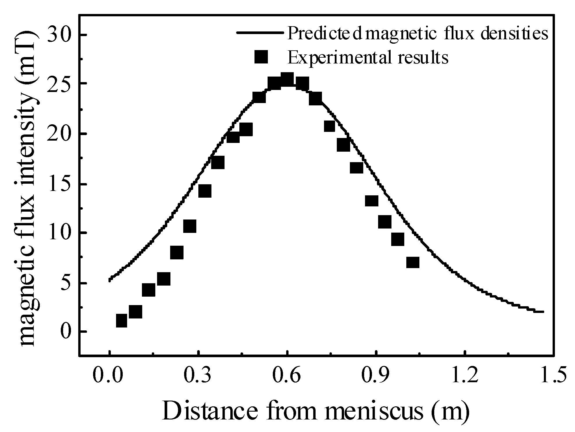
- EMS model
- (3)
- Solidification model
3.2. Effect of Nozzle Structure on the Steel Flow and Heat Transfer
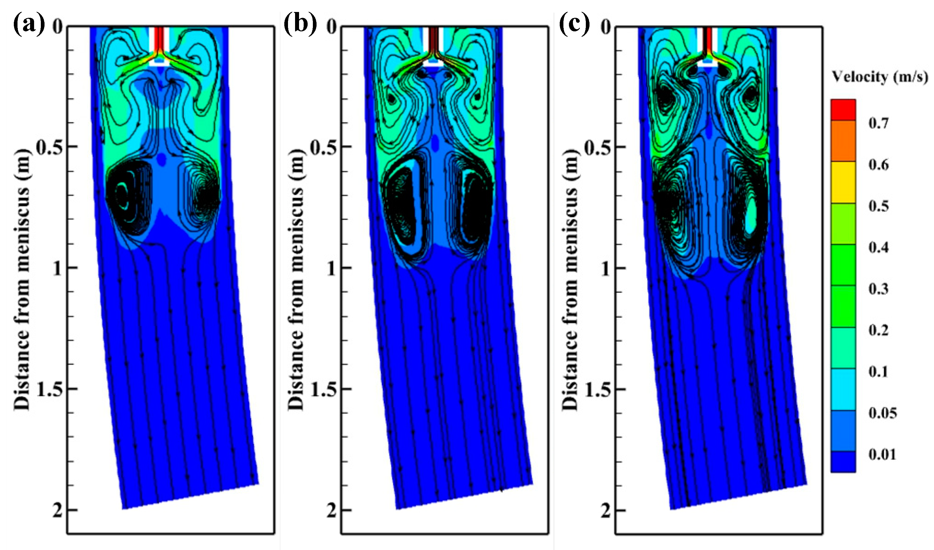
3.2.1. Effect of Nozzle Structure on the Steel Fluid Flow
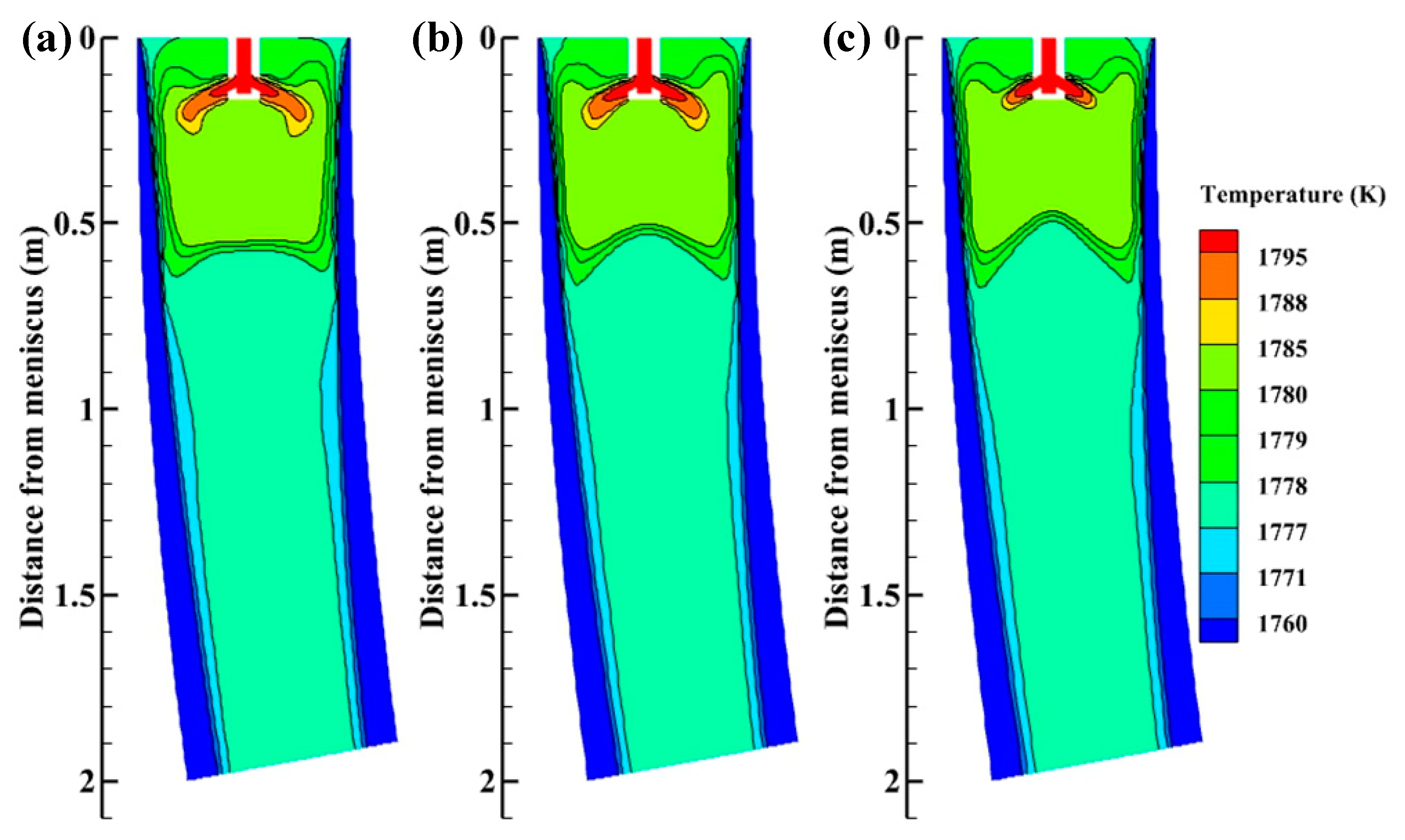
3.2.2. Effect of Nozzle Structure on Heat Transfer and Solidification
3.3. Effect of M-EMS on the Steel Flow and Heat Transfer
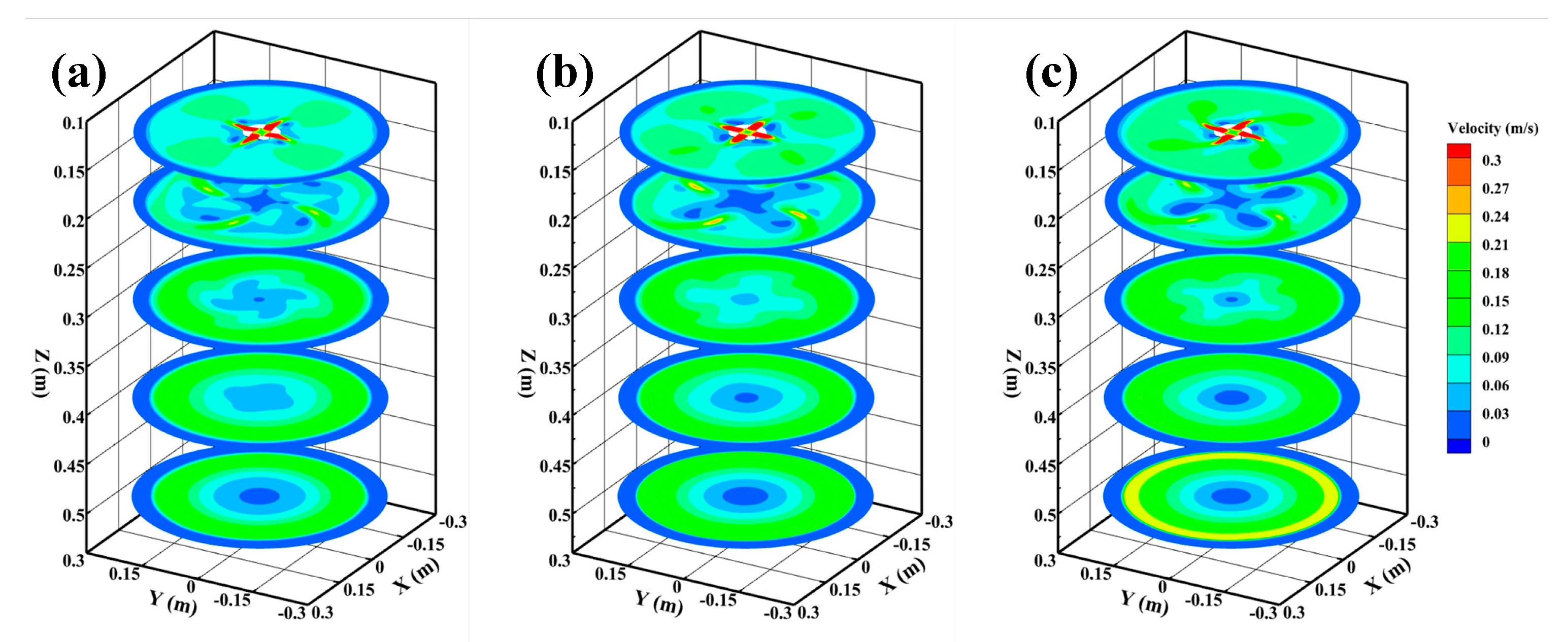
3.3.1. Effect of M-EMS on the Steel Fluid Flow
3.3.2. Effect of M-EMS on Heat Transfer and Solidification
3.4. Effect of Nozzle Structure on Level Fluctuation
4. Conclusions
- (1)
- Compared with the original SEN, SFN forms the third small recirculating zone near the meniscus, which can promote the flow of molten steel to the meniscus and increase the steel temperature at the meniscus. SFN can shift the isotherm upward, improve the mold cooling efficiency and realize low-temperature casting.
- (2)
- The horizontal swirl produced by SFN reduces the washing of the high-temperature molten steel on the initial shell and eliminates the uneven growth of the solidified shell caused by mold curvature.
- (3)
- The effect of M-EMS is similar to that of SFN. With the application of M-EMS, the high-temperature zone in the mold’s upper part enlarges, which promotes the steel superheat dissipation and is beneficial to the stable growth of the solidified shell.
- (4)
- When the M-EMS direction is opposite to the SFN direction, the tangential velocity and the level fluctuation of the meniscus can be reduced. When the M-EMS direction is the same as the SFN direction, the level fluctuation increases, which easily produces slag entrapment.
Author Contributions
Funding
Institutional Review Board Statement
Informed Consent Statement
Data Availability Statement
Conflicts of Interest
References
- Aboutalebi, M.M.; Lapointe, F.; D’amours, J.; Isac, M.; Guthrie, R.I. Numerical modelling of fluid flows in square billet moulds, using a new nozzle orientation in the presence of an in-mould rotary electromagnetic stirrer. Ironmak. Steelmak. 2018, 46, 819–826. [Google Scholar] [CrossRef]
- Aboutalebi, M.M.; Lapointe, F.; D’amours, J.; Isac, M.; Guthrie, R.I. Effects of angle of rotation of submerged entry nozzle on fluid flows in a square billet casting mold. JOM 2018, 70, 2088–2095. [Google Scholar] [CrossRef] [Green Version]
- Xie, Q.; Nabeel, M.; Ersson, M.; Ni, P. A review on swirling flow casting technology in steel production. Steel Res. Int. 2022, 93, 2100410. [Google Scholar] [CrossRef]
- Yokoya, S.; Asako, Y.; Hara, S.; Szekely, J. Control of immersion nozzle outlet flow pattern through the use of swirling flow in continuous casting. ISIJ Int. 1994, 34, 883–888. [Google Scholar] [CrossRef] [Green Version]
- Yokoya, S.; Takagi, S.; Iguchi, M.; Asako, Y.; Westoff, R.; Hara, S. Swirling effect in immersion nozzle on flow and heat transport in billet continuous casting mold. ISIJ Int. 1998, 38, 827–833. [Google Scholar] [CrossRef] [Green Version]
- Yokoya, S.; Takagi, S.; Iguchi, M.; Marukawa, K.; Hara, S. Swirling flow effect in immersion nozzle on flow in slab continuous casting mold. ISIJ Int. 2000, 40, 578–583. [Google Scholar] [CrossRef] [Green Version]
- Tsukaguchi, Y.; Hayashi, H.; Kurimoto, H.; Yoyoka, S.; Marukawa, K.; Tanaka, T. Development of swirling-flow submerged entry nozzles for slab casting. ISIJ Int. 2010, 50, 721–729. [Google Scholar] [CrossRef] [Green Version]
- Li, D.; Su, Z.; Chen, J.; Wang, Q.; Marukawa, K.; He, J. Numerical simulation of swirling flow in divergent submerged entry nozzle in round billet continuous casting of steel. Acta Metall. Sin. 2013, 49, 871–880. [Google Scholar] [CrossRef]
- Li, D.; Su, Z.; Chen, J.; Wang, Q.; Yang, Y.; Nakajima, K.; Marukawa, K.; He, J. Effects of electromagnetic swirling flow in submerged entry nozzle on square billet continuous casting of steel process. ISIJ Int. 2013, 53, 1187–1194. [Google Scholar] [CrossRef] [Green Version]
- Wu, C.; Wang, Q.; Li, D.; Zhu, X.; Jin, B.; Wang, L.; Lei, H. Macrosegregation under new flow pattern and temperature distribution induced by electromagnetic swirling flow in nozzle during continuous casting of square billet. J. Mater. Res. Technol. 2020, 9, 5630–5639. [Google Scholar] [CrossRef]
- Wu, C.; Li, D.; Zhu, X.; Wang, Q.; Oleksandr, T.; Lei, H. Influence of electromagnetic swirling flow in nozzle on solidification structure and macrosegregation of continuous casting square billet. Acta Metall. Sin. 2019, 55, 875–884. [Google Scholar]
- Ni, P.; Ersson, M.; Jonsson, L.T.; Zhang, T.; Jönsson, P.G. Effect of immersion depth of a swirling flow tundish SEN on multiphase flow and heat transfer in mold. Metals 2018, 8, 910. [Google Scholar] [CrossRef] [Green Version]
- Xie, Q.; Ni, P.; Ersson, M.; Jönsson, P.G.; Li, Y. Numerical simulations on dynamic behavior of multiphase flow and heat transfer in a round mold with a swirling flow tundish design. Metall. Mater. Trans. B 2022, 53, 3197–3214. [Google Scholar] [CrossRef]
- Bai, H.; Ni, P.; Ersson, M.; Zhang, T.; Jönsson, P.G. Effect of swirling flow tundish submerged entry nozzle outlet design on multiphase flow and heat transfer in mould. Ironmak. Steelmak. 2019, 46, 911–920. [Google Scholar] [CrossRef] [Green Version]
- Sun, H.; Zhang, J. Macrosegregation improvement by swirling flow nozzle for bloom continuous castings. J. Mater. Res. Technol. 2014, 45, 936–946. [Google Scholar] [CrossRef]
- Lin, P.; Jin, Y.; Yang, F.; Liu, Z.; Jing, R.; Cao, Y.; Xiang, Y.; Cheng, C.; Li, Y. A Simulation and Optimization Study of the Swirling Nozzle for Eccentric Flow Fields of Round Molds. Metals 2020, 10, 691. [Google Scholar] [CrossRef]
- Sun, H.; Li, L. Application of swirling flow nozzle and investigation of superheat dissipation casting for bloom continuous casing. Ironmak. Steelmak. 2016, 43, 228–233. [Google Scholar] [CrossRef]
- Flemings, M.C. Behavior of metal alloys in the semisolid state. Metall. Trans. A 1991, 22, 957–981. [Google Scholar] [CrossRef]
- Wang, B.; Yang, Z.; Zhang, X.; Wang, Y.; Nie, C.; Liu, Q.; Dong, H. Analysis of the effects of electromagnetic stirring on solidification structure of bearing steel. Metalurgija 2015, 54, 327–330. [Google Scholar]
- Spitzer, K.H.; Dubke, M.; Schwerdtfeger, K. Rotational electromagnetic stirring in continuous casting of round strands. Metall. Trans. B 1986, 17, 119–131. [Google Scholar] [CrossRef]
- Steinbach, S.; Ratke, L. The effect of rotating magnetic fields on the microstructure of directionally solidified Al–Si–Mg alloys. Mst. Sci. Eng. A 2005, 413, 200–204. [Google Scholar] [CrossRef]
- Li, Y.; Sun, Y.; Bai, X. Numerical simulation of flow, heat, solidification, solute transfer and electromagnetic field for vertical mold and curved mold of billet. ISIJ Int. 2021, 61, 802–813. [Google Scholar] [CrossRef]
- Li, X.; Zhang, Z.; Lv, M.; Fang, M.; Liu, K. Numerical simulation of the fluid flow, heat transfer, and solidification in ultrahigh speed continuous casting billet mold. Steel Res. Int. 2022, 93, 2100673. [Google Scholar] [CrossRef]
- Jauregui, R.; Silva, F. Numerical validation methods. Numer. Anal. -Theory Appl. 2011, 8, 155–174. [Google Scholar]
- Ren, B.; Chen, D.; Wang, H.; Long, M. Numerical analysis of coupled turbulent flow and macroscopic solidification in a round bloom continuous casting mold with electromagnetic stirring. Steel Res. Int. 2015, 86, 1104–1115. [Google Scholar] [CrossRef]
- Wang, Q.; Zhang, L. Influence of FC-mold on the full solidification of continuous casting slab. JOM 2016, 68, 2170–2179. [Google Scholar] [CrossRef]
- Yang, B.; Li, J.; Zhang, L.; Zhang, Y.; Cui, Y.; Xu, C. Simulation analysis on flow field and temperature field in mould of special thick slab caster. Teh. Vjesn. 2019, 26, 566–570. [Google Scholar]
- Aboutalebi, M.R.; Hasan, M.; Guthrie, R.I.L. Coupled turbulent flow, heat, and solute transport in continuous casting processes. Metall. Mater. Trans. B 1995, 26, 731–744. [Google Scholar] [CrossRef]
- Dong, Q.; Zhang, J.; Yin, Y.; Wang, B. Three-dimensional numerical modeling of macrosegregation in continuously cast billets. Metals 2017, 7, 209. [Google Scholar] [CrossRef] [Green Version]
- Yin, Y.; Zhang, J.; Dong, Q.; Li, Y. Modelling on inclusion motion and entrapment during the full solidification in curved billet caster. Metals 2018, 8, 320. [Google Scholar] [CrossRef] [Green Version]
- Li, D.; Wu, H.; Wang, H.; Li, H. Growth of solidified shell in bloom continuous casting mold of hypo-peritectic steel based on a FeS tracer method. J. Iron Steel Res. Int. 2020, 27, 782–787. [Google Scholar] [CrossRef]
- Jiang, D.; Zhu, M. Solidification structure and macrosegregation of billet continuous casting process with dual electromagnetic stirrings in mold and final stage of solidification: A numerical study. Metall. Mater. Trans. B 2016, 47, 3446–3458. [Google Scholar] [CrossRef]
- Yin, S.; Luo, S.; Zhang, W.; Wang, W.; Zhu, M. Numerical simulation of macrosegregation in continuously cast gear steel 20CrMnTi with final electromagnetic stirring. J. Iron Steel Res. Int. 2020, 28, 424–436. [Google Scholar] [CrossRef]
- Ren, B.; Chen, D.; Wang, H.; Long, M.; Han, Z. Numerical simulation of fluid flow and solidification in bloom continuous casting mould with electromagnetic stirring. Ironmak. Steelmak. 2014, 42, 401–408. [Google Scholar] [CrossRef]
- Yang, Z.; Wang, B.; Zhang, X.; Wang, Y.; Dong, H.; Liu, Q. Effect of electromagnetic stirring on molten steel flow and solidification in bloom mold. J. Iron Steel Res. Int. 2014, 21, 1095–1103. [Google Scholar] [CrossRef]
- Zhang, W.; Luo, S.; Chen, Y.; Wang, W.; Zhu, M. Numerical simulation of fluid flow, heat transfer, species transfer, and solidification in billet continuous casting mold with M-EMS. Metals 2019, 9, 66. [Google Scholar] [CrossRef] [Green Version]
- Yuan, Q.; Thomas, B.G.; Vanka, S.P. Study of transient flow and particle transport in continuous steel caster molds: Part I. Fluid flow. Metall. Mater. Trans. B. 2004, 35, 685–702. [Google Scholar] [CrossRef] [Green Version]
- Liu, H.; Xu, M.; Qiu, S.; Zhang, H. Numerical simulation of fluid flow in a round bloom mold with in-mold rotary electromagnetic stirring. Metall. Mater. Trans. B. 2012, 43, 1657–1675. [Google Scholar] [CrossRef]


| Parameters | SEN | SFN |
|---|---|---|
| Inner diameter (mm) | 45 | 45 |
| External diameter (mm) | 90 | 90 |
| Port height (mm) | 35 | 35 |
| Port width (mm) | 25 | 25 |
| Port angle (°) | 0 | ±15 |
| Immersion depth (mm) | 100 | 100 |
| C | Si | Mn | Cr | Mo | P | S | Fe |
|---|---|---|---|---|---|---|---|
| 0.12 | 0.3 | 0.38 | 8.19 | 0.37 | 0.01 | 0.007 | Bal. |
| Parameters | Values |
|---|---|
| Round bloom dimension (mm) | Φ600 |
| Casting machine radius (mm) | 14,000 |
| Mold length (mm) | 700 |
| Casting speed (m/min) | 0.24 |
| Current intensity of M-EMS (A) | 300 |
| Current frequency of M-EMS (Hz) | 2 |
| Viscosity (Pa·s) | 0.0053 |
| Density (kg/m3) | 7000 |
| Liquidus temperature (K) | 1778 |
| Solidus temperature (K) | 1683 |
| Specific heat (J/kg·K) | 750 |
| Latent heat of fusion (J/kg) | 250,000 |
Publisher’s Note: MDPI stays neutral with regard to jurisdictional claims in published maps and institutional affiliations. |
© 2022 by the authors. Licensee MDPI, Basel, Switzerland. This article is an open access article distributed under the terms and conditions of the Creative Commons Attribution (CC BY) license (https://creativecommons.org/licenses/by/4.0/).
Share and Cite
Wang, J.; Zhu, J.; Yang, Y.; Wang, W.; Qiu, G.; Li, X. Effect of Swirling Flow Nozzle on Fluid Flow and Solidification in a Round Bloom Continuous Casting Mold. Materials 2022, 15, 8474. https://doi.org/10.3390/ma15238474
Wang J, Zhu J, Yang Y, Wang W, Qiu G, Li X. Effect of Swirling Flow Nozzle on Fluid Flow and Solidification in a Round Bloom Continuous Casting Mold. Materials. 2022; 15(23):8474. https://doi.org/10.3390/ma15238474
Chicago/Turabian StyleWang, Jianli, Jiayu Zhu, Yongkun Yang, Weian Wang, Guoxing Qiu, and Xiaoming Li. 2022. "Effect of Swirling Flow Nozzle on Fluid Flow and Solidification in a Round Bloom Continuous Casting Mold" Materials 15, no. 23: 8474. https://doi.org/10.3390/ma15238474