
Study on the Influence of Delamination Damage on the Processing Quality of Composite Laminates

Abstract
:1. Introduction
2. Experiment
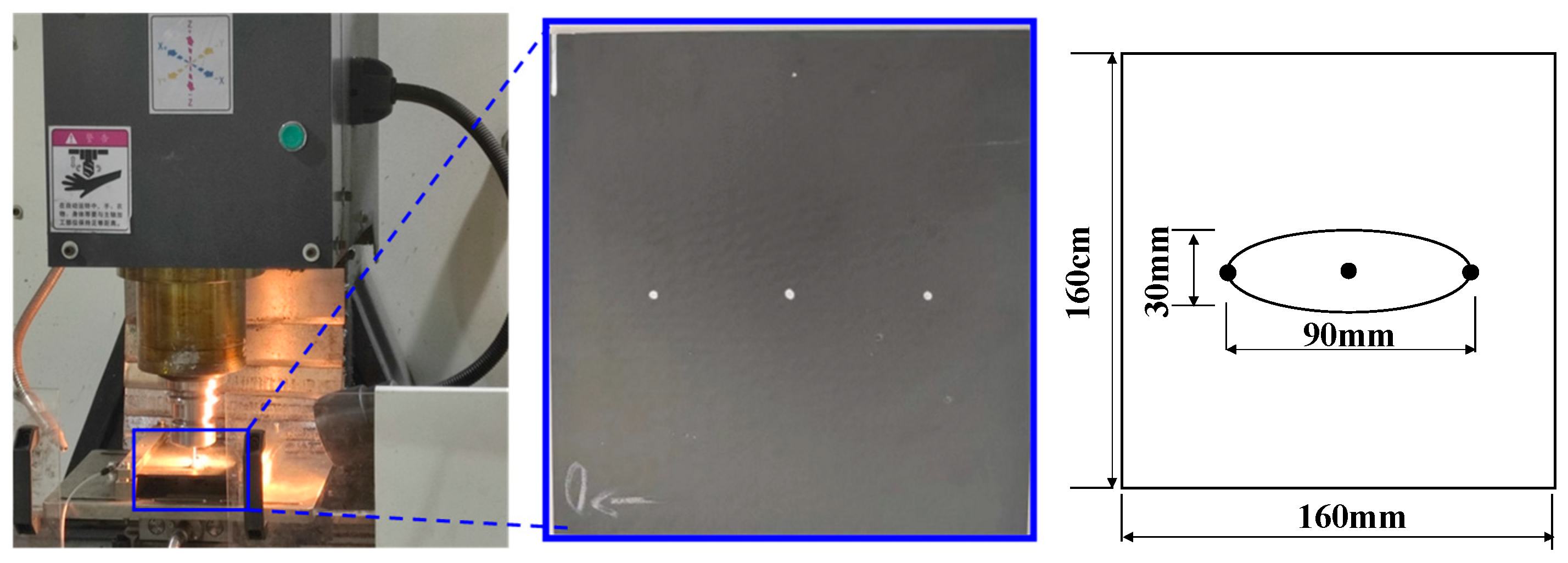
2.1. Sample
2.2. Drilling Test
2.3. Finite Element Simulation Model
3. Results and Analysis
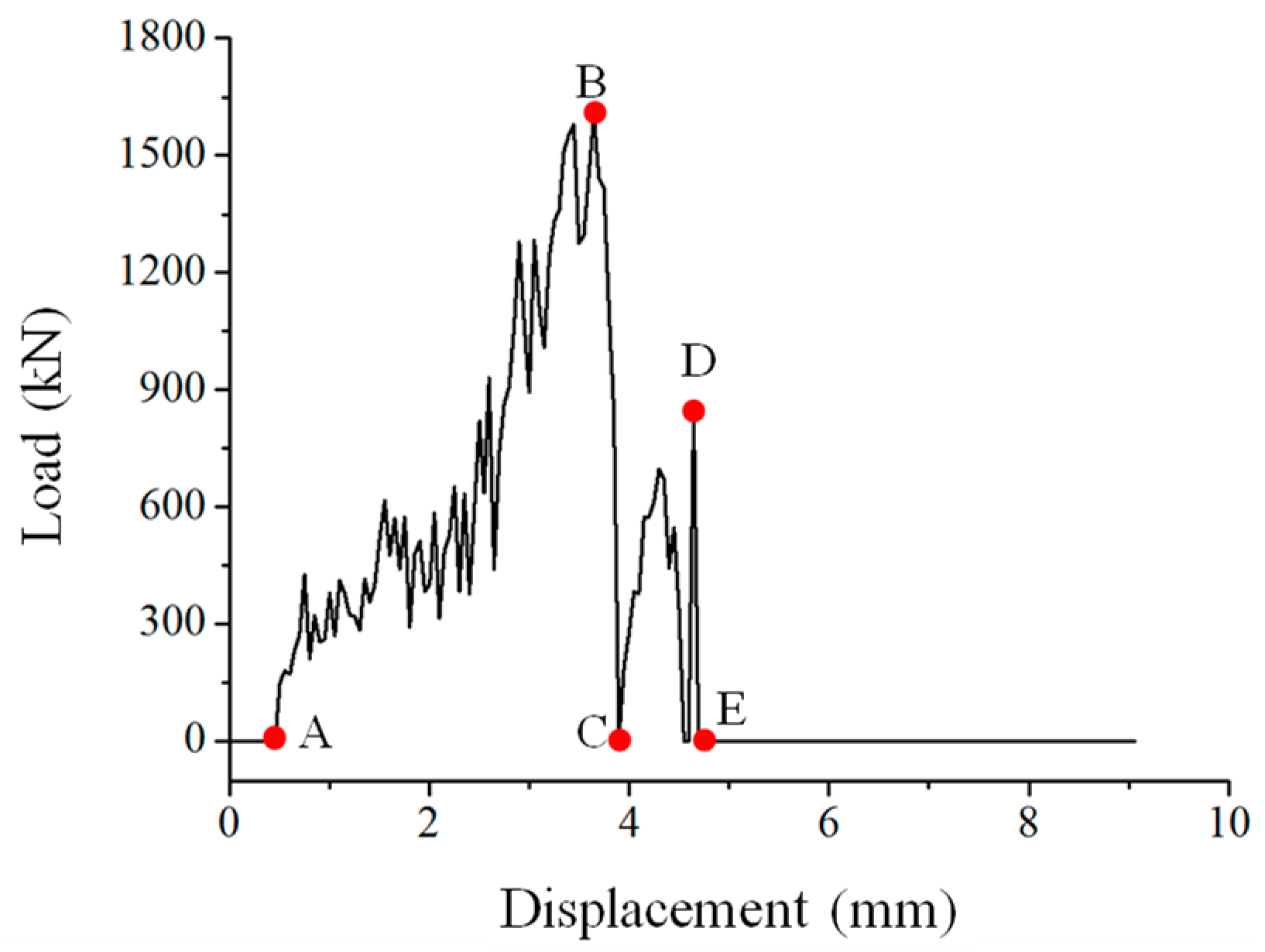
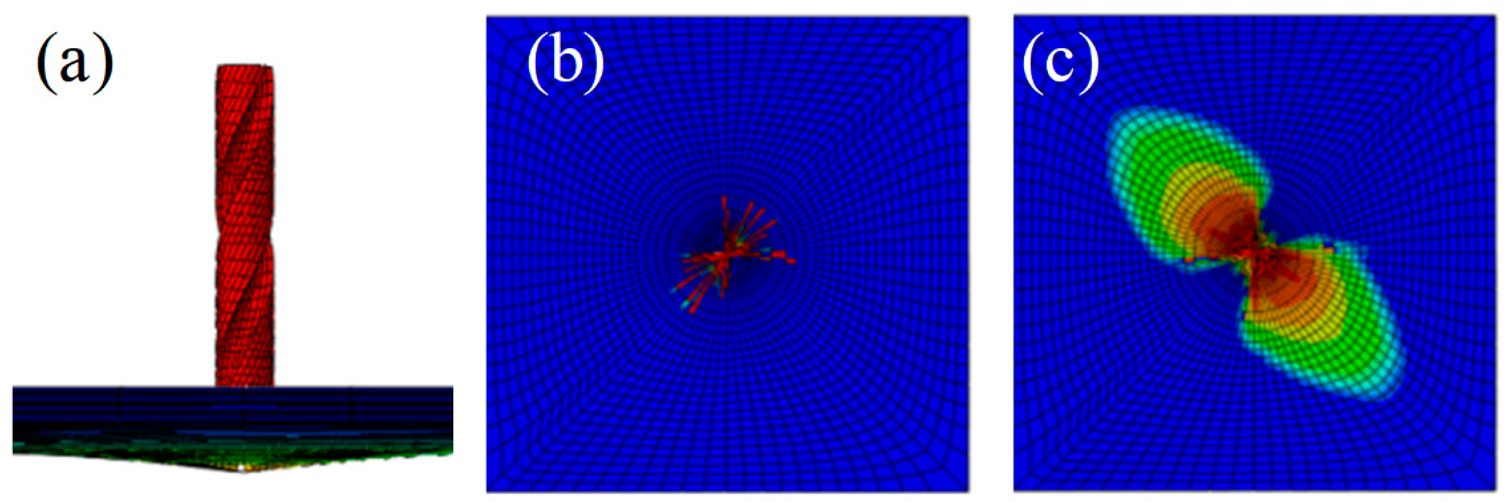
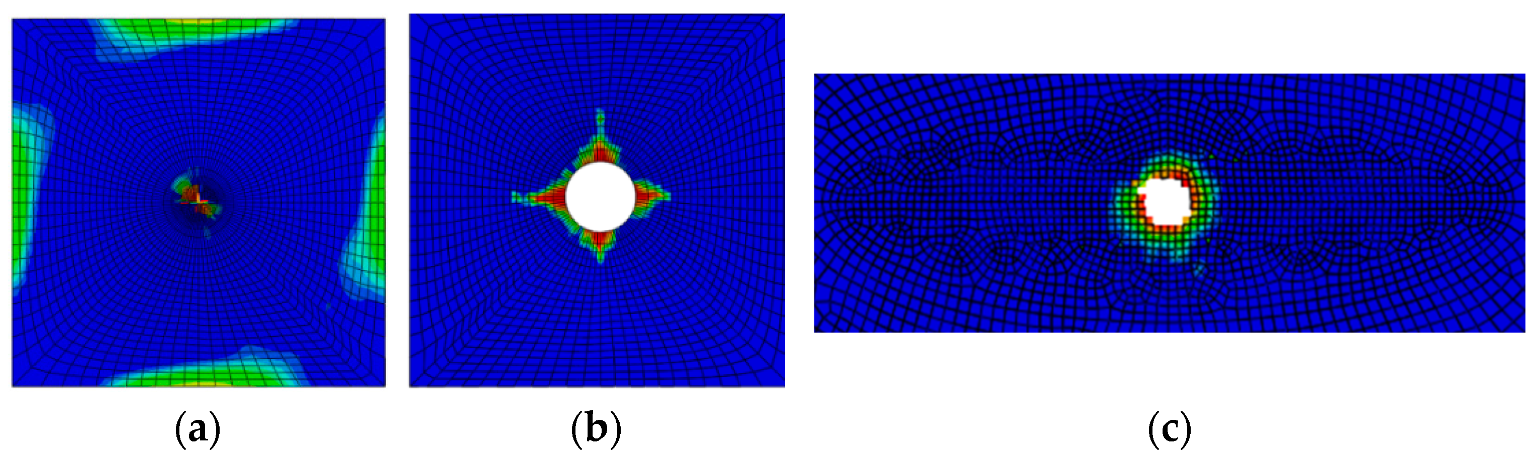
3.1. Analysis of the Drilling Damage Propagation Mechanism
3.2. Analysis of Machining Axial Force
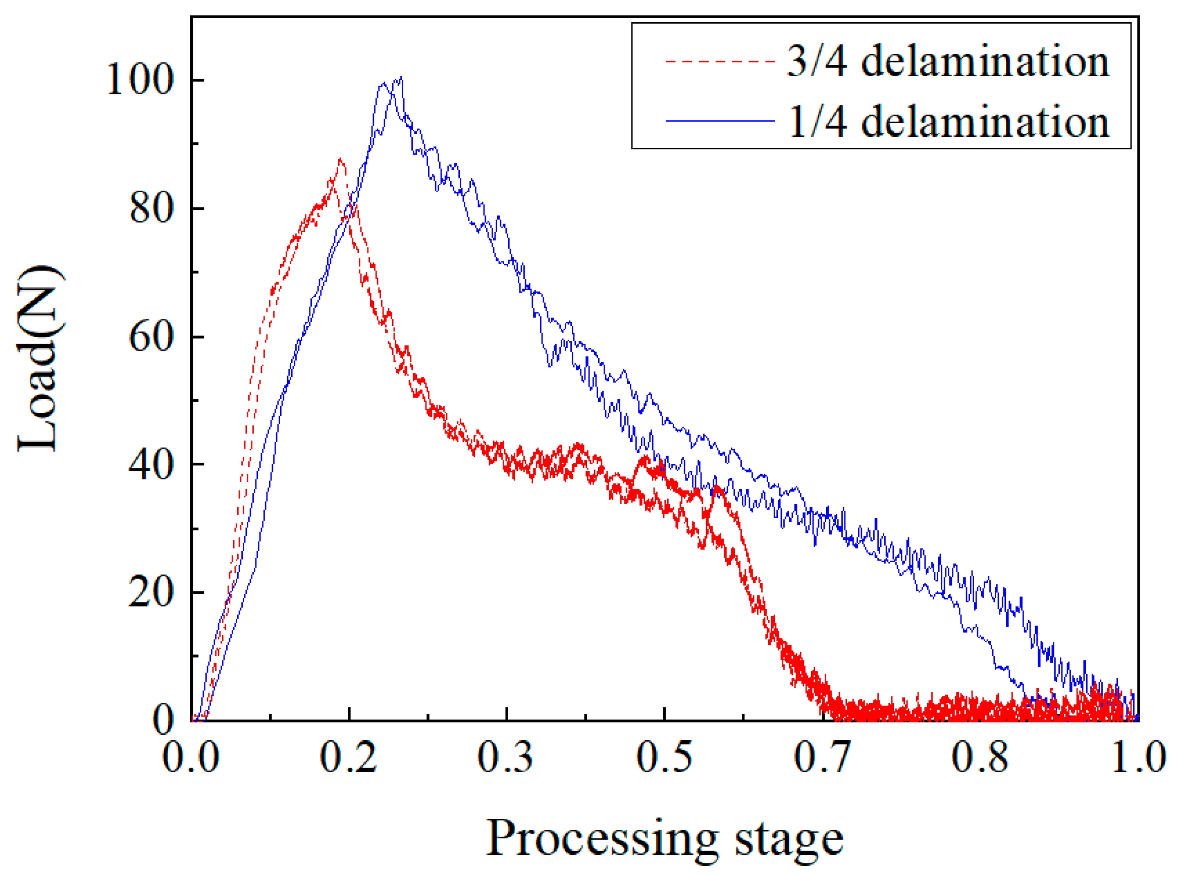
3.2.1. Effect of Layer Thickness
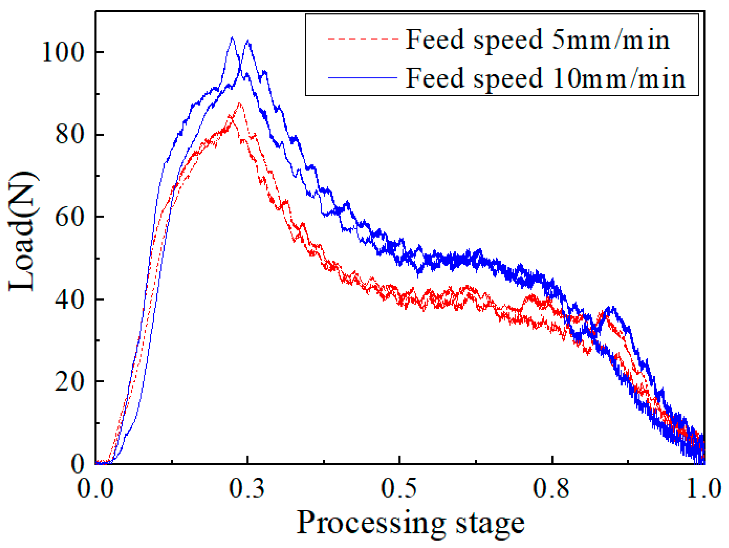
3.2.2. Effect of Feed Speed
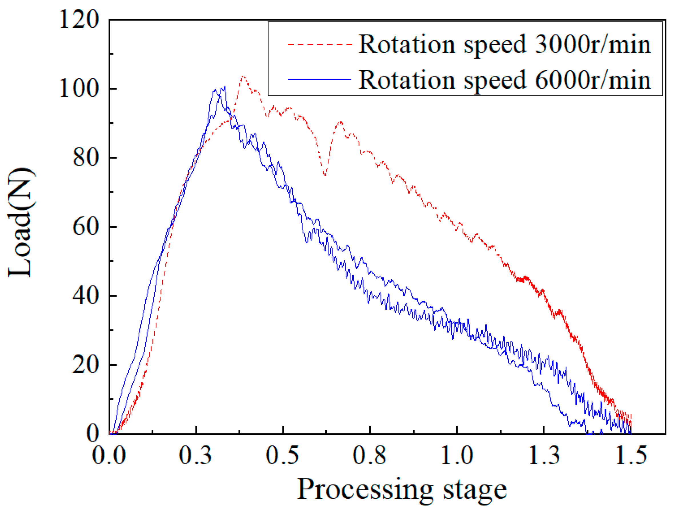
3.2.3. Effect of Rotation Speed
4. Conclusions
- (1)
- Based on finite element simulation software, a dynamic machining simulation model of composite laminates with delamination was established. Through analysis of the change in axial force of the drill bit, the damage to the laminates, and the expansion of the original delamination, it was revealed that the damage to composite laminates during the drilling process mainly included three stages: feed compression damage, rebound damage expansion, and secondary feed inner wall delamination expansion.
- (2)
- With the help of vertical CNC machine tools and precision force measuring instruments, a constant parameter drilling test design was carried out for the laminated composite plate samples containing layers, and the effects of different processing parameters on the processing axial force were qualitatively compared. The results showed that the effect of rotational speed on the cutting force for the composite laminates was similar to that of intact composite laminates, and the two were positively correlated. The feed speed and layering position had the greatest influence on the axial force of machining. The faster the feed speed, the greater the axial force of machining. With the increase of layering thickness, the axial force of machining decreased. Similar results were shown in in a drilling experiment of intact composite laminates. The drilling feed speed had a great influence on the drilling axial force. When the drilling feed speed was higher, the drilling axial force is larger; the delamination factor also increased, and the delamination defect was aggravated [36].
Author Contributions
Funding
Institutional Review Board Statement
Informed Consent Statement
Conflicts of Interest
References
- Yao, W.; Dong, F.; Hai, F. Effect of single bolt repair on compression bearing capacity of impact damaged carbon fiber/epoxy composite laminates. J. Compos. Mater. 2020, 37, 2833–2843. [Google Scholar]
- Saleem, R.; Toubal, L.; Zitoune, R. Investigating the effect of machining processes on the mechanical behavior of composite plates with circular holes. Compos. Part A Appl. Sci. Manuf. 2013, 55, 169–177. [Google Scholar] [CrossRef]
- Karimi, N.R.; Heidary, H.; Ahmadi, M. Residual tensile strength monitoring of drilled composite materials by acoustic emission. Mater. Des. 2012, 40, 229–236. [Google Scholar] [CrossRef]
- Senthil, K.M.; Prabukarth, A.; Krishnaraj, V. Study on tool wear and chip formation during drilling carbon fiber reinforced polymer(CFRP)/titanium alloy(Ti6Al4V) stacks. Procedia Eng. 2013, 64, 582–592. [Google Scholar] [CrossRef] [Green Version]
- Hou, G.; Qiu, J.; Zhang, K. Comparative tool wear and hole quality investigation in drilling of aerospace grade T800 CFRP using different external cooling lubricants. Int. J. Adv. Manuf. Technol. 2020, 106, 937–951. [Google Scholar] [CrossRef]
- Bi, S.; Liang, J. Experimental studies and optimization of process parameters for burrs in dry drilling of stacked metal materials. Int. J. Adv. Manuf. Technol. 2011, 53, 867–876. [Google Scholar] [CrossRef]
- Eneyew, E.D.; Ramulu, M. Experimental study of surface quality and damage when drilling unidirectional CFRP composites. J. Mater. Res. Technol. 2014, 3, 354–362. [Google Scholar] [CrossRef] [Green Version]
- Denkena, B.; Boehnk, D.; Dege, J.H. Helical milling of CFRP-titanium layer compounds. J. Manuf. Sci. Technol. 2014, 1, 64–69. [Google Scholar] [CrossRef]
- Li, Z.; Hong, M.; Wang, M. Machining accuracies for step multi-element varying-parameter vibration drilling onlaminated composite materials. J. Shanghai Jiao Tong Univ. 2002, 36, 1100–1103. [Google Scholar] [CrossRef]
- Neugebauer, R.; Ben, H.U.; Ihlenfeldt, S. Acoustic emission as a tool for identifying drill position in fiber rein forced plastic and aluminum stacks. Int. J. Mach. Tools Manuf. 2012, 57, 20–26. [Google Scholar] [CrossRef]
- Yan, C.; Ende, G.; Yucan, F.; Honghua, S.; Jiuhua, X. Research status and prospect of pore making technology for carbon fiber reinforced resin matrix composites. J. Compos. Mater. 2015, 32, 301–316. [Google Scholar]
- Singh, A.P.; Sharma, M. Modelling of thrust force during drilling of fiber reinforced plastic composites. Procedia Eng. 2013, 51, 630–636. [Google Scholar] [CrossRef]
- Liu, J.; Chen, G. An investigation of workpiece temperature variation of helical milling for carbon fiber rein-forced plastics (CFRP). Int. J. Mach. Tools Manuf. 2014, 86, 89–103. [Google Scholar] [CrossRef]
- Sharma, V.; Meena, M.L.; Kumar, M. Mechanical Properties of Unfilled and Particulate Filled Glass Fiber Reinforced Polymer Composites-A Review. In AIP Conference Proceedings; AIP Publishing LLC: Melville, NY, USA, 2019; p. 020037. [Google Scholar]
- Ding, V.; Fu, Y.; Su, H. Experimental studies on drilling tool load and machining quality of C/SiC composites in rotary ultrasonic machining. J. Mater. Process. Technol. 2014, 214, 2900–2907. [Google Scholar] [CrossRef]
- Singh, J.; Kumar, M.; Kumar, S. Properties of Glass-Fiber Hybrid Composites: A Review. Polym. Plast. Technol. Eng. 2016, 56, 455–469. [Google Scholar] [CrossRef]
- Chen, W.C. Some experimental investigations in the drilling of carbon fiber-reinforced plastic (CFRP) composite laminates. Int. J. Mach. Tools Manuf. 1997, 37, 1097–1108. [Google Scholar] [CrossRef]
- Bajpai, P.C.; Debnath, K.; Singh, I. Hole making in natural fiber-reinforced polylactic acid laminates: An experimental investigation. J. Thermoplast. Compos. Mater. 2017, 30, 30–46. [Google Scholar] [CrossRef]
- Davim, J.; Paulo, J.; Campos, R. A novel approach based on digital image analysis to evaluate the delamination factor after drilling composite laminates. Compos. Sci. Technol. 2007, 67, 1939–1945. [Google Scholar] [CrossRef]
- Su, Y. Effect of the cutting speed on the cutting mechanism in machining CFRP. Compos. Struct. 2019, 220, 662–676. [Google Scholar] [CrossRef]
- Su, Y.; Jia, Z.; Niu, B. Size effect of depth of cut on chip formation mechanism in machining of CFRP. Compos. Struct. 2017, 164, 316–327. [Google Scholar] [CrossRef]
- Miah, F.; Deluycke, E.; Lachaud, F. Effect of Different Cutting Depths to the Cutting Forces and Machining Quality of CFRP Parts in Orthogonal Cutting: A Numerical and Experimental Comparison. Int. Mech. Eng. Congr. Expo. 2018, 52002, V001T03A008. [Google Scholar]
- Hou, G.; Luo, B.; Zhang, K. Investigation of high temperature effect on CFRP cutting mechanism based on a temperature controlled orthogonal cutting experiment. Compos. Struct. 2021, 268, 113967. [Google Scholar] [CrossRef]
- Meng, Q.; Cai, J.; Cheng, H. Investigation of CFRP cutting mechanism variation and the induced effects on cutting response and damage distribution. Int. J. Adv. Manuf. Technol. 2020, 106, 2893–2907. [Google Scholar] [CrossRef]
- Ran, Y.K.; Donaldson, S.L. Experimental and analytical studies on the damage initiation in composite laminates at cryogenic temperatures. Compos. Struct. 2006, 76, 62–66. [Google Scholar] [CrossRef]
- Nilsson, K.F.; Asp, L.E.; Alpman, J.E. Delamination buckling and growth for delaminations at different depths in a slender composite panel. Int. J. Solids Struct. 2001, 38, 3039–3071. [Google Scholar] [CrossRef]
- Vlach, J.; Doubrava, R.; Růžek, R.; Raška, J.; Horňas, J.; Kadlec, M. Strain-Field Modifications in the Surroundings of Impact Damage of Carbon/Epoxy Laminate. Polymers 2022, 14, 3243. [Google Scholar] [CrossRef]
- Vlach, J.; Doubrava, R.; Růžek, R.; Raška, J.; Horňas, J.; Kadlec, M. Linearization of Composite Material Damage Model Results and Its Impact on the Subsequent Stress–Strain Analysis. Polymers 2022, 14, 1123. [Google Scholar] [CrossRef]
- Samal, S. Interface failure and delamination resistance of fiber-reinforced geopolymer composite by simulation and experimental method. Cem. Concr. Compos. 2022, 128, 104420. [Google Scholar] [CrossRef]
- Fotouhi, M.F.; Pashmforoush, A.M. Monitoring the initiation and growth of delamination in composite materials using acoustic emission under quasi-static three-point bending test. J. Reinf. Plast. Compos. 2011, 30, 1481–1493. [Google Scholar] [CrossRef]
- Fawaz, S.A. Application of the virtual crack closure technique to calculate stress intensity factors for through cracks with an elliptical crack front. Eng. Fract. Mech. 1998, 59, 327–342. [Google Scholar] [CrossRef]
- Xie, D.; Biggers, S., Jr. Progressive crack growth analysis using interface element based on the virtual crack closure technique. Finite Elem. Anal. Des. 2006, 42, 977–984. [Google Scholar] [CrossRef]
- Miroslav, M. A finite element model for propagating delamination in laminated composite plates based on the Virtual Crack Closure method. Compos. Struct. 2016, 150, 8–19. [Google Scholar] [CrossRef]
- Short, G.J.; Guild, F.J.; Pavier, M.J. Delaminations in flat and curved composite laminates subjected to compressive load. Compos. Struct. 2002, 58, 249–258. [Google Scholar] [CrossRef]
- Xu, X.; Man, H. Strength prediction of composite laminates with multiple elliptical holes. Int. J. Solids Struct. 2000, 37, 2887–2900. [Google Scholar] [CrossRef]
- Ma, G.R. Study on the Propagation Rule of CFRP Forming Delamination Defect in the Drilling Cross Edge Extrusion Stage; Dalian University of Technology: Dalian, China, 2018; Volume 06, p. 50. [Google Scholar]


| E1 (GPa) | E2 (GPa) | G12 (GPa) | G13 (GPa) | XT (MPa) |
| 140 | 9 | 5 | 5 | 1400 |
| YC (MPa) | YT (MPa) | XC (MPa) | S12 (MPa) | S23 (MPa) |
| 50 | 50 | 180 | 99 | 99 |
| Serial | Rotation Speed (r/min) | Feed Speed (mm/min) |
|---|---|---|
| 1 | 3000 | 5 |
| 2 | 3000 | 10 |
| 3 | 6000 | 5 |
| 4 | 6000 | 10 |
Publisher’s Note: MDPI stays neutral with regard to jurisdictional claims in published maps and institutional affiliations. |
© 2022 by the authors. Licensee MDPI, Basel, Switzerland. This article is an open access article distributed under the terms and conditions of the Creative Commons Attribution (CC BY) license (https://creativecommons.org/licenses/by/4.0/).
Share and Cite
Yu, J.; Shan, Y.; Zhao, Y.; Mo, R. Study on the Influence of Delamination Damage on the Processing Quality of Composite Laminates. Materials 2022, 15, 8572. https://doi.org/10.3390/ma15238572
Yu J, Shan Y, Zhao Y, Mo R. Study on the Influence of Delamination Damage on the Processing Quality of Composite Laminates. Materials. 2022; 15(23):8572. https://doi.org/10.3390/ma15238572
Chicago/Turabian StyleYu, Jiali, Yimeng Shan, Yiming Zhao, and Ran Mo. 2022. "Study on the Influence of Delamination Damage on the Processing Quality of Composite Laminates" Materials 15, no. 23: 8572. https://doi.org/10.3390/ma15238572