Article

Formation and Inhibition Mechanism of Na8SnSi6O18 during the Soda Roasting Process for Preparing Na2SnO3

School of Minerals Processing and Bioengineering, Central South University, Changsha 410083, China
*
Authors to whom correspondence should be addressed.
Materials 2022, 15(24), 8718; https://doi.org/10.3390/ma15248718
Submission received: 8 October 2022 / Revised: 22 November 2022 / Accepted: 3 December 2022 / Published: 7 December 2022
(This article belongs to the Special Issue Advances in Processing and Characterization of Mineral Materials)

Abstract

:
To produce Na2SnO3, which is widely used in the ceramics and electroplating industries, a novel process for the preparation of sodium stannate from cassiterite concentrates was developed successfully by the authors’ group. It was found that sodium stannosilicate (Na8SnSi6O18) was easily formed due to the main gangue of quartz in cassiterite concentrates, which was almost insoluble and decreased the quality of Na2SnO3. The formation and transitions of Na8SnSi6O18 in the SnO2–SiO2–Na2CO3 system roasted under a CO–CO2 atmosphere were determined. The results indicated that the formation of Na8SnSi6O18 could be divided into two steps: SnO2 reacted with Na2CO3 to form Na2SnO3, and then Na2SnO3 was rapidly combined with SiO2 and Na2CO3 to form low melting point Na8SnSi6O18. In addition, Na8SnSi6O18 can be decomposed into Na2SiO3 and Na2SnO3 by using excess Na2CO3.

1. Introduction

Na2SnO3 is an important raw material to produce stannate ceramics and electroplating materials [1,2,3,4,5]. A novel soda roasting–leaching process has been developed by the authors’ group using cassiterite concentrates as raw materials, by which Na2SnO3 was prepared efficiently and cleanly [6]. Previous studies have showed that the solid-state reactions between SnO2 and Na2CO3 are accelerated under a CO–CO2 atmosphere [7,8,9,10]. Then, a trihydrate sodium stannate product with high purity was obtained, which meets the requirements of an industrial first-grade product [6]. In addition, the soda roasting process has also been applied for the comprehensive utilization of tin-bearing secondary waste [11,12,13,14].
Cassiterite (SnO2) is the primary source of tin. It is naturally formed by magmatic-hydrothermal processes and occurs in granite pegmatites, quartz veins, greisens associated with granites, highly fractionated granites, as well as placer deposits [15,16,17,18]. Nevertheless, gangue minerals, including calcite, magnetite and other oxides, cannot be perfectly separated by beneficiation combined methods. Hence, oxidizing roasting and hydrochloric acid leaching processes are applied to remove impurity elements (Fe, Ca, Mg, S, As, Pb, Zn, etc.). However, quartz is stubborn and difficult to remove during the pretreatment process, resulting in the residue of SiO2 in tin concentrates being as high as 8 wt.% [19,20].
Cassiterite concentrate, as reported, seldom reacts with soda (Na2CO3) under air atmospheres. However, the authors’ group found in previous research that cassiterite (or SnO2) could readily react with Na2CO3 under an appropriate CO–CO2 atmosphere. In the roasting process, the CO gas molecules were firstly adsorbed on the SnO2 surface and then combined with the bridging oxygen so that some oxygen vacancies were formed. These vacancies were replenished by the active oxygen anions in Na2O, which was the decomposition product of Na2CO3 roasted over 851 °C. These processes accelerated the formation of Na2SnO3 [6,7,8,9,10].
Our previous studies have found that the quartz (SiO2) in the raw material has a significant effect on the phase transformation of SnO2 during the soda roasting process [21]. The target products of soda roasting were Na2SnO3 and Na2SiO3, which are freely soluble in NaOH solution. It was found that Na8SnSi6O18 was easily formed and was almost insoluble during the leaching process, which decreased the recovery of tin [6,21]. A series of studies have systematically revealed the reaction mechanism of SnO2–SiO2, which was investigated during the cassiterite reduction smelting process and flat glassmaking method [22,23,24]. Furthermore, those studies confirmed that SnO2 was an acidic oxide, while it transformed into SnO, an alkali oxide, during the reduction process. However, no studies have mentioned the reactions in the SnO2–SiO2–Na2CO3 system, especially under a CO–CO2 atmosphere.
Based on our previous studies, SiO2 in cassiterite concentrates has adverse effects on the formation and leaching of Sn during the soda roasting–leaching process. The maximum conversion rate of Sn was around 85.6% under optimal conditions. However, the formation and phase transformation mechanisms of Na8SnSi6O18 were unknown. Hence, in order to improve the Sn conversion rate during the soda roasting process, the formation mechanism and decomposition process of Na8SnSi6O18 in the SnO2–SiO2–Na2CO3 system were investigated, using X-ray powder diffraction (XRD), scanning electron microscopy and energy dispersion spectroscopy (SEM–EDS), thermogravimetric and differential scanning calorimetry (TG-DSC), Fourier transform infrared spectroscopy (FTIR), etc.

2. Experimental

2.1. Materials

The cassiterite concentrates (taken from Gejiu, Yunnan Province of China, Yunnan Tin Company Limited) used in this study were pretreated by oxidizing roasting and acid leaching processes to remove impurities [6,13]. As shown in Figure 1, only diffraction peaks of cassiterite (SnO2) and quartz (SiO2) were found in the XRD pattern of the pretreated cassiterite concentrates. In addition, the contents of Sn and Si were determined to be 62.93 wt.% and 3.66 wt.% by ICP-AES, respectively, while impurities of Ca, Fe, Mg, Al and S were not detected. Moreover, the analytical reagents of SnO2, SiO2, Na2CO3, Na2SiO3 and Na2SnO3·3H2O (AR, Shanghai Aladdin Bio-Chem Technology Co., Ltd., Shanghai, China) used in this study had a purity of over 99.5 wt.%, and all the samples were pre-ground to fully pass through a 0.037 mm sieve. The gases CO, CO2 and N2 had a purity of 99.9 vol%.

2.2. Methods

2.2.1. Experimental Procedures

The experimental procedures in this study mainly include the roasting and leaching process, where the details of the roasting process under a 15 vol% CO/(CO and CO2) atmosphere have been described in our previous study [6,21]. The leaching of Na2SnO3 tests were conducted in a water bath at 40 °C with a content of 0.05 mol/L NaOH solution. Finally, the leaching solution was filtered and prepared to determine the formation efficiency of Na2SnO3. The residues were washed with distilled water to identify the phase constituents as follows:
L = 1000 CV M W × 100 %
where L is the formation efficiency of Na2SnO3, M is the weight of the roasted samples (g), W is the grade of Sn in the roasted samples (%), C is the mass content of Sn in the leaching solution (mg/mL) and V is the volume of leaching solution (mL).

2.2.2. Instrument Techniques

The phase constituents of the samples were identified by X-ray diffraction XRD (Cu-target Bruker D8 Advance), with a step of 0.02° at 10 min−1 ranging from 10° to 80°. The microscopic morphology was observed with a scanning electron microscope (QUANTA 200, FEI, Eindhoven, The Netherlands) equipped with an EDAX energy dispersive X-ray spectroscopy (EDS) detector (EDAX Inc., Mahwah, NJ, USA). Fourier transform infrared spectroscopy (FTIR: Nicolet 8700) in the range of 400–4000 cm−1 was applied to determine the chemical bands of the roasted samples in transmission mode. TG-DSC analyses of samples were performed using a thermal analyzer (Netzsch STA 449, Selb, Germany) in the temperature range of 25–1200 °C with a heating rate of 10 °C/min in an Ar atmosphere, and a platinum crucible was used with 50 mg samples for each test. The content of Sn in the solid material and the aqueous solution was determined using inductively coupled plasma atomic emission spectroscopy (ICP-AES; Thermo Fisher Scientific, Waltham, MA, USA, Icap7400 Radial, King of Prussia, PA, USA). For each ICP test, a certain mass or volume of samples was first dissolved in H2SO4–HF solution system, and the solution was set to a constant volume of 100 mL. Then, the solution was tested using ICP, and the Sn content in the raw solid material and the aqueous solution were calculated. The morphological evolution of the roasted samples was monitored by an in situ high temperature thermal analyzer (S/DHTT-TA-III, Chongqing University, Chongqing, China).

3. Results and Discussion

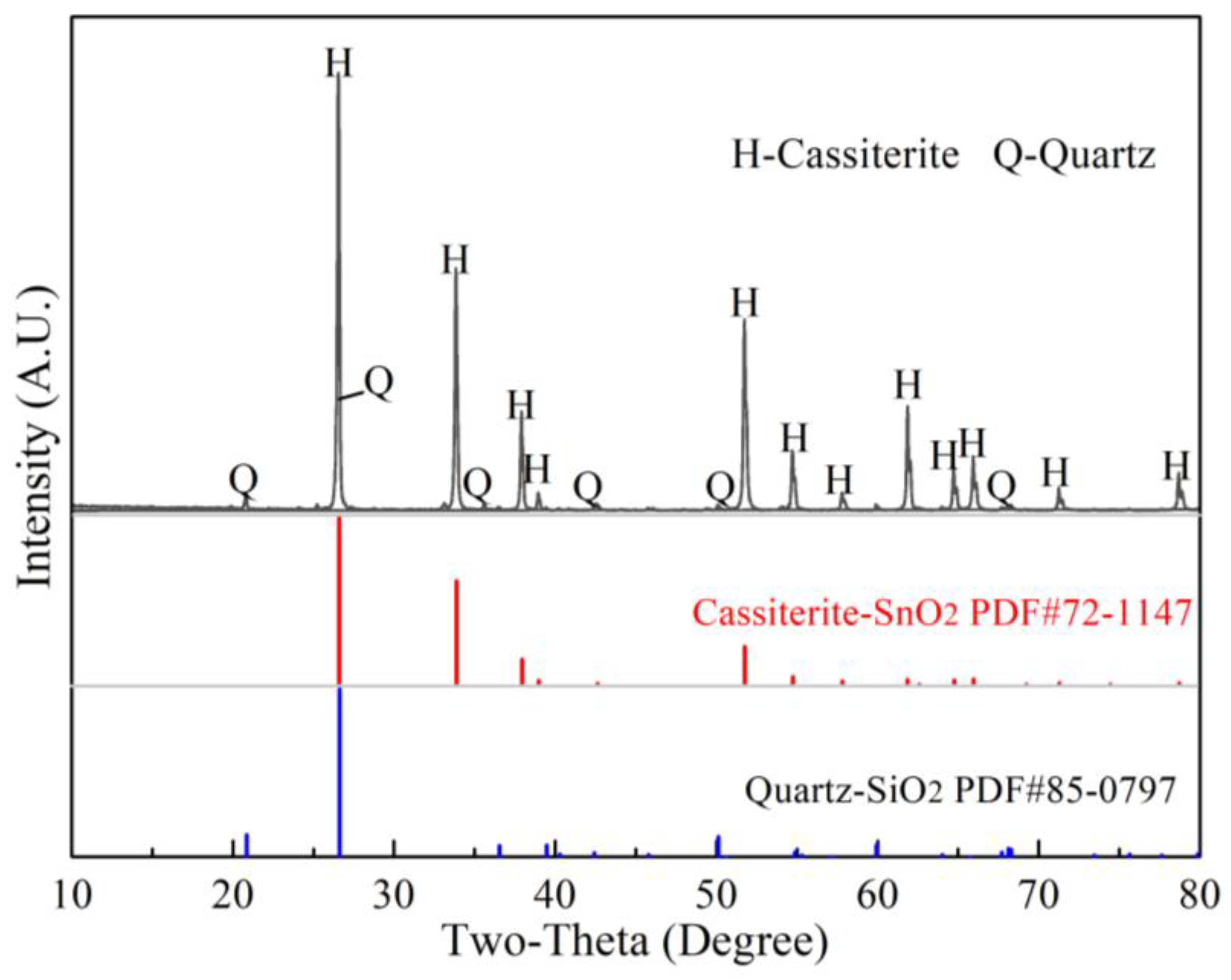
3.1. Phase Analysis for the Products of Soda Roasting

Figure 2 shows the experimental flowsheet of soda roasting and leaching using Si-bearing cassiterite concentrates. Based on a previous paper, the optimal experimental conditions were fixed at a roasting temperature of 875 °C, a CO content of 15%, roasting time of 15 min, Na2CO3/SnO2 mole ratio of 1.5, etc. [6,21]. A Sn leaching efficiency of 85.6% was achieved; moreover, a small number of leaching residues were obtained. Then, the roasted products and leaching residues (in Figure 2) were observed by XRD and SEM-EDS analysis, and the results are shown in Figure 3.
As shown in Figure 3a, the main phases in the roasted products were Na2SnO3 and Na2SiO3, which verified the high leaching efficiency of Sn and Si. In particular, the characteristic peaks of Na8SnSi6O18 were found in the leaching residues of Figure 3b, and unreacted SnO2 was observed as well. It is seen from Figure 3c that Na2SnO3 (Spot A in Figure 3c) was found as regular hexagonal cylinder crystal grains and slice crystal grains, which matched well with the theoretical molar ratio of sodium stannate of 2:1. Moreover, melting phases can be seen in the backscattering image of Figure 3c, which were formed irregularly at the grain edge of Na2SnO3. The EDS analysis of Spot B in Figure 3c showed that the main element composition was Sn, Na and Si, which is consistent with the chemical composition of Na8SnSi6O18. The morphology of leaching residues is shown in Figure 3d. The results indicated that the Na8SnSi6O18 phase (Spot C in Figure 3d) was closely wrapped in cassiterite particles. Both SnO2 and Na8SnSi6O18 were insoluble during the leaching process, and then they were enriched in the leaching residues. The results in Figure 3 indicate that Na8SnSi6O18 was rapidly formed during the roasting process, and then the melt wrapped on the surface of SnO2 and Na2CO3, which restrained the formation of Na2SnO3. It is concluded that Na8SnSi6O18 has a negative impact on the formation of sodium stannate from cassiterite. Next, the formation mechanism of Na8SnSi6O18 is discussed.

3.2. Effect of Roasting Atmospheres on the Formation of Na8SnSi6O18

To investigate the formation mechanism of Na8SnSi6O18 in the SnO2–SiO2–Na2CO3 system, AR reagents of SnO2, SiO2 and Na2CO3 were mixed at a mole ratio of Na8SnSi6O18. The XRD patterns of the samples roasted at 875 °C under a 15 vol.% CO–CO2 atmosphere and air atmosphere are shown in Figure 4.
As shown in Figure 4a, the diffraction peaks of Na8SnSi6O18 appeared remarkably, and SnO2 and SiO2 disappeared at 10 min under a CO–CO2 atmosphere. The diffraction peak intensities of Na8SnSi6O18 increased gradually as the roasting time increased from 10 min to 30 min, while those of Na2SiO3 and Na2CO3 weakened. However, the phase compositions of the roasted products in an air atmosphere were significantly different, as shown in Figure 4b, and the generation of Na8SnSi6O18 in air was much slower than that in a CO–CO2 atmosphere. Moreover, it was noteworthy that no diffraction peaks of Na2SnO3 were found in the roasted product. Our previous studies illustrated the enhancement of the CO–CO2 atmosphere on the formation of Na2SnO3, as shown in Equation (2). Hence, it can be inferred that Na2SnO3 may be an important intermediate during the formation of Na8SnSi6O18, as shown in Equation (3). Based on the above phase analysis, in a CO–CO2 atmosphere, there were stronger diffraction peaks of Na8SnSi6O18 than in an air atmosphere. The results demonstrated that the formation of Na8SnSi6O18 in the CO–CO2 atmosphere was much easier than that in the air atmosphere.
Na2CO3 + SnO2 = Na2SnO3 + CO2
SnO2 + 6SiO2 + 4Na2CO3 = Na8SnSi6O18 + 4CO2
FTIR analysis was utilized to illustrate the phase transformation of SnO2, SiO2 and Na2CO3 roasted products under a 15 vol.% CO–CO2 atmosphere, as depicted in Figure 5.
The peak at 1485 cm−1 was assigned to Si=O stretching vibrations, and vibrations at 1076 cm−1 and 932 cm−1 correspond to Si-O-Si bonds [25,26]. The results in Figure 5a,b indicate that the intensity of the Si=O bond decreased obviously as the roasting temperature and roasting time increased, which revealed the conversion of SiO2. Simultaneously, the increase in Si-O-Si bonds and Sn-O-Si/Si-O-T bonds (614 cm−1, 545 cm−1 and 449 cm−1) [25,26,27,28] can also be observed in Figure 5. The results further confirmed the molecular evolution of Si-bearing materials during the roasting process, which was consistent with the XRD analysis in Figure 4.

3.3. Effect of Intermediate Products on the Formation of Na8SnSi6O18

The results in Figure 4 demonstrate that Na2SnO3 and Na2SiO3 were generated along with Na8SnSi6O18, as shown in Equations (2) and (4), then both intermediate products were taken into consideration to reveal the reaction path for the formation of Na8SnSi6O18. SnO2 or SiO2 was first mixed with Na2CO3 at a mole ratio of 1:1 and then roasted at 875 °C under a 15 vol.% CO–CO2 atmosphere for a certain period of time. The XRD analysis of the roasted products is shown in Figure 6.
Na2CO3 + SiO2 = Na2SiO3 + CO2
As shown in Figure 6a, the reaction between SnO2 and Na2CO3 (Equation (2)) proceeded much more quickly; Na2SnO3 was the main phase in the roasted products, and almost no diffraction peaks of SnO2 were found after roasting for 15 min. In contrast, the formation rate of Na2SiO3 was slow in the solid-state, and the diffraction peaks were uncertain in Figure 6b after roasting for 30 min. The difference in the solid-state reaction rates of Equations (2) and (4) may cause different reaction paths for the final products; therefore, two possible reactions were proposed, as shown in Equations (5) and (6) based on conservation of mass.
Na2SnO3 + 6SiO2 + 3Na2CO3 = Na8SnSi6O18 + 3CO2
6Na2SiO3 + SnO2 = Na8SnSi6O18 + 2Na2O
In view of further verification, two kinds of mixed samples were prepared as follows: Na2SnO3·3H2O, Na2CO3 and SiO2 (AR reagent) with a molar ratio of 1:3:6, as shown in Equation (5), and Na2SiO3·3H2O and SnO2 with a molar ratio of 6:1 as shown in Equation (6). Then, TG-DSC (Ar atmosphere, ~1000 °C) and XRD analysis were used to determine the possible reactions in the two designed systems of Na2SnO3–SiO2 and Na2SiO3–SnO2, and the results are displayed in Figure 7 and Figure 8, respectively.
As shown in Figure 7a, two weak endothermic peaks at 87.5 °C and 243.8 °C were observed with a small quantity of weight loss, which was assigned to the thermal dehydration reaction of Na2SnO3·3H2O and Na2CO3 (crystal water) [29]. After that, the mass loss increased sharply to 18.3 wt.% with a significant endothermic peak at 833.6 °C in the DSC curve. The results revealed that the solid-phase reaction proceeded in the temperature range of 800–900 °C, the weight loss was possibility attributed to the reaction of Equation (5) and released CO2 gas. In addition, the XRD results in Figure 7b indicated that almost no diffraction peak of Na2SnO3 can be found, which illustrates that Na2SnO3 in the raw materials is converted to Na8SnSi6O18 completely, as shown in Equation (5). On the other hand, the results in Figure 8 show totally different outcomes. No exothermic reactions were found in the TG-DSC curve (in Figure 8a), and the roasted products were unchanged as SnO2 and Na2SiO3 (in Figure 8b), which excluded the reaction paths expressed in Equation (6).

3.4. Reactions between Na8SnSi6O18 and Na2CO3

To find a possible transition process of Na8SnSi6O18 during the roasting process, Na8SnSi6O18 was synthesized based on our previous study [21]. In this section, Na2CO3: SnO2: SiO2 were mixed as mole ratio of 4:1:6, with a roasting temperature of 1000 °C and roasting time of 360 min. The XRD pattern of synthetic Na8SnSi6O18 is shown in Figure 9a. The synthesized Na8SnSi6O18 was well matched with the PDF standard card of No. 85-0532, and there were no diffraction peaks of impurities. The TG-DSC analysis of Na8SnSi6O18 is given in Figure 9b. Na8SnSi6O18 was stable during the heating process, while a phase transition occurred in the temperature range of 800–850 °C with an endothermic peak at 825.6 °C in the DSC curve. A further test to determine the melting behavior of Na8SnSi6O18 using in situ high temperature thermal analysis is shown in Figure 9b. The results showed that the structure started to change when the temperature reached 800 °C, and a small amount of liquid was formed at this moment. The sample was almost fully molten into the liquid phase as the temperature increased to 825 °C. The results verified the endothermic peak in the DCS curve and corresponded to the melting point of Na8SnSi6O18.
Based on the above results, it was found that the mole ratio of Na in Na8SnSi6O18 was much lower than that of Na2SiO3/Na2SnO3, as shown in Equations (2) and (4). The reactions between Na8SnSi6O18 and Na2CO3 were discussed in the case of excess Na2CO3 dosage. Then, Na8SnSi6O18 and Na2CO3 were mixed at a mole ratio of 1:5, and TG-DSC analysis was conducted. The TG-DSC results and the XRD patterns of the roasted products are shown in Figure 10.
According to Figure 10a, obvious weight loss started from 800 °C to 950 °C, and two endothermic peaks in the DSC curve were found at 823 °C and 851 °C. The melting point of Na2CO3 was 851 °C, and it can be inferred that the mass loss was attributed to Na2CO3 decomposition in the presence of Na8SnSi6O18. It is noteworthy that, as found in Figure 10b, that Na2SiO3 and Na2SnO3 were the main phases in the final TG products, and no diffraction peak for Na8SnSi6O18 remained, which indicated that Na8SnSi6O18 easily reacted with excess Na2SnO3. A possible reaction was proposed, as shown in Equation (7), based on conservation of mass.
Na8SnSi6O18 + 3Na2CO3 = 6Na2SiO3 + Na2SnO3 + 3CO2
To verify the above analysis, the effect of roasting temperature and roasting time on the phase transformation of Na8SnSi6O18 was investigated, and the Na2CO3/Na8SnSi6O18 mole ratio was fixed at 3:1, as in Equation (6). Figure 11 shows the XRD patterns of the Na2CO3/Na8SnSi6O18 mixed samples roasted in the temperature range of 800–900 °C with a time of 30–120 min.
As shown in Figure 11a, the main phase in the roasted products was unchanged as Na8SnSi6O18 at 800 °C, while the diffraction peaks of Na2SiO3 and Na2SnO3 were uncertain. The structural diffraction peaks of Na8SnSi6O18 weakened and then vanished when the temperature exceeded 850 °C. Figure 11b shows that the diffraction peaks of Na2SiO3 appeared and Na8SnSi6O18 decreased at 30 min, and then the peaks of Na8SnSi6O18 gradually decreased and disappeared as the roasting time was prolonged to 90 min and 120 min. Na2SiO3 and Na2SnO3 were the final roasted products expressed as Equation (7).

3.5. Discussion on the Reaction Mechanism of the SnO2–SiO2–Na2CO3 System

During the soda-roasting process of cassiterite concentrates, the overriding aim was to synchronously promote the transformation of stubborn minerals (SnO2 and SiO2) into freely soluble materials (Na2SnO3 and Na2SiO3). However, Na8SnSi6O18 was inevitably generated during the roasting process, which was almost insoluble in the leaching process and markedly decreased the recovery of Sn. Based on the above results and our previous studies, the reaction mechanism of the SnO2–SiO2–Na2CO3 system and the formation of Na8SnSi6O18 can be summarized as follows in Figure 12.
First, SnO2 reacted with Na2CO3 to form Na2SnO3 as shown in Equation (2). Meanwhile, part of SiO2 also reacted with Na2CO3 to form a small amount of Na2SiO3, see Equation (4). Nonetheless, the reaction rate was much lower than that of Equation (2). Then, Na2SnO3 reacted immediately with Na2CO3 and SiO2 to form Na8SnSi6O18 as shown in Equation (5), and Na2SnO3 was the key intermediate during the formation of Na8SnSi6O18, while the reaction between Na2SiO3 and SnO2 was impossible. The melting point of Na8SnSi6O18 was measured at 825 °C, which was much lower than that of other materials in the SnO2–SiO2–Na2CO3 system. Thus, Na8SnSi6O18 was always formed accompanied by SnO2 and invariably closely wrapped around SnO2 particles, which blocked the contact between SnO2 and Na2CO3. Therefore, the formation of Na2SnO3 was significantly inhibited once Na8SnSi6O18 was present. In addition, Na8SnSi6O18 is an unstable compound that can react with excess Na2CO3 (Equation (7)) as the roasting temperature and time increase.

4. Conclusions

During the process of sodium stannate preparation from cassiterite concentrate under a CO–CO2 atmosphere, the formation of Na8SnSi6O18 in the SnO2–SiO2–Na2CO3 system affects the quality of sodium stannate products. To solve this problem, the effects of Na8SnSi6O18 formation on the product quality were investigated in this study, and the following conclusions were obtained:
  • The reactions between Na2CO3 and SnO2/SiO2 proceeded simultaneously during the roasting process, while the formation of Na2SnO3 was promoted under a CO–CO2 atmosphere. Then, Na8SnSi6O18 was easily formed once Na2SnO3 appeared; nonetheless, the reaction between Na2SiO3 and SnO2 was impossible;
  • The melting point of Na8SnSi6O18 is only 825 °C, which is much lower than that of Na2CO3, Na2SnO3 and Na2SiO3 in the SnO2–SiO2–Na2CO3 system. Na8SnSi6O18 closely wrapped around the SnO2 particles and restrained the reaction between SnO2 and Na2CO3;
  • Na8SnSi6O18 is an unstable compound, and the reaction between Na8SnSi6O18–Na2CO3 can proceed as Na8SnSi6O18 + 3Na2CO3 = 6Na2SiO3 + Na2SnO3 + 3CO2. The reaction was controlled by higher temperatures of above 800 °C as the roasting time was prolonged.

Author Contributions

Methodology, Writing—original draft, Z.S.; Writing—review and editing, Data curation, S.L.; Data curation, B.H.; Writing—review and editing, Supervision, Y.Z.; Conceptualization, Writing—review and editing, T.J. All authors have read and agreed to the published version of the manuscript.

Funding

This research was funded by National Natural Science Foundation of China, grant number No. 51904353 and No. 51574283.

Institutional Review Board Statement

Not applicable.

Informed Consent Statement

Not applicable.

Data Availability Statement

The data presented in this study are available on request from the corresponding author.

Conflicts of Interest

The authors declare no conflict of interest. No experiments on live vertebrates and/or higher invertebrates were performed in this manuscript.

References

  1. Yin, T.T.; Lee, J.; Moosavi-Khoonsari, E.; Jung, I.-H. Critical evaluation and the thermodynamic optimization of the Sn-O system. Ceram. Int. 2021, 47, 29267–29276. [Google Scholar] [CrossRef]
  2. Wright, P.A. Extractive Metallurgy of Tin, 2nd ed.; Elsevier Scientific Publishing Company Press: New York, NY, USA, 1982. [Google Scholar]
  3. Sharma, A.; Das, S.; Das, K. Effect of different electrolytes on the microstructure, corrosion and whisker growth of pulse plated tin coatings. Microelectron. Eng. 2017, 170, 59–68. [Google Scholar] [CrossRef]
  4. Wang, Y.R.; Tang, R.J.; Yang, C.H.; Xu, T.Y.; Mitsuzaki, N.; Chen, Z.D. Effect of sodium stannate on low temperature electroless Ni-Sn-P deposition and the study of its mechanism. Thin Solid Film. 2019, 669, 72–79. [Google Scholar] [CrossRef]
  5. Zhang, S.G.; Wei, Y.D.; Yin, S.F.; Luo, S.L.; Au, C.T. Superbasic sodium stannate as catalyst for dehydrogenation, Michael addition and transesterification reactions. Appl. Catal. A-Gen. 2011, 406, 113–118. [Google Scholar] [CrossRef]
  6. Zhang, Y.B.; Su, Z.J.; Liu, B.B.; You, Z.X.; Li, G.H.; Jiang, T. Sodium stannate preparation from stannic oxide by a novel soda roasting—Leaching process. Hydrometallurgy 2014, 146, 82–88. [Google Scholar] [CrossRef]
  7. Liu, B.B.; Zhang, Y.B.; Su, Z.J.; Li, G.H.; Jiang, T. Function mechanism of CO-CO2 atmosphere on the formation of Na2SnO3 from SnO2 and Na2CO3 during the roasting process. Powder Technol. 2016, 301, 102–109. [Google Scholar] [CrossRef]
  8. Zhang, Y.B.; Liu, B.B.; Su, Z.J.; Chen, J.; Li, G.H.; Jiang, T. Effect of Na2CO3 on the preparation of metallic tin from cassiterite roasted under strong reductive atmosphere. J. Min. Met. Sect. B Met. 2016, 52, 9–15. [Google Scholar] [CrossRef]
  9. Liu, B.B.; Zhang, Y.B.; Su, Z.J.; Li, G.H.; Jiang, T. Phase evolution of tin oxides roasted under CO-CO2 atmospheres in the presence of Na2CO3, Miner. Process. Extr. Met. Rev. 2016, 37, 264–273. [Google Scholar] [CrossRef]
  10. Liu, B.B.; Zhang, Y.B.; Su, Z.J.; Li, G.H.; Jiang, T. Formation kinetics of Na2SnO3 from SnO2 and Na2CO3 roasted under CO-CO2 atmosphere. Int. J. Miner. Process. 2017, 165, 34–40. [Google Scholar] [CrossRef]
  11. Liu, W.; Li, W.H.; Han, J.W.; Wu, D.X.; Li, Z.H.; Gu, K.H.; Qin, W.Q. Preparation of calcium stannate from lead refining slag by alkaline leaching-purification-causticization process. Sep. Purif. Technol. 2019, 212, 119–125. [Google Scholar] [CrossRef]
  12. Wu, D.X.; Liu, W.; Han, J.W.; Jiao, F.; Xu, J.H.; Gu, K.H.; Qin, W.Q. Direct preparation of sodium stannate from lead refining dross after NaOH roasting-water leaching. Sep. Purif. Technol. 2019, 227, 115683. [Google Scholar] [CrossRef]
  13. Liu, W.; Li, Z.H.; Han, J.W.; Li, W.H.; Wang, X.; Wang, N.; Qin, W.Q. Selective Separation of Arsenic from Lead Smelter Flue Dust by Alkaline Pressure Oxidative Leaching. Minerals 2019, 9, 308. [Google Scholar] [CrossRef] [Green Version]
  14. Wu, D.X.; Han, J.W.; Liu, W.; Jiao, F.; Qin, W.Q. Preparation of Calcium Stannate from Lead Refining Dross by Roast–Leach–Precipitation Process. Minerals 2019, 9, 283. [Google Scholar] [CrossRef] [Green Version]
  15. Angadi, S.I.; Sreenivas, T.; Jeon, H.; Baek, S.; Mishra, B.K. A review of cassiterite beneficiation fundamentals and plant practices. Miner. Eng. 2015, 70, 178–200. [Google Scholar] [CrossRef]
  16. Llorens González, T.; Polonio, F.G.; LópBez Mornito, F.J.; Fernández, A.F.; Contreras, J.L.S.; Moro Benito, M.C. Tin-tantalum-niobium mineralization in the Penouta deposit (NW Spain): Textural features and mineral chemistry to unravel the genesis and evolution of cassiterite and columbite group minerals in a peraluminous system. Ore Geol. Rev. 2017, 81, 79–95. [Google Scholar] [CrossRef]
  17. Sami, M.; Ntaflos, T.; Mohamed, H.A.; Farahat, E.S.; Hauzenberger, C.; Mahdy, N.M.; Abdelfadil, K.M.; Fathy, D. Origin and Petrogenetic Implications of Spessartine Garnet in Highly-Fractionated Granite from the Central Eastern Desert of Egypt. Acta Geol. Sin. Engl. Ed. 2020, 94, 763–776. [Google Scholar] [CrossRef]
  18. Sami, M.; El Monsef, M.A.; Abart, R.; Toksoy-Köksal, F.; Abdelfadil, K.M. Unraveling the Genesis of Highly Fractionated Rare-Metal Granites in the Nubian Shield via the Rare-Earth Elements Tetrad Effect, Sr–Nd Isotope Systematics, and Mineral Chemistry. ACS Earth Space Chem. 2022, 6, 2368–2384. [Google Scholar] [CrossRef]
  19. Su, Z.J.; Zhang, Y.B.; Liu, B.B.; Zhou, Y.L.; Jiang, T.; Li, G.H. Reduction behavior of SnO2 in the tin-bearing iron concentrates under CO-CO2 atmosphere. Part I: Effect of magnetite. Powder Technol. 2016, 292, 251–259. [Google Scholar] [CrossRef]
  20. Su, Z.J.; Zhang, Y.B.; Liu, B.B.; Lu, M.M.; Li, G.H.; Jiang, T. Extraction and Separation of Tin from Tin-Bearing Secondary Resources: A Review. JOM 2017, 69, 2364–2372. [Google Scholar] [CrossRef]
  21. Zhang, Y.B.; Han, B.L.; Su, Z.J.; Chen, X.J.; Lu, M.M.; Liu, S.; Liu, J.C.; Jiang, T. Effect of Quartz on the Preparation of Sodium Stannate from Cassiterite Concentrates by Soda Roasting Process. Minerals 2019, 9, 605. [Google Scholar] [CrossRef]
  22. Lee, J.; Yin, T.T.; Hudon, P.; Jung, I.-H. Phase diagram study of the SnO2-SiO2 system and thermodynamic optimization of the SnO-SnO2-SiO2 system. Ceram. Int. 2021, 48, 4141–4152. [Google Scholar] [CrossRef]
  23. El-Agawany, F.I.; Tashlykov, O.L.; Mahmoud, K.A.; Rammah, Y.S. The radiation-shielding properties of ternary SiO2-SnO-SnF2 glasses: Simulation and theoretical study. Ceram. Int. 2020, 46, 23369–23378. [Google Scholar] [CrossRef]
  24. Kang, J.R.; Gu, R.; Guo, X.; Li, J.; Sun, H.C.; Zhang, L.Y.; Jing, R.Y.; Jin, L.; Wei, X.Y. Effect of SnO-P2O5-MgO glass addition on the ionic conductivity of Li1.3Al0.3Ti1.7(PO4)3 solid electrolyte. Ceram. Int. 2021, 48, 157–163. [Google Scholar] [CrossRef]
  25. Song, L.; Liu, W.H.; Zhao, K.B.; Xin, F.H.; Li, Y.M. Effects of water and carbon dioxide pressure on the adhesion of Na2SiO3 and K2SiO3 binders on silica sand surface: Comparison of experimental data and molecular dynamics simulation. Ceram. Int. 2021, 47, 32648–32656. [Google Scholar] [CrossRef]
  26. Xia, Y.D.; Mokaya, R. On the synthesis and characterization of ZSM-5/MCM-48 aluminosilicate composite materials. J. Mater. Chem. 2004, 14, 863–870. [Google Scholar] [CrossRef]
  27. Niphadkar, P.S.; Garade, A.C.; Jha, R.K.; Chandrashekhar, V.R.; Praphulla, N.J. Micro-/meso-porous stannosilicate composites (Sn-MFI/MCM-41) via two-step crystallization process: Process parameter-phase relationship. Microporous Mesoporous Mater. 2010, 136, 115–125. [Google Scholar] [CrossRef]
  28. Lin, Z.; Rocha, J. Synthesis and characterisation of a stannosilicate with the structure of penkvilksite-1 M. Microporous Mesoporous Mater. 2006, 94, 173–178. [Google Scholar] [CrossRef]
  29. Santos, T.G.; Silva, A.O.S.; Meneghetti, S.M.P. Comparison of the hydrothermal syntheses of Sn-magadiite using Na2SnO3 and SnCl4·5H2O as the precursors. Appl. Clay Sci. 2019, 183, 105293. [Google Scholar] [CrossRef]
Figure 1. XRD patterns of Si-bearing cassiterite concentrates.
Materials 15 08718 g001
Figure 2. The flowsheet for preparing sodium stannate from Si-bearing cassiterite concentrates.
Materials 15 08718 g002
Figure 3. Phase analysis of the roasting products and the leaching residues. ((a)-XRD results of roasted products, (b)-XRD results of leaching residues, (c)-SEM analysis of the roasted products, (d)-SEM analysis of leaching residues).
Materials 15 08718 g003
Figure 4. Effect of atmosphere on the formation of Na8SnSi6O18 (at 875 °C).
Materials 15 08718 g004
Figure 5. FTIR spectra of SnO2, SiO2 and Na2CO3 roasted products under 15 vol.% CO–CO2 atmosphere.
Materials 15 08718 g005
Figure 6. Reactions of SnO2–Na2CO3 and SiO2–Na2CO3 systems (875 °C).
Materials 15 08718 g006
Figure 7. Reactions between Na2SnO3·3H2O and SiO2 ((a)-TG-DSC analysis, (b)-XRD analysis of the TG products).
Materials 15 08718 g007
Figure 8. Reactions between Na2SiO3 and SnO2 ((a)-TG DSC analysis, (b)-XRD analysis of the TG products).
Materials 15 08718 g008
Figure 9. Properties of synthetic Na8SnSi6O18 ((a)-XRD patterns, (b)-TG-DSC analysis).
Materials 15 08718 g009
Figure 10. Reactions between Na8SnSi6O18 and Na2CO3 ((a)-TG-DSC analysis, (b)-XRD analysis of the TG products).
Materials 15 08718 g010
Figure 11. Effect of roasting temperature and time on the reaction between Na8SnSi6O18 and Na2CO3.
Materials 15 08718 g011
Figure 12. Phase evolution in the SnO2–SiO2–Na2CO3 system during soda roasting process.
Materials 15 08718 g012
Publisher’s Note: MDPI stays neutral with regard to jurisdictional claims in published maps and institutional affiliations.

