Abstract
Hydrogen is the alternative renewable energy source for addressing the energy crisis, global warming, and climate change. Hydrogen is mostly obtained in the industrial process by steam reforming of natural gas. In the present work, CuCrO2 particles were attached to the surfaces of electrospun CeO2 nanofibers to form CeO2-CuCrO2 nanofibers. However, the CuCrO2 particles did not readily adhere to the surfaces of the CeO2 nanofibers, so a trace amount of SiO2 was added to the surfaces to make them hydrophilic. After the SiO2 modification, the CeO2 nanofibers were immersed in Cu-Cr-O precursor and annealed in a vacuum atmosphere to form CeO2-CuCrO2 nanofibers. The CuCrO2, CeO2, and CeO2-CuCrO2 nanofibers were examined by X-ray diffraction analysis, transmission electron microscopy, field emission scanning electron microscopy, scanning transmission electron microscope, thermogravimetric analysis, and Brunauer–Emmett–Teller studies (BET). The BET surface area of the CeO2-CuCrO2 nanofibers was 15.06 m2/g. The CeO2-CuCrO2 nanofibers exhibited hydrogen generation rates of up to 1335.16 mL min−1 g-cat−1 at 773 K. Furthermore, the CeO2-CuCrO2 nanofibers produced more hydrogen at lower temperatures. The hydrogen generation performance of these CeO2-CuCrO2 nanofibers could be of great importance in industry and have an economic impact.
1. Introduction
Hydrogen is a viable renewable energy source for addressing the threat of global warming and the decline of fossil fuels. Fuel cells are one of the latest technologies that may effectively convert chemicals into electrical energy to reduce these pollutants [1,2]. Proton-exchange membrane fuel cells (PEMFCs) in particular are systems with zero pollution emissions because they convert chemical energy into electrical energy during the electrochemical reaction of hydrogen and oxygen. Because the anodic Pt-based catalyst can only take less than 10 ppm of CO, PEMFCs typically require a supply of high-purity hydrogen [3,4]. Several methods can be used to produce hydrogen, but the main one is the steam reforming of natural gas. However, the use of hydrogen poses challenges in terms of production and storage [5,6]. The use of steam reforming of methanol (SRM) to produce hydrogen will effectively solve the above problems. SRM has attracted attention because of its low-temperature need for reaction, water-solubility, endothermic process, and high hydrogen yields, which make it ideal for fuel cell applications [7,8]. Decomposition, steam reforming, and partial oxidation are the three primary methods utilized to produce hydrogen from CH3OH [9,10].
CH3OH → CO + 2H2………………………….... ΔH0 = 128 kJ/mol
CH3OH + H2O → CO2 + 3H2……………………ΔH0 = 131 kJ/mol
CH3OH + ½O2 → CO2 + 2H2……………………ΔH0 = 155 kJ/mol
At a high CO ratio, the decomposition process is an extremely endothermic breakdown process. As a result, this method is ineffective for fuel cells [11]. The partial oxidation reaction process is a highly exothermic reaction with 66% hydrogen output. This process uses pure oxygen instead of air. Finally, the endothermic steam reforming process produces a high rate of hydrogen, up to 75% on a dry basis, with CO as a byproduct. As a result, the steam reforming process is more advantageous for hydrogen production [12,13]. These traditional methods for converting SRM into hydrogen comprise processes like CH3OH decomposition, water gas shift, and the SRM process [14].
The SRM process is appropriate for producing hydrogen due to its low reaction temperature, adequate water miscibility, high hydrogen concentration ratio, and low CO level. It is also a direct and cost-effective method of hydrogen production. In addition, it is endothermic and can produce a large amount of hydrogen, which is favorable for fuel cell usage [15,16].
The performance of steam re-forming at the reactor is highly impacted by the reaction conditions and catalyst preparation. In the SRM reaction, Ru, Zn, Pd, Ni, Cu, and a combination of these metal-based catalysts are frequently used. Cu-based catalysts are particularly suitable for hydrogen production in the SRM process. Copper and copper-based catalyst materials have a high operating temperature of 573 K, although deactivation occurs at 573–623 K due to the thermal frittage of Cu particles. A further key issue with the SRM process is the deactivation of the catalyst due to the deposition of carbon particles on the Cu catalyst surface [17,18].
To alleviate these issues, a metallic oxide such as ZrO2, Fe2O, ZnO, and CeO2 can be combined with copper and copper-based catalysts to enhance the catalytic performance. With the metallic oxide, the enhanced Cu catalyst will have a fine dispersion with high efficiency and thermal stability. Catalysts have a big impact on the formation of hydrogen in the SRM reaction and the final products. Hence, metal oxide catalysts like Al2O3, ZnO/Al2O3, ZrO2/Al2O, Cr2O3/Al2O3, CuO/ZnO/Al2O3, and CeO2/ZrO2 are used as a catalyst for the SRM reaction [19,20]. However, the primary issue with the SRM process is the deposition of carbon particles on the surface of the Cu-related catalyst, which lowers the catalyst’s effectiveness. To improve the efficiency of hydrogen production, many studies have focused on the use of delafossite materials in the SRM process [21,22].
The chemical formula of delafossite is ABO2, where A is a cation with linear coordination to two oxygen ions that are often occupied by a cation of a noble metal with a univalent oxidation state, such as Pt1+, Cu1+, or Ag1+. The central metal of the distorted edge-shared BO6 octahedron is cation B, which has a trivalent charge, such as B3+, Al3+, Ga3+, Cr3+, or Fe3+. Delafossite is a translucent conductive oxide applied in optoelectronic technology [23,24,25]. However, research regarding its application to catalysis has been scant. Previous studies have applied it to methanol synthesis, N2O decomposition [26], methanol steam reforming [27], HCl oxidation [28], photocatalytic hydrogen processing, and NO3 elimination, among other things [29].
Cerium oxide has numerous applications, some being catalysis, ceramics, gas sensors, fuel cell, biomaterials, and solid electrolytes [30]. The most important characteristic of CeO2 is that it transfers oxygen via the redox potential transfer between Ce4+ and Ce3+ under oxidation and reduction conditions [31]. Li et al. have reported that adding CeO2 can reduce the catalytic temperature of Cu-based catalysts and promote catalytic efficiency [32]. Electrospinning was first patented in the United States in 1902 by John Francis Cooley [33]. This method can produce one-dimensional fibers in the micrometer to nanometer diameter ranges with large active surface areas and high porosity. Oxide nanofibers have already been used in energy and environmental applications, such as sensors, catalysis, biotechnology, solar cells, hydrogen energy, and super-capacitors [34].
The CeO2-CuCrO2 nanofiber catalyst was synthesized by the self-combustion glycine–nitrate process (GNP) and applied for SRM in this study. The CeO2-CuCrO2 nanofibers had a nanosized, spherical shape with a crystalline delafossite structure. Furthermore, the hydrogen production rate of CeO2-CuCrO2 nanofibers was compared with those of CuCrO2, CeO2, and commercial Cu/Al/Zn catalysts. Based on the comparison, the CeO2-CuCrO2 nanofibers exhibited higher hydrogen yields with lower coke formation during the SRM process as compared with CuCrO2, CeO2, and commercial Cu/Al/Zn catalysts.
2. Materials and Methods
2.1. Instrumentation
The starting reagents, namely copper nitrate hexahydrate ([Cu(NO3)3·6H2O]), chromium nitrate nonahydrate ([Cr(NO3)3·9H2O]), cerium nitrate hexahydrate ([Ce(NO3)3·6H2O]), N, N-dimethylformamide, Triton X100 polyvinylpyrrolidone (PVP) (M. W = 1,300,000 g·mol−1), and tetraethyl orthosilicate (TEOS), were obtained from SHOWA and Sigma-Aldrich. In this study, the CeO2 nanofibers and CeO2-CuCrO2 nanofibers were examined using the appropriate instrumentation techniques. By using an X-ray diffractometer (D2 Phaser, Bruker) with a working voltage of 30 kV and CuK radiation, the crystalline structures of the nanofibers were examined. Field emission scanning electron microscopy (FESEM) (Regulus-8100, HITACHI, Tokyo, Japan) and transmission electron microscopy studies (FE-2100TEM, JEOL, Tokyo, Japan) were used in this work to examine the morphology and particle size of the catalyst. A thermogravimetric analysis/differential scanning calorimeter (TGA/DSC, STA 449 F5, NETZSCH, Selb, Germany) was used to investigate the thermal degradation behavior of electrospun fibers. The specific surface area was calculated using the Brunauer–Emmett–Teller (BET) method using a Micromeritics TriStar II 3030 specification. Before a BET measurement was performed, an appropriate quantity of the produced catalyst was de-gassed at 473 K for 24 h to eliminate the absorbed water. At different relative pressures (P/P0) ranging from 0 to 0.3, N2 adsorption isotherms were observed and examined while the catalyst absorbed N2.
2.2. Preparation of CeO2 Nanofibers
The precursor solution was synthesized by dissolving 0.625 g of cerium nitrate in 14.4 mL of N, N-dimethylformamide. Following that, 2.4 g of PVP was dissolved in the above precursor solution. After 6 h of stirring, a bright yellow viscous gel-like reaction precursor solution was obtained. This solution was electrospun with a working distance of 15 cm, a voltage of 18 kV, a flow rate of 0.02 mL/h, temperature controlled at 313 K, and humidity of less than 20%. The as-spun fiber was annealed at 873 K with a heating rate of 274 K per minute, and the resulting CeO2 nanofibers were analyzed by XRD and SEM studies.
2.3. Surface Modification of CeO2 Nanofibers
The surfaces of the CeO2 nanofibers were modified as follows. Because CuCrO2 would not easily adhere directly to the surfaces of the CeO2 nanofibers, the surfaces were coated with SiO2. Hence, the CeO2 fibers were dipped into tetraethyl orthosilicate (TEOS) and then annealed in air at 873 K. The modified CeO2 nanofibers were analyzed by XRD, SEM, and TEM studies.
2.4. Preparation of CeO2 Nanofibers Decorated with CuCrO2 Nanoparticles (CeO2-CuCrO2)
CeO2 nanofibers decorated with CuCrO2 nanoparticles (CeO2-CuCrO2) were prepared with the following procedure. The CeO2 fibers were dipped in the precursor, which was a mixture of methanol, chromium nitrate, copper nitrate, and Triton X100, and then dried at 353 K for 2 min before being annealed at 1073 K in a vacuum with a heating rate of 283 K per minute. The prepared CeO2-CuCrO2 nanofibers were analyzed by XRD, SEM, and TEM.
2.5. Steam Reforming of Methanol Process over Electrospun CeO2-CuCrO2 Nanofibers Catalyst
The steam reforming of methanol was performed in a tubular flow reactor using a 25 cm quartz tube with a 1.2 cm inner diameter, nitrogen as the carrier gas with a flow rate of 30 sccm, and 20 mg of catalyst per SRM reaction. The system was connected to a gas chromatograph for analysis. A methanol–water mixture was prepared in a 3:1 molar ratio and heated to 353 K on a hot plate to evaporate methanol–water vapor. A gas tube was inserted into the Erlenmeyer flask beneath the level of the methanol aqueous solution, and then the methanol vapor was carried by nitrogen to the catalyst for the reaction. The nanofibers were sandwiched between quartz cotton in the middle of the quartz tube and then heated to 523, 573, 623, 673, 723, and 773 K, respectively. A gas chromatograph (GC 1000 China Chromatography TCD) was used to analyze each temperature and identify the average values (Figure 1).
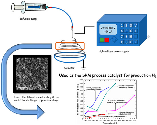
Figure 1.
Schematic diagram of the methanol steam reforming process on the electrospun CeO2-CuCrO2 nanofibers catalyst.
3. Results and Discussion
3.1. XRD Analysis
The prepared nanofiber diffraction patterns and crystal structures were studied by XRD studies and analyzed with powder X-ray diffractometric MDI JADE5.0 software tools. Figure 2a presents the XRD pattern of CeO2 nanofibers, showing the pure CeO2 cubic phase (JCPDS card PDF#34-0394.) After the electrospun CeO2 nanofibers were annealed at high temperature, the cerium nitrate decomposed and CeO2 remained.
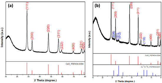
Figure 2.
XRD patterns of (a) CeO2 and (b) CeO2-CuCrO2 nanofibers.
Figure 2b shows the XRD pattern of CuCrO2-coated CeO2 nanofibers. The XRD spectra of CeO2-CuCrO2 nanofibers exhibited that CuCrO2 nanoparticles were attached to the CeO2 nanofibers. The XRD pattern reveals CeO2 (PDF#34-0394) and CuCrO2 (PDF#39-0247) phases on the CeO2-CuCrO2 nanofibers. The XRD pattern of CeO2 nanofibers after SiO2 surface modification only reveals CeO2 (PDF#34-0394) due to annealing at 873 K and its SiO2 content being too low.
Figure 3 shows the XRD pattern of CeO2-CuCrO2 after SRM at different temperatures. From the XRD pattern, it can be observed that when the catalytic temperature increases, the peak of CuCrO2(101) at 2θ = 35.178°(PDF#39-0247) gradually disappears. At 773 K, due to the precipitation of CuCrO2 after catalysis, the peaks of the copper (111) and (200) planes can be observed at 2θ = 43.297° and 50.433° (PDF#04-0836), respectively.
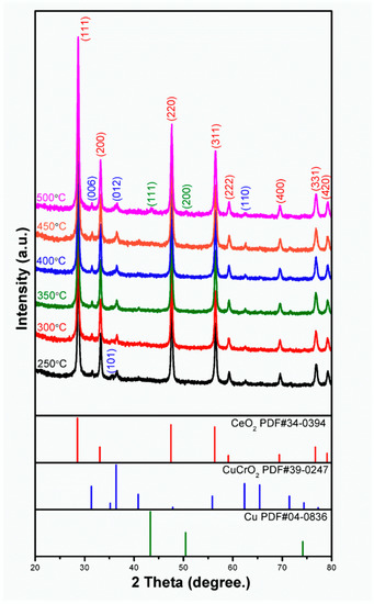
Figure 3.
XRD pattern of CeO2-CuCrO2 nanofibers after SRM at different temperatures.
3.2. FESEM Analysis
The morphologies of the CeO2 nanofibers and CeO2-CuCrO2 nanofibers were identified by FESEM and TEM studies. Figure 4 shows the FESEM image of electrospun CeO2 and CeO2-CuCrO2 nanofibers. Figure 4a,b show the CeO2 nanofibers after annealing at a rate of 274 K/min to 873 K in an air atmosphere. The CeO2 nanofibers decreased in size by about 110 nm and disappear from PVP due to annealing. Figure 4c,d show FESEM images of CeO2-CuCrO2 nanofibers. It was found that CuCrO2 is difficult to directly attach to the surface of CeO2; therefore, the surface was modified with SiO2 to improve the CuCrO2 adherence. The FESEM images show that the CeO2-CuCrO2 nanofibers were very thin, with diameters similar to those of the CeO2 nanofibers.
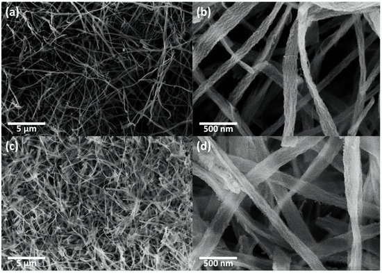
Figure 4.
FESEM image of (a,b) CeO2 nanofibers and (c,d) CeO2-CuCrO2 nanofibers.
Figure 5 shows the FESEM images of CeO2-CuCrO2 after SRM at different temperatures. The morphologies of CeO2-CuCrO2 nanofibers after SRM at 523–623 K exhibited the fiber structure, revealing that the CeO2-CuCrO2 nanofibers had better stability at lower reaction temperatures, as can be seen in Figure 5a–c. Figure 5d shows that the morphology of the nanofibers becomes more fragmented when the catalytic temperature reaches 673 K. From Figure 5e,f, it can be observed that when the catalytic temperature reaches 723 K, copper-precipitated particles begin to appear on the surface of the nanofibers. When the catalytic temperature reaches 773 K, the precipitated particles are scattered on the surface.
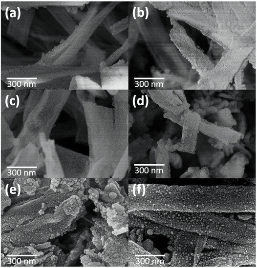
Figure 5.
FESEM images of CeO2-CuCrO2 nanofibers after SRM at different temperatures (a) 523 K, (b) 573 K, (c) 623 K, (d) 673 K, (e) 723 K, and (f) 773 K.
3.3. TEM and STEM-EDS Analysis
Figure 6a,b shows TEM images of CeO2-CuCrO2 nanofibers. These images confirmed that the CuCrO2 particles were arranged and attached to the surface of CeO2 nanofibers. The STEM image in Figure 7a confirmed that the CeO2 nanofibers had particles arranged on the surface and attached to them. The particle attached to the fiber were investigated by STEM-EDS mapping. The STEM-EDS mapping confirmed the presence of (b) Ce, (c) Si, (d) O, (e) Cu, and (f) Cr in the CeO2-CuCrO2 nanofibers. Figure 7g shows the overall STEM-EDS mapping, which confirmed the presence of Ce, Si, O, Cu, and Cr in the CeO2-CuCrO2 nanofibers. Figure 8 shows the STEM-EDS results of modified CeO2 nanofibers coated with CuCrO2. Figure 8a confirms the presence of Ce, Si, O, Cu, and Cr in the CeO2-CuCrO2 nanofibers. The STEM-EDS spectra of CeO2-CuCrO2 nanofibers after SiO2 surface modification show that (b) Ce, (c) Si, (d) O, (e) Cu, and (f) Cr were present in the CeO2-CuCrO2 nanofibers. Figure 8g shows the STEM-EDS overall spectra confirming that the layer on the fiber surface was mainly composed of CeO2-CuCrO2. Hence, TEM and STEM-EDS studies confirmed the formation of CeO2-CuCrO2 nanofibers.
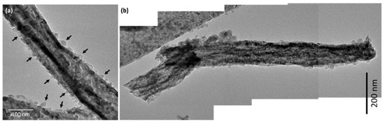
Figure 6.
(a,b) TEM image of CeO2-CuCrO2 nanofiber.
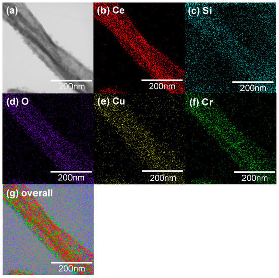
Figure 7.
(a) STEM image of CeO2-CuCrO2 nanofiber, (b) Ce, (c) Si, (d) O, (e) Cu, (f) Cr. (g) Overall STEM-EDS mapping of Ce, Si, O, Cu and Cr present in CeO2-CuCrO2 nanofiber.
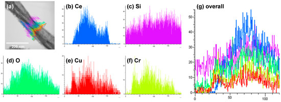
Figure 8.
STEM image of CeO2-CuCrO2 nanofibers. (a) Overall STEM spectrum of Ce, O, Si, Cu, and Cr overlap; Elemental mapping of (b) Ce, (c) Si, (d) O, (e) Cu, (f) Cr. (g) Overall STEM-EDX spectrum of Ce, O, Si, Cu, and Cr overlap.
3.4. TGA Analysis
To observe the decomposition mechanism of the as-spun nanofibers at high temperatures, a simultaneous thermogravimetric analyzer was used to observe the TGA/DSC curve, and the temperature was increased to 873 K at a rate of 283 K per minute in air. Figure 9 shows the TGA/DSC curve of electrospun CeO2-CuCrO2 fibers. According to the TGA/DSC studies, the weight loss before 373 K is due to the volatilization of the remaining water in the CeO2-CuCrO2 fibers. The slight weight loss at approximately 423 K and the exothermic slope are due to DMF decomposition, and the endothermic peak at around 493 K is due to cerium nitrate decomposition. After that, a massive and continuous weight loss at about 523 K indicates the significant decomposition of PVP. Moreover, at 573 K to 673 K, an endothermic peak signals the formation of CeO2-CuCrO2 nanofibers.
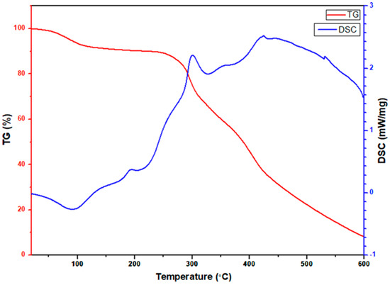
Figure 9.
TGA/DSC studies of electrospun CeO2-CuCrO2 nanofibers.
3.5. Specific Surface Area Analysis
The specific surface area of the CeO2-CuCrO2 nanofibers is listed in Table 1. Table 1 shows the BET-specific surface areas of delafossite materials produced by solid-state reaction, glycine combustion, and electrospinning. The specific surface area of the CeO2-CuCrO2 nanofibers produced in this experiment is 15.06 m2/g, which is larger than the specific surface area of solid-state reactions and other electrospun products.

Table 1.
Specific surface area of the different delafossite materials prepared by various processes.
3.6. Steam Reforming of Methanol Performance
A gas chromatograph was attached to the thermal conductivity detector and used for measuring the rate of hydrogen production. At a flow velocity of 30 sccm and temperatures between 523 K and 773 K, the hydrogen generation was measured using 0.04 g of catalyst, and the hydrogen production rate was converted into mL min−1 g-cat−1. To obtain high catalytic performance, the prepared CeO2-CuCrO2 catalyst was heated without contact with methanol vapor. Additionally, the carrier gas was altered so that the system was filled with methanol steam, and the gas coming from the exit tube was located. As shown in Table 2, the SRM process was carried out over the CeO2-CuCrO2 catalysts at 523–673 K at a flow rate of 30 sccm. Additionally, when the reaction temperature was raised from 523–673 K, the rate of hydrogen generation increased. The results are shown in Figure 10. In Figure 10, the CeO2-CuCrO2 nanofiber exhibited an excellent hydrogen production performance compared with CuCrO2 (solid-state method) and commercial Cu/Zn/Al catalysts [24,35]. Table 2 shows the hydrogen production rate of CeO2-CuCrO2 nanofibers at different temperatures—the hydrogen production rises with an increase in temperature. However, the CeO2-CuCrO2 nanofibers lose their activity at the reaction temperature is too high, therefore the experiment has not been continued to a high temperature. The CeO2-CuCrO2 nanofibers are extremely stable in air, in contrast to an H2-activated catalyst, which is typically harmful when exposed to air due to its high activity and potential for ignition and explosion. Therefore, there is no need to activate the CeO2-CuCrO2 nanofiber catalyst at high temperatures for the SRM process. This study implies that greater efficiency can be attained than with traditional catalysts if CeO2-CuCrO2 nanofibers are installed in a fuel cell vehicle. Future research will examine the stability of the catalyst, SRM conditions, and reactor condition optimization.
Table 2.
Hydrogen production rate of CeO2-CuCrO2 nanofibers at different temperatures.
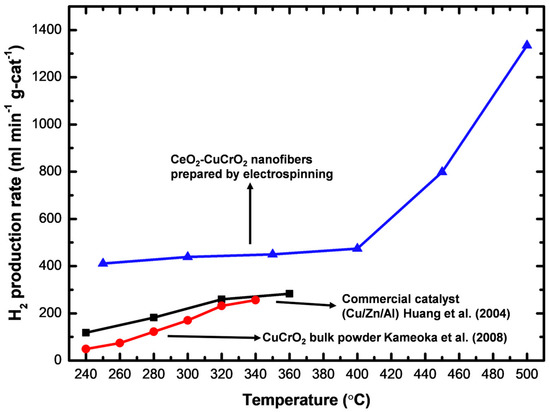
Figure 10.
Hydrogen production of electrospinning prepared CeO2-CuCrO2, compared with CuCrO2 (solid-state method) [24] and commercial Cu/Zn/Al catalysts [35].
4. Conclusions
In this study, the electrospun CeO2-CuCrO2 nanofiber catalyst was effectively created and used for steam reforming of methanol (SRM). The prepared nanofiber catalyst was evaluated by the field emission scanning electron microscope, transmission electron microscope, X-ray diffractometer energy-dispersive X-ray spectroscopy, thermogravimetric analyzer (STA), and Brunauer-Emmett-Teller analysis. The specific surface area of the CeO2-CuCrO2 nanofibers is 15.06 m2/g. The best hydrogen production rate of the CeO2-CuCrO2 nanofibers, 1335.16 mL min−1 g-cat−1, was achieved at a flow rate of 30 sccm and reaction temperature of 773 K. Furthermore, the optimization of reduction conditions and catalyst stability were studied. According to the findings, the increased hydrogen production rate can be ascribed to the stronger catalytic activity, larger surface area, lower reactor temperature, and higher methanol flow rate of the CeO2-CuCrO2 nanofiber catalyst. According to the H2 production performance, the CeO2-CuCrO2 nanofibers can be employed as a better catalyst for commercial H2 production and are suited for fuel cell vehicles without high-temperature activation.
Author Contributions
Conceptualization, Investigation, writing—original draft preparation, K.-C.H.; writing—review and editing, Investigation, Software, C.-L.Y.; writing—review and editing, H.-J.L.; writing—review and editing, S.S.; Validation, P.-C.C.; Methodology, C.-C.L.; Validation, Supervision, Methodology, T.-W.C.; writing—review and editing, L.F.; writing—review and editing, K.N. and Y.-H.L. All authors have read and agreed to the published version of the manuscript.
Funding
This work was supported by the Ministry of Science and Technology of Taiwan (MOST 108-2221-E-027-056, MOST 109-2221-E-027-068, MOST 109-2221-E-027-059, MOST 110-2221-E-027-041, and MOST 109-2113-M-027-001-MY3). This work was supported by the National Science and Technology Council of Taiwan (NSTC 111-2221-E-027-104). The authors appreciate the Precision Research and Analysis Centre of the National Taipei University of Technology (NTUT) for providing the measurement facilities.
Institutional Review Board Statement
Not applicable.
Informed Consent Statement
Not applicable.
Data Availability Statement
Not applicable.
Acknowledgments
This work was supported by the Ministry of Science and Technology of Taiwan (MOST 108-2221-E-027-056, MOST 109-2221-E-027-059, MOST 109-2221-E-027-068, and MOST 109-2113-M-027-001-MY3) and the National Science and Technology Council of Taiwan (NSTC 111-2221-E-027-104). The thanks to Precision Research and Analysis Centre of the National Taipei University of Technology (NTUT) for the measurement support.
Conflicts of Interest
The authors declare no conflict of interest.
References
- Yu, C.L.; Sakthinathan, S.; Hwang, B.Y.; Lin, S.Y.; Chiu, T.W.; Yu, B.S.; Fan, Y.J.; Chuang, C. CuFeO2–CeO2 Nanopowder Catalyst Prepared by Self-Combustion Glycine Nitrate Process and Applied for Hydrogen Production from Methanol Steam Reforming. Int. J. Hydrogen Energy 2020, 45, 15752–15762. [Google Scholar] [CrossRef]
- Huang, R.J.; Sakthinathan, S.; Chiu, T.W.; Dong, C. Hydrothermal Synthesis of High Surface Area CuCrO2 for H2 production by Methanol Steam Reforming. RSC Adv. 2021, 11, 12607–12613. [Google Scholar] [CrossRef] [PubMed]
- Yu, C.L.; Sakthinathan, S.; Chen, S.Y.; Yu, B.S.; Chiu, T.W.; Dong, C. Hydrogen Generation by Methanol Steam Reforming Process by Delafossite-Type CuYO2 Nanopowder Catalyst. Microporous Mesoporous Mater. 2021, 324, 111305. [Google Scholar] [CrossRef]
- Chiu, T.W.; Hong, R.T.; Yu, B.S.; Huang, Y.H.; Kameoka, S.; Tsai, A.P. Improving Steam-Reforming Performance by Nanopowdering CuCrO2. Int. J. Hydrogen Energy 2014, 39, 14222–14226. [Google Scholar] [CrossRef]
- Abbasi, M.; Farniaei, M.; Rahimpour, M.R.; Shariati, A. Enhancement of Hydrogen Production and Carbon Dioxide Capturing in a Novel Methane Steam Reformer Coupled with Chemical Looping Combustion and Assisted by Hydrogen Perm-Selective Membranes. Energy Fuels 2013, 27, 5359–5372. [Google Scholar] [CrossRef]
- Wiese, W.; Emonts, B.; Peters, R. Methanol Steam Reforming in a Fuel Cell Drive System. J. Power Sources 1999, 84, 187–193. [Google Scholar] [CrossRef]
- Palo, D.R.; Dagle, R.A.; Holladay, J.D. Methanol Steam Reforming for Hydrogen Production. Chem. Rev. 2007, 107, 3992–4021. [Google Scholar] [CrossRef]
- Itoh, N.; Kaneko, Y.; Igarashi, A. Efficient Hydrogen Production via Methanol Steam Reforming by Preventing Back-Permeation of Hydrogen in a Palladium Membrane Reactor. Ind. Eng. Chem. Res. 2002, 41, 4702–4706. [Google Scholar] [CrossRef]
- Pajaie, H.S. Hydrogen Production from Methanol Steam Reforming over Cu/ZnO/Al2O3/CeO2/ZrO2 Nanocatalyst in an Adiabatic Fixed-Bed Reactor. Iran. J. Energy Environ. 2012, 3, 307–313. [Google Scholar] [CrossRef]
- Papavasiliou, J.; Avgouropoulos, G.; Ioannides, T. Production of Hydrogen via Combined Steam Reforming of Methanol over CuO-CeO2 Catalysts. Catal. Commun. 2004, 5, 231–235. [Google Scholar] [CrossRef]
- Chen, W.H.; Lin, B.J. Effect of Microwave Double Absorption on Hydrogen Generation from Methanol Steam Reforming. Int. J. Hydrogen Energy 2010, 35, 1987–1997. [Google Scholar] [CrossRef]
- Agrell, J.; Birgersson, H.; Boutonnet, M. Steam Reforming of Methanol over a Cu/ZnO/Al2O3 Catalyst: A Kinetic Analysis and Strategies for Suppression of CO Formation. J. Power Sources 2002, 106, 249–257. [Google Scholar] [CrossRef]
- Kameoka, S.; Tanabe, T.; Tsai, A.P. Self-Assembled Porous Nano-Composite with High Catalytic Performance by Reduction of Tetragonal Spinel CuFe2O4. Appl. Catal. A Gen. 2010, 375, 163–171. [Google Scholar] [CrossRef]
- Christopher, J.; Swamy, C.S. Catalytic Activity and XPS Investigation of Dalofossite Oxides, CuMO2 (M=Al, Cr or Fe). J. Mater. Sci. 1992, 27, 1353–1356. [Google Scholar] [CrossRef]
- Saadi, S.; Bouguelia, A.; Trari, M. Photocatalytic Hydrogen Evolution over CuCrO2. Sol. Energy 2006, 80, 272–280. [Google Scholar] [CrossRef]
- Shen, J.P.; Song, C. Influence of Preparation Method on Performance of Cu/Zn-Based Catalysts for Low-Temperature Steam Reforming and Oxidative Steam Reforming of Methanol for H2 Production for Fuel Cells. Catal. Today 2002, 77, 89–98. [Google Scholar] [CrossRef]
- Abrokwah, R.Y.; Deshmane, V.G.; Owen, S.L.; Kuila, D. Cu-Ni Nanocatalysts in Mesoporous MCM-41 and TiO2 to Produce Hydrogen for Fuel Cells via Steam Reforming Reactions. Adv. Mater. Res. 2015, 1096, 161–168. [Google Scholar] [CrossRef]
- Navarro, R.M.; Peña, M.A.; Fierro, J.L.G. Production of Hydrogen by Partial Oxidation of Methanol over a Cu/ZnO/Al2O3 Catalyst: Influence of the Initial State of the Catalyst on the Start-up Behaviour of the Reformer. J. Catal. 2002, 212, 112–118. [Google Scholar] [CrossRef]
- Lindström, B.; Pettersson, L.J.; Menon, G. Activity and Characterization of Cu/Zn, Cu/Cr and Cu/Zr on γ-Alumina for Methanol Reforming for Fuel Cell Vehicles. Appl. Catal. A Gen. 2002, 234, 111–125. [Google Scholar] [CrossRef]
- Shokrani, R.; Haghighi, M.; Ajamein, H.; Abdollahifar, M. Hybrid Sonochemic Urea-Nitrate Combustion Preparation of CuO/ZnO/Al2O3 Nanocatalyst Used in Fuel Cell-Grade Hydrogen Production from Methanol: Effect of Sonication and Fuel/Nitrate Ratio. Part. Sci. Technol. 2018, 36, 217–225. [Google Scholar] [CrossRef]
- Basile, A.; Parmaliana, A.; Tosti, S.; Iulianelli, A.; Gallucci, F.; Espro, C.; Spooren, J. Hydrogen Production by Methanol Steam Reforming Carried out in Membrane Reactor on Cu/Zn/Mg-Based Catalyst. Catal. Today 2008, 137, 17–22. [Google Scholar] [CrossRef]
- Huang, Y.H.; Wang, S.F.; Tsai, A.P.; Kameoka, S. Reduction Behaviors and Catalytic Properties for Methanol Steam Reforming of Cu-based Spinel Compounds CuX2O4 (X=Fe, Mn, Al, La). Ceram. Int. 2014, 40, 4541–4551. [Google Scholar] [CrossRef]
- Bichon, P.; Asheim, M.; Sperle, A.J.T.; Fathi, M.; Holmen, A.; Blekkan, E.A. Hydrogen from Methanol Steam-Reforming over Cu-based Catalysts with and without Pd Promotion. Int. J. Hydrog. Energy 2007, 32, 1799–1805. [Google Scholar] [CrossRef]
- Kameoka, S.; Okada, M.; Tsai, A.P. Preparation of a Novel Copper Catalyst in Terms of the Immiscible Interaction between Copper and Chromium. Catal. Lett. 2008, 120, 252–256. [Google Scholar] [CrossRef]
- Sato, S.; Takahashi, R.; Sodesawa, T.; Yuma, K.I.; Obata, Y. Distinction between Surface and Bulk Oxidation of Cu through N2O Decomposition. J. Catal. 2000, 196, 195–199. [Google Scholar] [CrossRef]
- Hwang, B.Y.; Sakthinathan, S.; Chiu, T.W. Production of Hydrogen from Steam Reforming of Methanol Carried out by Self-Combusted CuCr1-xFexO2 (x=0–1) Nanopowders Catalyst. Int. J. Hydrog. Energy 2019, 44, 2848–2856. [Google Scholar] [CrossRef]
- Amrute, A.P.; Larrazábal, G.O.; Mondelli, C.; Pérez-Ramírez, J. CuCrO2 delafossite: A Stable Copper Catalyst for Chlorine Production. Angew. Chem. Int. Ed. 2013, 52, 9772–9775. [Google Scholar] [CrossRef]
- Ketir, W.; Bouguelia, A.; Trari, M. NO3- Removal with a New Delafossite CuCrO2 Photocatalyst. Desalination 2009, 244, 144–152. [Google Scholar] [CrossRef]
- Singh, S. Cerium Oxide Based Nanozymes: Redox Phenomenon at Biointerfaces. Biointerphases 2016, 11, 04B202. [Google Scholar] [CrossRef]
- Hornés, A.; Hungría, A.B.; Bera, P.; López Cámara, A.; Fernández-García, M.; Martínez-Arias, A.; Barrio, L.; Estrella, M.; Zhou, G.; Fonseca, J.J.; et al. Inverse CeO2/CuO Catalyst as an Alternative to Classical Direct Configurations for Preferential Oxidation of CO in Hydrogen-Rich Stream. J. Am. Chem. Soc. 2010, 132, 34–35. [Google Scholar] [CrossRef]
- Li, Y.; Cai, Y.; Xing, X.; Chen, N.; Deng, D.; Wang, Y. Catalytic Activity for CO Oxidation of Cu-CeO2 Composite Nanoparticles Synthesized by a Hydrothermal Method. Anal. Methods 2015, 7, 3238–3245. [Google Scholar] [CrossRef]
- Tucker, N.; Stanger, J.J.; Staiger, M.P.; Razzaq, H.; Hofman, K. The History of the Science and Technology of Electrospinning from 1600 to 1995. J. Eng. Fibers Fabr. 2012, 7, 63–73. [Google Scholar] [CrossRef]
- Thavasi, V.; Singh, G.; Ramakrishna, S. Electrospun Nanofibers in Energy and Environmental Applications. Energy Environ. Sci. 2008, 1, 205–221. [Google Scholar] [CrossRef]
- Chao, T.C.; Chiu, T.W.; Fu, Y. Fabrication and Characteristic of Delafossite-Type CuFeO2 Nanofibers by Electrospinning Method. Ceram. Int. 2018, 44, S80–S83. [Google Scholar] [CrossRef]
- Huang, X.; Ma, L.; Wainwright, M.S. The influence of Cr, Zn and Co additives on the performance of skeletal copper catalysts for methanol synthesis and related reactions. Appl. Catal. A Gen. 2004, 257, 235–243. [Google Scholar] [CrossRef]


Publisher’s Note: MDPI stays neutral with regard to jurisdictional claims in published maps and institutional affiliations. |
© 2022 by the authors. Licensee MDPI, Basel, Switzerland. This article is an open access article distributed under the terms and conditions of the Creative Commons Attribution (CC BY) license (https://creativecommons.org/licenses/by/4.0/).