
Gas Diffusion Layer for Proton Exchange Membrane Fuel Cells: A Review


Abstract
:
1. Introduction
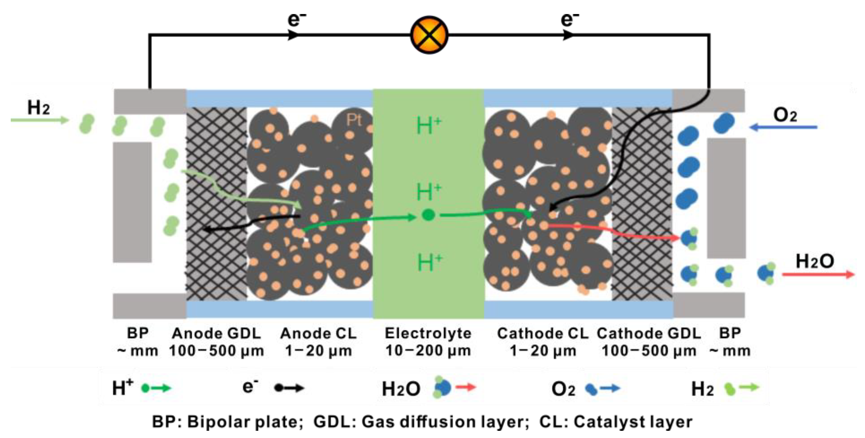
2. Brief Introduction of PEMFCs
3. General Requirements for GDL
- (1)
- High gas permeability. The pore structure of GDL impacts the transport properties greatly, since the gas involved in the reaction needs to pass through the GDL to reach the CL to participate in the electrochemical reaction. The electrolyte membrane also needs to be hydrated by being subjected to the wet atmosphere to maintain high proton conductivity. Moreover, water generated from the reaction in PEMFCs needs adequate routes to be drained without flooding the CL and GDL [24,25,26]. Zhou et al. [27] found that the ability of mass transfer was enhanced by reducing the length of the channel for gas flow and increasing the porosity of the anode GDL (A-GDL). Sim et al. [28] reported a new approach to increasing the porosity and pore size of GDL by changing the gasket thickness, resulting in a positive effect on the drainage capacity.
- (2)
- High electrical conductivity. The GDL provides the electrical connection between the CL and the BP. It delivers electrons from the BP to cathode CL, and collects electrons from anode CL to the BP. Therefore, high electrical conductivity is required for a GDL to decrease its ohmic loss and contact resistance with the adjacent BP and CL [29].
- (3)
- High thermal conductivity. During the operation of PEMFCs, heat is generated and tends to accumulate locally. If the extra heat is not removed quickly from the system, the increasing temperature shortens the longevity of PEMFCs. Thereby, the GDL must have high thermal conductivity to conduct the extra heat quickly to the BP to ensure a safe system temperature. Botelho et al. [30] applied a resistance network theory to estimate effective thermal contact resistance between the carbon fibers used for composing the GDL. They found that the change in fiber roughness led to a large change in the effective thermal contact resistance, implying a feasible approach to regulate the thermal conduction of the GDL by controlling the morphology of the carbon fibers.
- (4)
- Good mechanical strength. The GDL must be robust enough to offer mechanical support to the MEA and protect the CL and the electrolyte membrane. Furthermore, a mechanically stable porous structure is vital to construct and maintain channels for gas diffusion and drainage. Csoklich et al. [31] suggested that it was efficient to improve the performance of the GDL by optimizing the structure rather than improving the thermal conduction in order to achieve excellent performance at high current density.
- (5)
- Good chemical/thermal stability and corrosion resistance. To minimize the degradation rate during long-term operation, the GDL is required to be stable both chemically and thermally, as well as corrosion-resistant in both oxidizing and reducing atmospheres in the chambers of cathode and anode, respectively.
- (6)
- Facilitation of water removal. To facilitate the drainage at the cathode, the GDL at the cathode is usually processed to be hydrophobic. Moreover, other factors (such as the geometric parameters of the carbon fibers composing the GDL) also effect the hydrophobicity. Wang et al. [32] found that the speed of water discharge was enhanced by increasing the diameter of the carbon fibers in the GDL.
- (7)
- Low cost. The volumetric ratio of the GDL in PEMFCs is not low (larger than that of the CL and electrolyte), so it is necessary to choose proper materials with both a low cost and a high performance.
4. Macroporous Substrate
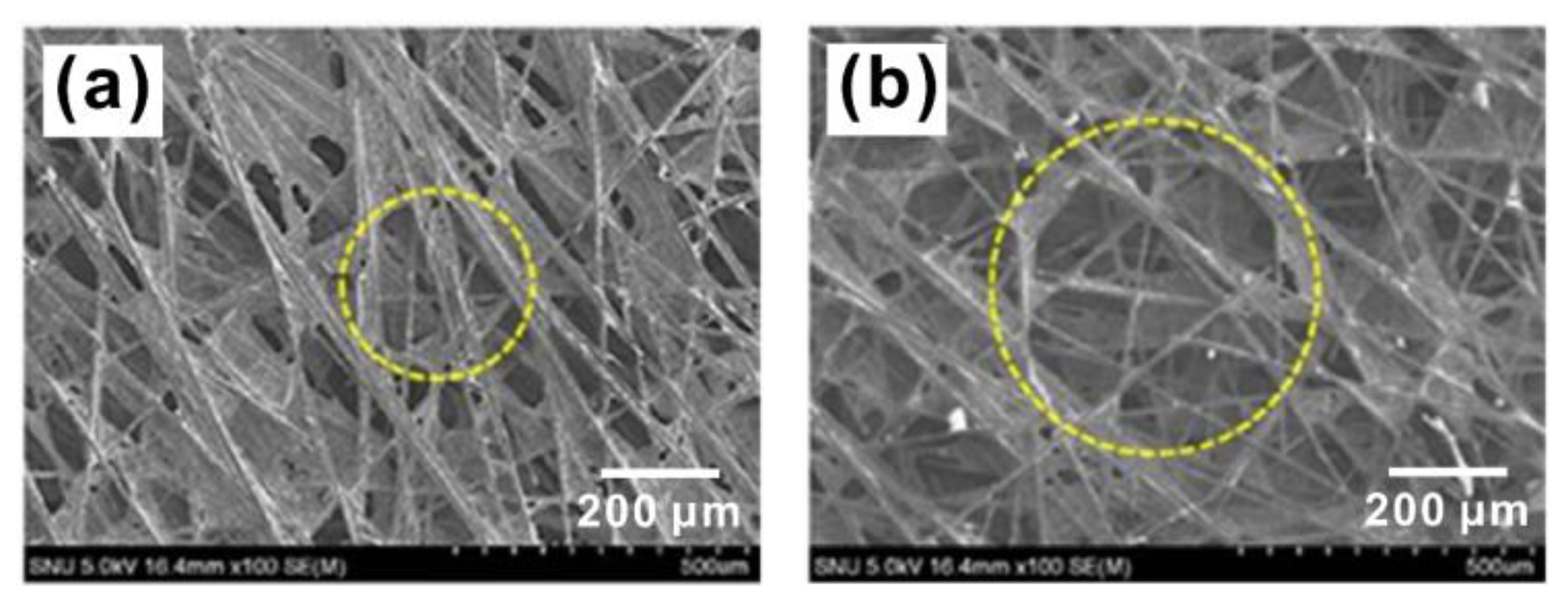
4.1. Carbon Fiber Paper
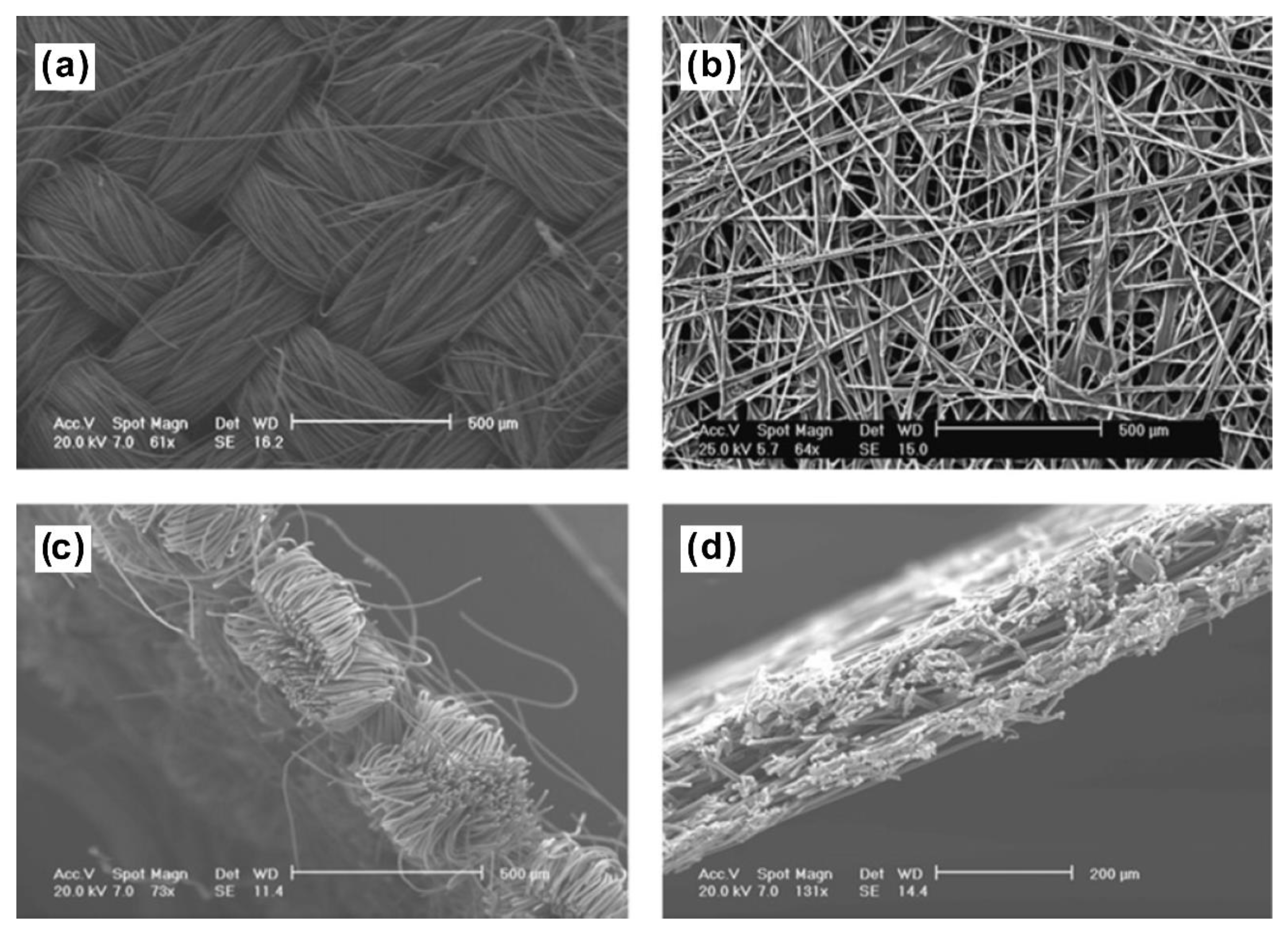
4.2. Carbon Fiber Cloth
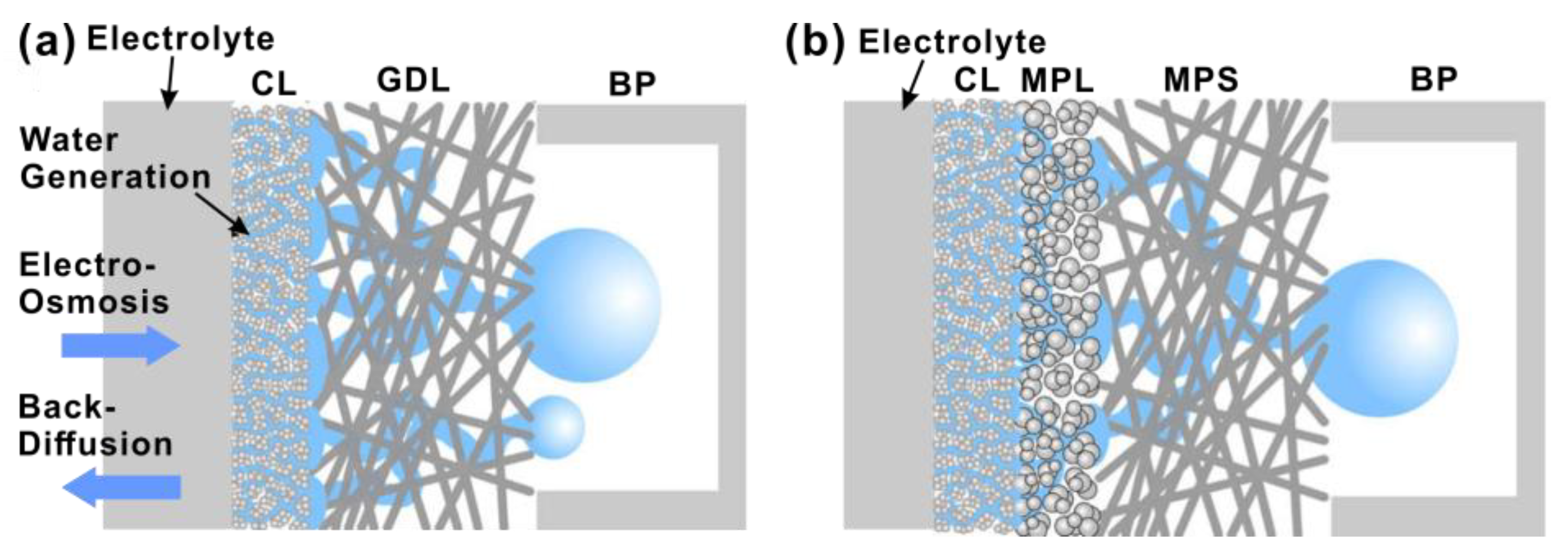
5. Microporous Layer
5.1. MPL Fabrication Process
5.2. Hydrophobization
6. Structural Parameters for GDL
6.1. Pore Structure
6.2. Thickness
7. Other Attempts to Improve Performance of GDL
8. Concluding Remarks
Author Contributions
Funding
Institutional Review Board Statement
Informed Consent Statement
Data Availability Statement
Conflicts of Interest
Abbreviations
| AFCs | Alkaline fuel cells | MEA | Membrane electrode assembly |
| ALD | Atomic layer deposition | MPL | Microporous layer |
| BPs | Bipolar plates | MPS | Microporous substrate |
| BVF | Volume fractions of binders | NMP | N-methyl-2-pyrrolidone |
| CF | Carbon fiber | ORR | Oxygen reduction reaction |
| CL | Anode catalyst layer | PAFCs | Phosphoric acid fuel cells |
| CNF | Carbon nanofiber | PAN | Polyacrylonitrile |
| CNTs | carbon nanotubes | PDMS | Polydimethylsiloxane |
| CR | Compression ratios | PECVD | Plasma enhanced chemical vapor deposition |
| CVD | Chemical vapor deposition | PEMFCs | Proton exchange membrane fuel cells |
| DMF | N, N-dimethylformamide | PFPE | Perfluoropolyether |
| FCVs | Fuel cell vehicles | PI | Polyimide |
| FEP | Fluorinated ethylene | PTFE | Poly tetra fluoroethylene |
| FWCNT | Few-walled carbon nanotube | PVDF | Polyvinylidene fluoride |
| GDL | Gas diffusion layer | PVP | Polyvinyl pyrrolidone |
| HOR | Hydrogen oxidation reaction | rGO | Reduced graphene oxide |
| i-FF-GDL | Integrated flow field-gas diffusion layer | RH | Relative humidity |
| MCFCs | Molten carbonate fuel cells | SOFCs | Solid oxide fuel cells |
| MEA | Membrane electrode assemblies |
References
- Bacon, F.T. Fuel Cells, Past, Present and Future. Electrochim. Acta 1969, 14, 569. [Google Scholar] [CrossRef]
- Lanzini, A.; Madi, H.; Chiodo, V.; Papurello, D.; Maisano, S.; Santarelli, M.; Van Herle, J. Dealing with fuel contaminants in biogas-fed solid oxide fuel cell (SOFC) and molten carbonate fuel cell (MCFC) plants: Degradation of catalytic and electro-catalytic active surfaces and related gas purification methods. Prog. Energy Combust. Sci. 2017, 61, 150–188. [Google Scholar] [CrossRef] [Green Version]
- Gür, T.M. Comprehensive review of methane conversion in solid oxide fuel cells: Prospects for efficient electricity generation from natural gas. Prog. Energy Combust. Sci. 2016, 54, 1–64. [Google Scholar]
- André, J.; Antoni, L.; Petit, J.-P.; De Vito, E.; Montani, A. Electrical contact resistance between stainless steel bipolar plate and carbon felt in PEFC: A comprehensive study. Int. J. Hydrogen Energy 2009, 34, 3125–3133. [Google Scholar] [CrossRef]
- Krishnan, S.; Armstrong, F.A. Order-of-magnitude enhancement of an enzymatic hydrogen-air fuel cell based on pyrenyl carbon nanostructures. Chem. Sci. 2012, 3, 1015–1023. [Google Scholar] [CrossRef]
- Park, S.D.; Vohs, J.M.; Gorte, R.J. Direct oxidation of hydrocarbons in a solid-oxide fuel cell. Nature 2000, 404, 265–267. [Google Scholar] [CrossRef]
- Kreuer, K.D. On the development of proton conducting polymer membranes for hydrogen and methanol fuel cells. J. Membr. Sci. 2001, 185, 29–39. [Google Scholar] [CrossRef]
- Liu, H.; Song, C.; Zhang, L.; Zhang, J.; Wang, H.; Wilkinson, D.P. A review of anode catalysis in the direct methanol fuel cell. J. Power Sources 2006, 155, 95–110. [Google Scholar] [CrossRef]
- Antolini, E. Catalysts for direct ethanol fuel cells. J. Power Sources 2007, 170, 1–12. [Google Scholar] [CrossRef]
- Wang, Y.; Chen, K.S.; Mishler, J.; Cho, S.C.; Adroher, X.C. A review of polymer electrolyte membrane fuel cells: Technology, applications, and needs on fundamental research. Appl. Energy 2011, 88, 981–1007. [Google Scholar] [CrossRef] [Green Version]
- Hogarth, W.H.J.; Diniz da Costa, J.C.; Lu, G.Q. Solid acid membranes for high temperature (¿140° C) proton exchange membrane fuel cells. J. Power Sources 2005, 142, 223–237. [Google Scholar] [CrossRef]
- Morgan, J.M.; Datta, R. Understanding the gas diffusion layer in proton exchange membrane fuel cells. I. How its structural characteristics affect diffusion and performance. J. Power Sources 2014, 251, 269–278. [Google Scholar] [CrossRef]
- Zamel, N.; Li, X. Transient analysis of carbon monoxide poisoning and oxygen bleeding in a PEM fuel cell anode catalyst layer. Int. J. Hydrogen Energy 2008, 33, 1335–1344. [Google Scholar] [CrossRef]
- Chiu, L.Y.; Diong, B.; Gemmen, R.S. An Improved Small-Signal Model of the Dynamic Behavior of PEM Fuel Cells. IEEE Trans. Ind. Appl. 2004, 40, 970–977. [Google Scholar] [CrossRef]
- Mehta, V.; Cooper, J.S. Review and analysis of PEM fuel cell design and manufacturing. J. Power Sources 2003, 114, 32–53. [Google Scholar] [CrossRef]
- Manso, A.P.; Marzo, F.F.; Barranco, J.; Garikano, X.; Garmendia Mujika, M. Influence of geometric parameters of the flow fields on the performance of a PEM fuel cell. A review. Int. J. Hydrogen Energy 2012, 37, 15256–15287. [Google Scholar] [CrossRef]
- Ge, J.; Higier, A.; Liu, H. Effect of gas diffusion layer compression on PEM fuel cell performance. J. Power Sources 2006, 159, 922–927. [Google Scholar] [CrossRef]
- Acres, G.J.K.; Frost, J.C.; Hards, G.A.; Potter, R.J.; Ralph, T.R.; Thompsett, D.; Burstein, G.T.; Hutchings, G.J. Electrocatalysts for fuel cells. Catal. Today 1997, 38, 393–400. [Google Scholar] [CrossRef]
- Ross, P.N.; Kinoshita, K.; Scarpellino, A.J.; Stonehart, P. Electrocatalysis on Binary-Alloys.1. Oxidation of Molecular-Hydrogen on Supported Pt-Rh Alloys. J. Electroanal. Chem. 1975, 59, 177–189. [Google Scholar] [CrossRef]
- Peighambardoust, S.J.; Rowshanzamir, S.; Amjadi, M. Review of the proton exchange membranes for fuel cell applications. Int. J. Hydrogen Energy 2010, 35, 9349–9384. [Google Scholar] [CrossRef]
- Gurau, V.; Zawodzinski, T.A.; Mann, J.A. Two-phase transport in PEM fuel cell cathodes. J. Fuel Cell Sci. Technol. 2008, 5, 021009. [Google Scholar] [CrossRef]
- Masuda, H.; Ito, K.; Oshima, T.; Sasaki, K. Comparison between numerical simulation and visualization experiment on water behavior in single straight flow channel polymer electrolyte fuel cells. J. Power Sources 2008, 177, 303–313. [Google Scholar] [CrossRef]
- Passalacqua, E.; Squadrito, G.; Lufrano, F.; Patti, A.; Giorgi, L. Effects of the diffusion layer characteristics on the performance of polymer electrolyte fuel cell electrodes. J. Appl. Electrochem. 2001, 31, 449–454. [Google Scholar] [CrossRef]
- Zenyuk, I.V.; Parkinson, D.Y.; Hwang, G.; Weber, A.Z. Probing water distribution in compressed fuel-cell gas-diffusion layers using X-ray computed tomography. Electrochem. Commun. 2015, 53, 24–28. [Google Scholar] [CrossRef] [Green Version]
- Park, J.; Oh, H.; Ha, T.; Lee, Y.I.; Min, K. A review of the gas diffusion layer in proton exchange membrane fuel cells: Durability and degradation. Appl. Energy 2015, 155, 866–880. [Google Scholar] [CrossRef]
- Deevanhxay, P.; Sasabe, T.; Tsushima, S.; Hirai, S. Observation of dynamic liquid water transport in the microporous layer and gas diffusion layer of an operating PEM fuel cell by high-resolution soft X-ray radiography. J. Power Sources 2013, 230, 38–43. [Google Scholar] [CrossRef]
- Zhou, H.R.; Chen, B.; Meng, K.; Luo, M.J.; Li, P.; Tu, Z.K. Combination effect of flow channel configuration and anode GDL porosity on mass transfer and performance of PEM water electrolyzers. Sustain. Energy Fuels 2022, 6, 3944–3960. [Google Scholar] [CrossRef]
- Sim, J.; Kang, M.; Min, K. Effects of porosity gradient and average pore size in the in-plane direction and disposition of perforations in the gas diffusion layer on the performance of proton exchange membrane fuel cells. J. Power Sources 2022, 544, 231912. [Google Scholar] [CrossRef]
- Owejan, J.P.; Trabold, T.A.; Mench, M.M. Oxygen transport resistance correlated to liquid water saturation in the gas diffusion layer of PEM fuel cells. Int. J. Heat Mass Transf. 2014, 71, 585–592. [Google Scholar] [CrossRef]
- Botelho, S.J.; Bazylak, A. The impact of fibre surface morphology on the effective thermal conductivity of a polymer electrolyte membrane fuel cell gas diffusion layer. J. Power Sources 2014, 269, 385–395. [Google Scholar] [CrossRef]
- Csoklich, C.; Sabharwal, M.; Schmidt, T.J.; Büchi, F.N. Does the thermal conductivity of gas diffusion layer matter in polymer electrolyte fuel cells? J. Power Sources 2022, 540, 231539. [Google Scholar] [CrossRef]
- Wang, X.L.; Qu, Z.G.; Lai, T.; Ren, G.F.; Wang, W.K. Enhancing water transport performance of gas diffusion layers through coupling manipulation of pore structure and hydrophobicity. J. Power Sources 2022, 525, 231121. [Google Scholar] [CrossRef]
- Joo, D.; Jin, S.M.; Jang, J.H.; Park, S. Development of a Self-supporting Microporous Layer on a Metal Mesh for Carbon Backing-free Cathodes in Proton Exchange Membrane Fuel Cells. Fuel Cells 2018, 18, 57–62. [Google Scholar] [CrossRef]
- Taherian, R.; Matboo Ghorbani, M.; Kiahosseini, S.R. A new method for optimal fabrication of carbon composite paper as gas diffusion layer used in proton exchange membrane of fuel cells. J. Electroanal. Chem. 2018, 815, 90–97. [Google Scholar] [CrossRef]
- Simaafrookhteh, S.; Taherian, R.; Shakeri, M. Stochastic Microstructure Reconstruction of a Binder/Carbon Fiber/Expanded Graphite Carbon Fiber Paper for PEMFCs Applications: Mass Transport and Conductivity Properties. J. Electrochem. Soc. 2019, 166, F3287–F3299. [Google Scholar] [CrossRef]
- Chen, W.; Jiang, F. Impact of PTFE content and distribution on liquid–gas flow in PEMFC carbon paper gas distribution layer: 3D lattice Boltzmann simulations. Int. J. Hydrogen Energy 2016, 41, 8550–8562. [Google Scholar] [CrossRef]
- Dicks, A.L. The role of carbon in fuel cells. J. Power Sources 2006, 156, 128–141. [Google Scholar] [CrossRef]
- Cindrella, L.; Kannan, A.M.; Lin, J.F.; Saminathan, K.; Ho, Y.; Lin, C.W.; Wertz, J. Gas diffusion layer for proton exchange membrane fuel cells-A review. J. Power Sources 2009, 194, 146–160. [Google Scholar] [CrossRef]
- Wilde, P.M.; Mändle, M.; Murata, M.; Berg, N. Structural and Physical Properties of GDL and GDL/BPP Combinations and their Influence on PEMFC Performance. Fuel Cells 2004, 4, 180–184. [Google Scholar] [CrossRef]
- Kitago, T.; Yoshida, T. Paper Made from Carbon Fibers. U.S. Patent 2432706, 6 February 1975. [Google Scholar]
- Park, J.; Oh, H.; Lee, Y.I.; Min, K.; Lee, E.; Jyoung, J.-Y. Effect of the pore size variation in the substrate of the gas diffusion layer on water management and fuel cell performance. Appl. Energy 2016, 171, 200–212. [Google Scholar] [CrossRef]
- Jayakumar, A.; Sethu, S.P.; Ramos, M.; Robertson, J.; Al-Jumaily, A. A technical review on gas diffusion, mechanism and medium of PEM fuel cell. Ionics 2014, 21, 1–18. [Google Scholar] [CrossRef]
- Radhakrishnan, V.; Haridoss, P. Differences in structure and property of carbon paper and carbon cloth diffusion media and their impact on proton exchange membrane fuel cell flow field design. Mater. Des. 2011, 32, 861–868. [Google Scholar] [CrossRef]
- Hung, C.-J.; Liu, C.-H.; Wang, C.-H.; Chen, W.-H.; Shen, C.-W.; Liang, H.-C.; Ko, T.-H. Effect of conductive carbon material content and structure in carbon fiber paper made from carbon felt on the performance of a proton exchange membrane fuel cell. Renew. Energy 2015, 78, 364–373. [Google Scholar] [CrossRef]
- Yang, H.; Tu, H.C.; Chiang, I.L. Carbon cloth based on PAN carbon fiber practicability for PEMFC applications. Int. J. Hydrogen Energy 2010, 35, 2791–2795. [Google Scholar] [CrossRef]
- El-kharouf, A.; Mason, T.J.; Brett, D.J.L.; Pollet, B.G. Ex-situ characterisation of gas diffusion layers for proton exchange membrane fuel cells. J. Power Sources 2012, 218, 393–404. [Google Scholar] [CrossRef] [Green Version]
- Chun, J.H.; Park, K.T.; Jo, D.H.; Lee, J.Y.; Kim, S.G.; Lee, E.S.; Jyoung, J.-Y.; Kim, S.H. Determination of the pore size distribution of micro porous layer in PEMFC using pore forming agents under various drying conditions. Int. J. Hydrogen Energy 2010, 35, 11148–11153. [Google Scholar] [CrossRef]
- Wu, R.; Zhu, X.; Liao, Q.; Wang, H.; Ding, Y.-d.; Li, J.; Ye, D.-d. A pore network study on the role of micro-porous layer in control of liquid water distribution in gas diffusion layer. Int. J. Hydrogen Energy 2010, 35, 7588–7593. [Google Scholar] [CrossRef]
- Weber, A.Z.; Newman, J. Effects of microporous layers in polymer electrolyte fuel cells. J. Electrochem. Soc. 2005, 152, A677–A688. [Google Scholar] [CrossRef]
- O’Hayre, R.; Cha, S.W.; Colella, W.; Prinz, F.B. PEMFC and SOFC Materials. In Fuel Cell Fundamentals; John and Wiley and Sons: Hoboken, NJ, USA, 2016; pp. 303–346, Chapter 9. [Google Scholar]
- Nam, J.H.; Lee, K.-J.; Hwang, G.-S.; Kim, C.-J.; Kaviany, M. Microporous layer for water morphology control in PEMFC. Int. J. Heat Mass Transf. 2009, 52, 2779–2791. [Google Scholar] [CrossRef]
- Jung, G.-B.; Tzeng, W.-J.; Jao, T.-C.; Liu, Y.-H.; Yeh, C.-C. Investigation of porous carbon and carbon nanotube layer for proton exchange membrane fuel cells. Appl. Energy 2013, 101, 457–464. [Google Scholar] [CrossRef]
- Chen, H.-H.; Chang, M.-H. Effect of cathode microporous layer composition on proton exchange membrane fuel cell performance under different air inlet relative humidity. J. Power Sources 2013, 232, 306–309. [Google Scholar] [CrossRef]
- Li, B.; Xie, M.; Ji, H.; Chu, T.; Yang, D.; Ming, P.; Zhang, C. Optimization of cathode microporous layer materials for proton exchange membrane fuel cell. Int. J. Hydrogen Energy 2021, 46, 14674–14686. [Google Scholar] [CrossRef]
- Hendricks, F.; Chamier, J.; Tanaka, S. Membrane electrode assembly performance of a standalone microporous layer on a metallic gas diffusion layer. J. Power Sources 2020, 464, 228222. [Google Scholar] [CrossRef]
- Schweiss, R.; Steeb, M.; Wilde, P.M.; Schubert, T. Enhancement of proton exchange membrane fuel cell performance by doping microporous layers of gas diffusion layers with multiwall carbon nanotubes. J. Power Sources 2012, 220, 79–83. [Google Scholar] [CrossRef]
- Kumar, R.J.F.; Radhakrishnan, V.; Haridoss, P. Enhanced mechanical and electrochemical durability of multistage PTFE treated gas diffusion layers for proton exchange membrane fuel cells. Int. J. Hydrogen Energy 2012, 37, 10830–10835. [Google Scholar] [CrossRef]
- Park, G.-G.; Sohn, Y.-J.; Yang, T.-H.; Yoon, Y.-G.; Lee, W.-Y.; Kim, C.-S. Effect of PTFE contents in the gas diffusion media on the performance of PEMFC. J. Power Sources 2004, 131, 182–187. [Google Scholar] [CrossRef]
- Xie, Z.; Chen, G.; Yu, X.; Hou, M.; Shao, Z.; Hong, S.; Mu, C. Carbon nanotubes grown in situ on carbon paper as a microporous layer for proton exchange membrane fuel cells. Int. J. Hydrogen Energy 2015, 40, 8958–8965. [Google Scholar] [CrossRef]
- Ozden, A.; Shahgaldi, S.; Zhao, J.; Li, X.; Hamdullahpur, F. Assessment of graphene as an alternative microporous layer material for proton exchange membrane fuel cells. Fuel 2018, 215, 726–734. [Google Scholar] [CrossRef]
- Li, T.; Zhou, K.; Lin, G. Study on preparation process and durability of gas diffusion layer of proton exchange membrane fuel cell. Ionics 2022, 28, 1387–1401. [Google Scholar] [CrossRef]
- Chen, W.H.; Ko, T.H.; Cheng, S.I.; Hung, C.J.; Liang, H.C.; Lin, J.H.; Liu, C.H. Effect of various micro-porous layer preparation methods on the performance of a proton exchange membrane fuel cell. Int. J. Nanotechnol. 2014, 11, 993–1005. [Google Scholar] [CrossRef]
- Stampino, P.G.; Cristiani, C.; Dotelli, G.; Omati, L.; Zampori, L.; Pelosato, R.; Guilizzoni, M. Effect of different substrates, inks composition and rheology on coating deposition of microporous layer (MPL) for PEM-FCs. Catal. Today 2009, 147, S30–S35. [Google Scholar] [CrossRef]
- Yan, W.-M.; Wu, D.-K.; Wang, X.-D.; Ong, A.-L.; Lee, D.-J.; Su, A. Optimal microporous layer for proton exchange membrane fuel cell. J. Power Sources 2010, 195, 5731–5734. [Google Scholar] [CrossRef]
- Kannan, A.M.; Kanagala, P.; Veedu, V. Development of carbon nanotubes based gas diffusion layers by in situ chemical vapor deposition process for proton exchange membrane fuel cells. J. Power Sources 2009, 192, 297–303. [Google Scholar] [CrossRef]
- Maldonado, S.; Stevenson, K.J. Direct preparation of carbon nanofiber electrodes via pyrolysis of iron(II) phthalocyanine: Electrocatalytic aspects for oxygen reduction. J. Phys. Chem. B 2004, 108, 11375–11383. [Google Scholar] [CrossRef]
- Zhigalina, V.G.; Zhigalina, O.M.; Ponomarev, I.I.; Skupov, K.M.; Razorenov, D.Y.; Ponomarev, I.I.; Kiselev, N.A.; Leitinger, G. Electron microscopy study of new composite materials based on electrospun carbon nanofibers. CrystEngComm 2017, 19, 3792–3800. [Google Scholar] [CrossRef]
- Duan, Q.; Wang, B.; Wang, J.; Wang, H.; Lu, Y. Fabrication of a carbon nanofiber sheet as a micro-porous layer for proton exchange membrane fuel cells. J. Power Sources 2010, 195, 8189–8193. [Google Scholar] [CrossRef]
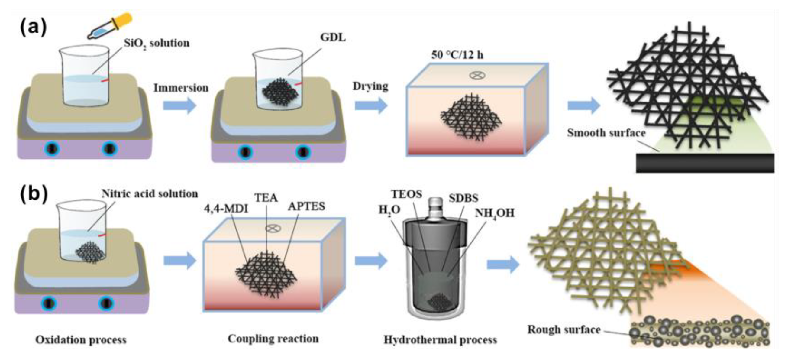
- Ozturk, A.; Yurtcan, A.B. Investigation of synergetic effect of PDMS polymer hydrophobicity and polystyrene-silica particles roughness in the content of microporous layer on water management in PEM fuel cell. Appl. Surf. Sci. 2020, 511, 145415. [Google Scholar] [CrossRef]
- Öztürk, A.; Fıçıcılar, B.; Eroğlu, İ.; Bayrakçeken Yurtcan, A. Facilitation of water management in low Pt loaded PEM fuel cell by creating hydrophobic microporous layer with PTFE, FEP and PDMS polymers: Effect of polymer and carbon amounts. Int. J. Hydrogen Energy 2017, 42, 21226–21249. [Google Scholar] [CrossRef]
- Gola, M.; Sansotera, M.; Navarrini, W.; Bianchi, C.L.; Gallo Stampino, P.; Latorrata, S.; Dotelli, G. Perfluoropolyether-functionalized gas diffusion layers for proton exchange membrane fuel cells. J. Power Sources 2014, 258, 351–355. [Google Scholar] [CrossRef]
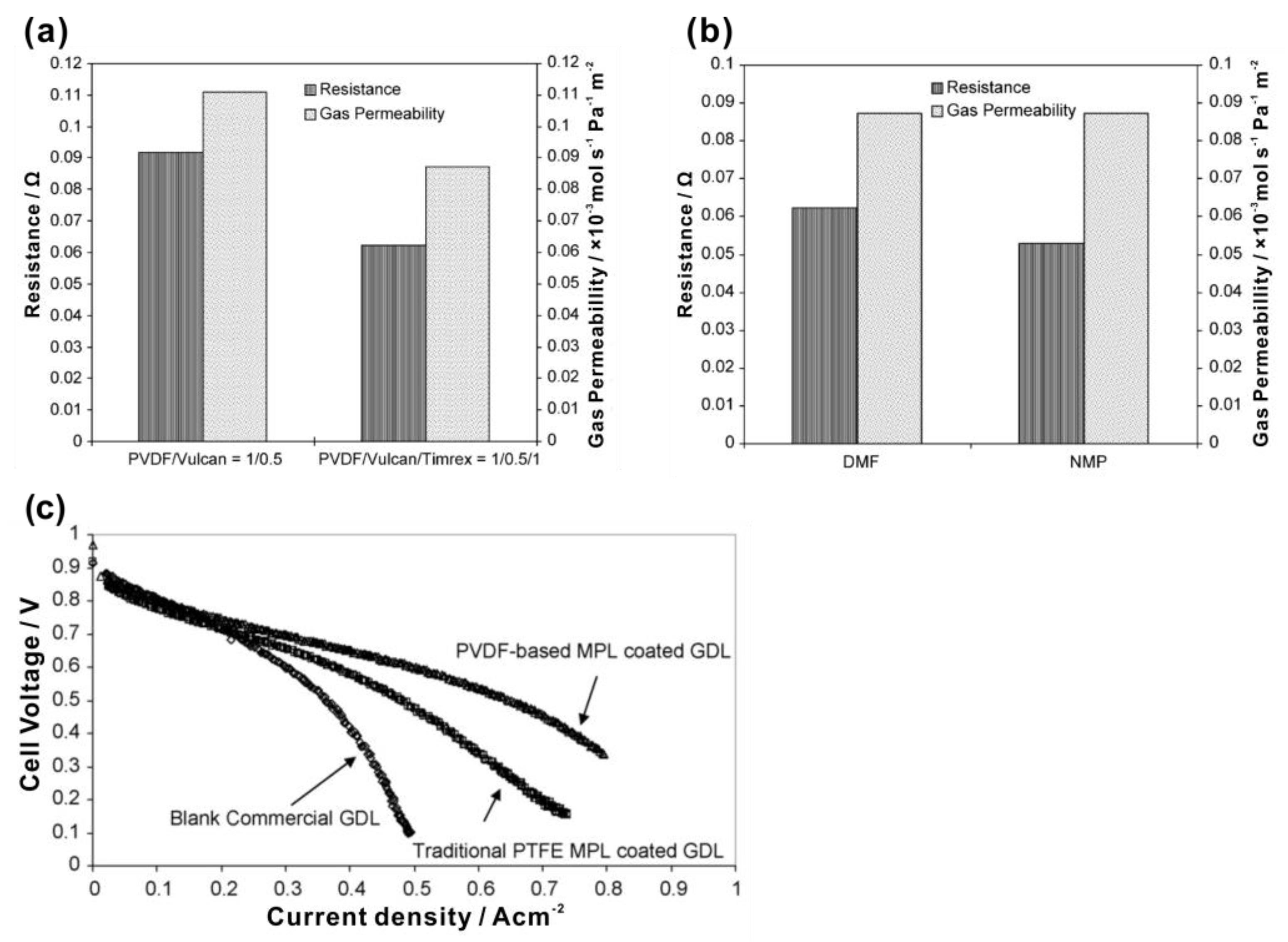
- Ong, A.L.; Bottino, A.; Capannelli, G.; Comite, A. Effect of preparative parameters on the characteristic of poly(vinylidene fluoride)-based microporous layer for proton exchange membrane fuel cells. J. Power Sources 2008, 183, 62–68. [Google Scholar] [CrossRef]
- Sim, J.; Kang, M.; Min, K. Effects of basic gas diffusion layer components on PEMFC performance with capillary pressure gradient. Int. J. Hydrogen Energy 2021, 46, 27731–27748. [Google Scholar] [CrossRef]
- Giorgi, L.; Antolini, E.; Pozio, A.; Passalacqua, E. Influence of the PTFE content in the diffusion layer of low-Pt loading electrodes for polymer electrolyte fuel cells. Electrochim. Acta 1998, 43, 3675–3680. [Google Scholar] [CrossRef]
- Qi, Z.G.; Kaufman, A. Improvement of water management by a microporous sublayer for PEM fuel cells. J. Power Sources 2002, 109, 38–46. [Google Scholar] [CrossRef]
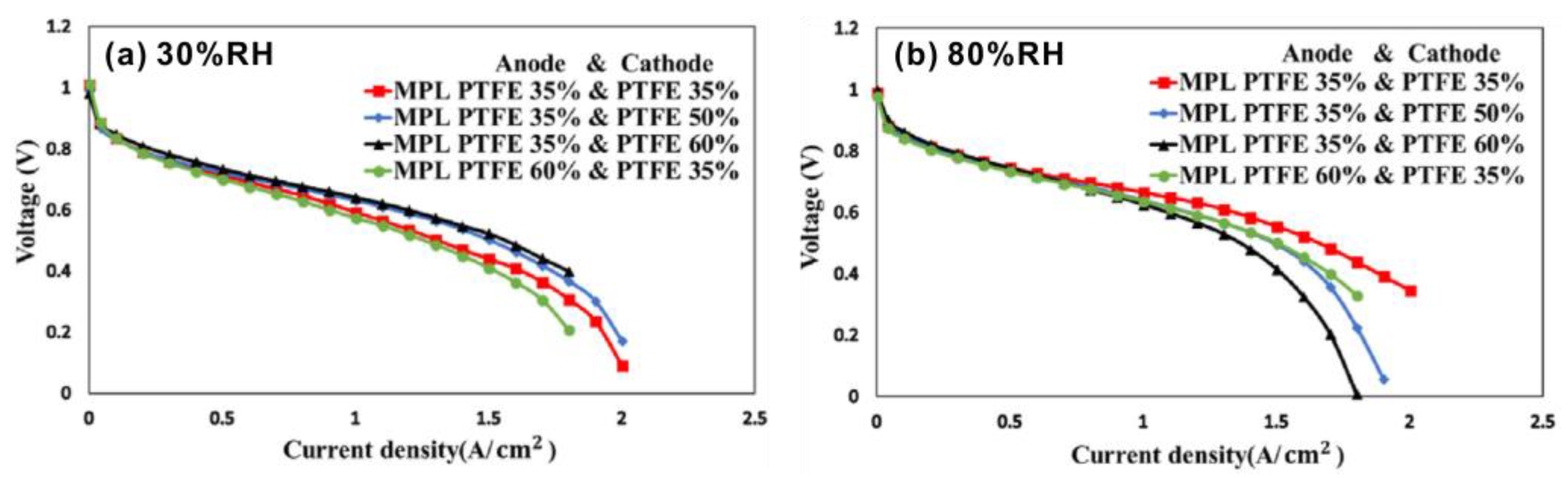
- Chen, T.; Liu, S.; Zhang, J.; Tang, M. Study on the characteristics of GDL with different PTFE content and its effect on the performance of PEMFC. Int. J. Heat Mass Transf. 2019, 128, 1168–1174. [Google Scholar] [CrossRef]
- Latorrata, S.; Cristiani, C.; Dotelli, G. Performance Evaluation and Durability Enhancement of FEP-Based Gas Diffusion Media for PEM Fuel Cells. Energies 2017, 10, 2063. [Google Scholar] [CrossRef] [Green Version]
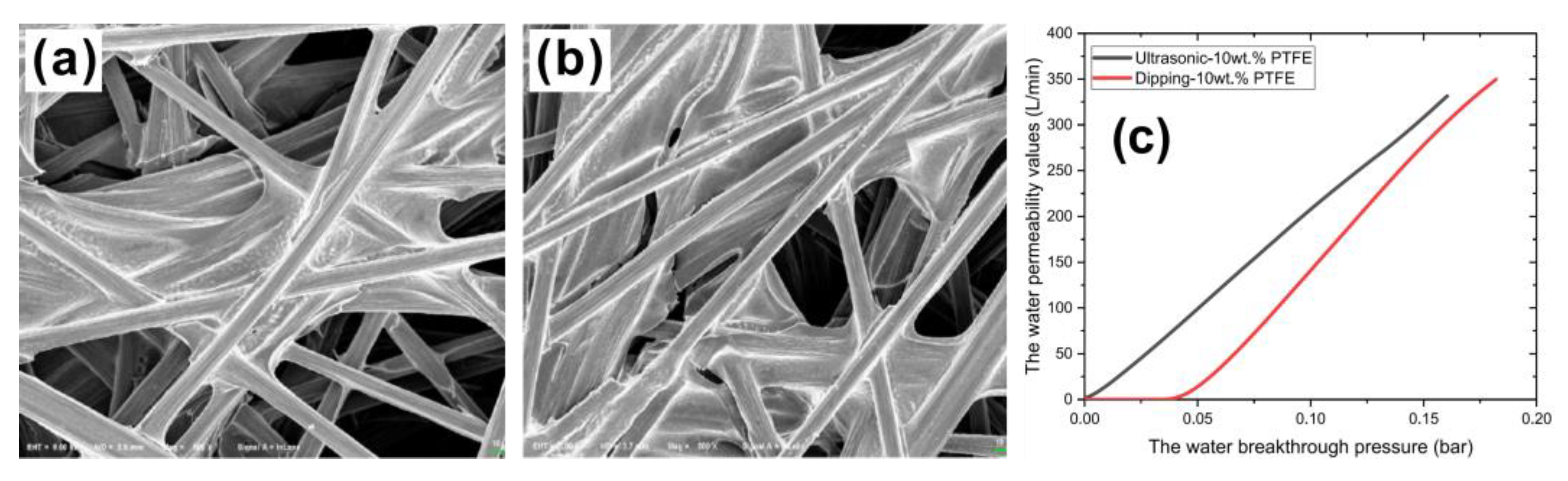
- Liu, S.; Guo, Y.; Kang, K.; Chen, Y.; Li, K. Theoretical and experimental study on the preparation of hydrophobic GDL materials by ultrasonic dispersion. Renew. Energy 2022, 181, 129–141. [Google Scholar] [CrossRef]
- Li, T.; Wang, K.; Wang, J.; Liu, Y.; Han, Y.; Xu, Z.; Lin, G.; Liu, Y. Optimization of GDL to improve water transferability. Renew. Energy 2021, 179, 2086–2093. [Google Scholar] [CrossRef]
- Wang, X.L.; Wang, W.K.; Qu, Z.G.; Ren, G.F.; Wang, H.C. Surface roughness dominated wettability of carbon fiber in gas diffusion layer materials revealed by molecular dynamics simulations. Int. J. Hydrogen Energy 2021, 46, 26489–26498. [Google Scholar] [CrossRef]
- Fan, M.; Duan, F.; Wang, T.; Kang, M.; Zeng, B.; Xu, J.; Anderson, R.; Du, W.; Zhang, L. Effect of Pore Shape and Spacing on Water Droplet Dynamics in Flow Channels of Proton Exchange Membrane Fuel Cells. Energies 2021, 14, 1250. [Google Scholar] [CrossRef]
- Kanchan, B.K.; Randive, P.; Pati, S. Implications of non-uniform porosity distribution in gas diffusion layer on the performance of a high temperature PEM fuel cell. Int. J. Hydrogen Energy 2021, 46, 18571–18588. [Google Scholar] [CrossRef]
- Anyanwu, I.S.; Niu, Z.; Jin, S.; Jiao, K.; Gong, Z.; Liu, Z. Analysis of compression in uniform and non-uniform GDL microstructures on water transport. Int. J. Green Energy 2021, 19, 1389–1403. [Google Scholar] [CrossRef]
- Wang, H.; Yang, G.; Li, S.; Shen, Q.; Liao, J.; Jiang, Z.; Espinoza-Andaluz, M.; Su, F.; Pan, X. Numerical study on permeability of gas diffusion layer with porosity gradient using lattice Boltzmann method. Int. J. Hydrogen Energy 2021, 46, 22107–22121. [Google Scholar] [CrossRef]
- Wang, H.; Yang, G.; Li, S.; Shen, Q.; Liao, J.; Jiang, Z.; Zhang, G.; Zhang, H.; Su, F. Transport-Parameter-Based Correlations for Gas Diffusion Layers Considering Compression and Binder: An Investigation Using the Lattice Boltzmann Method. Energy Fuels 2021, 36, 589–602. [Google Scholar] [CrossRef]
- Wang, H.; Yang, G.; Li, S.; Shen, Q.; Liao, J.; Jiang, Z.; Zhang, G.; Zhang, H.; Su, F. Effect of Binder and Compression on the Transport Parameters of a Multilayer Gas Diffusion Layer. Energy Fuels 2021, 35, 15058–15073. [Google Scholar] [CrossRef]
- Liao, J.; Yang, G.; Li, S.; Shen, Q.; Jiang, Z.; Wang, H.; Xu, L.; Espinoza-Andaluz, M.; Pan, X. Effect of Structural Parameters on Mass Transfer Characteristics in the Gas Diffusion Layer of Proton Exchange Membrane Fuel Cells Using the Lattice Boltzmann Method. Energy Fuels 2021, 35, 2654–2664. [Google Scholar] [CrossRef]
- Liao, J.; Yang, G.; Shen, Q.; Li, S.; Jiang, Z.; Wang, H.; Sheng, Z.; Zhang, G.; Zhang, H. Effects of the Structure, Wettability, and Rib-Channel Width Ratio on Liquid Water Transport in Gas Diffusion Layer Using the Lattice Boltzmann Method. Energy Fuels 2021, 35, 16799–16813. [Google Scholar] [CrossRef]
- Zhu, L.; Zhang, H.; Xiao, L.; Bazylak, A.; Gao, X.; Sui, P.-C. Pore-scale modeling of gas diffusion layers: Effects of compression on transport properties. J. Power Sources 2021, 496, 229822. [Google Scholar] [CrossRef]
- Xie, X.; Yin, B.; Xu, S.; Chen, X.; Dong, F.; Yu, Y.; Zhang, X.; Jia, H. Influence of perforated gas diffusion layer micropore shape parameters on water removal in a proton exchange membrane fuel cell flow channel. Int. J. Energy Res. 2021, 45, 14630–14643. [Google Scholar] [CrossRef]
- Liu, S.; Zhang, L.; Wang, Z.; Dong, F.; Zhao, Q.; Zhang, Q. Effect of hydrophilic pipe structure of proton exchange membrane fuel cell on water removal from the gas diffusion layer surface. Int. J. Hydrogen Energy 2021, 46, 30442–30454. [Google Scholar] [CrossRef]
- Ira, Y.; Bakhshan, Y.; Khorshidimalahmadi, J. Effect of wettability heterogeneity and compression on liquid water transport in gas diffusion layer coated with microporous layer of PEMFC. Int. J. Hydrogen Energy 2021, 46, 17397–17413. [Google Scholar] [CrossRef]
- Hou, Y.; Li, X.; Du, Q.; Jiao, K.; Zamel, N. Pore-Scale Investigation of the Effect of Micro-Porous Layer on Water Transport in Proton Exchange Membrane Fuel Cell. J. Electrochem. Soc. 2020, 167, 144504. [Google Scholar] [CrossRef]
- Lin, G.; Liu, S.; Yu, B.; Wang, H.; Yu, K.; Hu, Y. Preparation of graded microporous layers for enhanced water management in fuel cells. J. Appl. Polym. Sci. 2020, 137, 49564. [Google Scholar] [CrossRef]
- Tseng, C.-J.; Lo, S.-K. Effects of microstructure characteristics of gas diffusion layer and microporous layer on the performance of PEMFC. Energy Convers. Manag. 2010, 51, 677–684. [Google Scholar] [CrossRef]
- Lin, G.; Liu, S.; Qu, S.; Qu, G.; Li, T.; Liang, Z.; Hu, Y.; Liu, F. Effects of thickness and hydrophobicity of double microporous layer on the performance in proton exchange membrane fuel cells. J. Appl. Polym. Sci. 2020, 138, 50355. [Google Scholar] [CrossRef]
- Mathur, R.B.; Maheshwari, P.H.; Dhami, T.L.; Sharma, R.K.; Sharma, C.P. Processing of carbon composite paper as electrode for fuel cell. J. Power Sources 2006, 161, 790–798. [Google Scholar] [CrossRef]
- Mathur, R.B.; Maheshwari, P.H.; Dhami, T.L.; Tandon, R.P. Characteristics of the carbon paper heat-treated to different temperatures and its influence on the performance of PEM fuel cell. Electrochim. Acta 2007, 52, 4809–4817. [Google Scholar] [CrossRef]
- Wang, Y.; Zhang, P.; Gao, Y.; He, W.; Zhao, Y.; Wang, X. Optimal design of cathode gas diffusion layer with arrayed grooves for performance enhancement of a PEM fuel cell. Renew. Energy 2022, 199, 697–709. [Google Scholar] [CrossRef]
- Chen, H.; Guo, H.; Ye, F.; Ma, C.F. Modification of the two-fluid model and experimental study of proton exchange membrane fuel cells with baffled flow channels. Energy Convers. Manag. 2019, 195, 972–988. [Google Scholar] [CrossRef]
- Moradizadeh, L.; Paydar, M.H.; Yazdanpanah, P.; Karimi, G. Fabrication and characterization of metal-based gas diffusion layer containing rGO and graphite for proton exchange membrane fuel cells. Int. J. Energy Res. 2022, 46, 11027–11040. [Google Scholar] [CrossRef]
- Zhang, L.; Liu, Y.; Song, H.; Wang, S.; Zhou, Y.; Hu, S.J. Estimation of contact resistance in proton exchange membrane fuel cells. J. Power Sources 2006, 162, 1165–1171. [Google Scholar] [CrossRef]
- Bates, A.; Mukherjee, S.; Hwang, S.; Lee, S.C.; Kwon, O.; Choi, G.H.; Park, S. Simulation and experimental analysis of the clamping pressure distribution in a PEM fuel cell stack. Int. J. Hydrogen Energy 2013, 38, 6481–6493. [Google Scholar] [CrossRef]
- Shu, Q.-Z.; Xia, Z.-X.; Wei, W.; Xu, X.-L.; Wang, S.-L.; Zhao, H.; Sun, G.-Q. A novel gas diffusion layer and its application to direct methanol fuel cells. New Carbon Mater. 2021, 36, 409–419. [Google Scholar] [CrossRef]
- Wang, X.C.; Ma, H.L.; Peng, H.Q.; Wang, Y.M.; Wang, G.W.; Xiao, L.; Lu, J.T.; Zhuang, L. Enhanced mass transport and water management of polymer electrolyte fuel cells via 3-D printed architectures. J. Power Sources 2021, 515, 230636. [Google Scholar] [CrossRef]
- Lim, I.S.; Kang, B.; Park, J.Y.; Kim, M.S. Performance improvement of polymer electrolyte membrane fuel cell by gas diffusion layer with atomic-layer-deposited HfO2 on microporous layer. Energy Convers. Manag. 2021, 236, 114070. [Google Scholar] [CrossRef]
- Liu, Z.C.; Zhou, L.; Gao, Y.Y.; Qi, M.M.; Chen, H.P.; Hou, M.; Shao, Z.G. A novel hydrophilic-modified gas diffusion layer for proton exchange membrane fuel cells operating in low humidification. Int. J. Energy Res. 2021, 45, 16874–16883. [Google Scholar] [CrossRef]
- Fu, X.W.; Wei, J.; Ning, F.D.; Bai, C.; Wen, Q.L.; Jin, H.Q.; Li, Y.L.; Zou, S.Y.; Pan, S.F.; Chen, J.F.; et al. Highly flat and highly homogeneous carbon paper with ultra-thin thickness for high-performance proton exchange membrane fuel cell (PEMFC). J. Power Sources 2022, 520, 230832. [Google Scholar] [CrossRef]
- Wang, M.L.; Hou, M.; Gao, Y.Y.; Chen, H.P.; Lv, B.; Song, W.; Shao, Z.G. Study of substrate-free microporous layer of proton exchange membrane fuel cells. Int. J. Energy Res. 2022, 46, 9782–9793. [Google Scholar] [CrossRef]
- Navarro, A.J.; Gomez, M.A.; Daza, L.; Lopez-Cascales, J.J. Production of gas diffusion layers with cotton fibers for their use in fuel cells. Sci. Rep. 2022, 12, 4219. [Google Scholar] [CrossRef]


| Authors | Method | Focus | Conclusion |
|---|---|---|---|
| Fan et al. [81] | CFD, VOF | Pore shapes and pore distance. | The pentagon and the hexagon pore structure decrease the droplet volume, pressure drop and cycle time. When pore distance is >0.6 mm, pressure drop increases sharply. |
| Kanchan et al. [82] | 3D single-phase isothermal model | Stepwise, sinusoidal, and logarithmic non-uniform porosity configurations. | When logarithmic porosity decreasing configuration occurs in GDL, power density, current density and average diffusion coefficient reach the maximum. |
| Anyanwu et al. [83] | FVM, VOF | Compression ratio and fiber diameter | The effect of 10% compression ratio (CR) on liquid water saturation drop is relatively small (~8%). The effect of fiber diameter difference on water transport under compression is limited. |
| Wang et al. [84] | LBM | Linear type, stepped type and Transitional type non-uniform porosity configurations. | Linear porosity gradient distribution gives higher permeability than the others, and the maximum permeability is increased by 26.33%. |
| Wang et al. [85,86] | LBM | Binder and compression ratio. | The increase of volume fractions of binders (BVF) and CR reduce the permeability but increase the electric conductivity. |
| Liao et al. [87,88] | LBM | Diameter of the carbon fiber, porosity and thickness. | Diffusion characteristics of the GDL does not change obviously with the diameter of the carbon fiber and thickness increasing. However, the porosity increasing from 60 to 80% benefits the diffusion characteristics and leads to an increasing water saturation in GDL by 198.92%. |
| Zhu et al. [89] | PSM, LBM | Compression ratio. | Using 20% CR gets the best performance, considering gas diffusivity, effective electric and thermal conductivities. |
| Xie et al. [90] | VOF | Flow channel. | The flow channel with 50 μm in depth, 50 μm in radius and 200 μm in spacing has good drainage performance. |
| Liu et al. [91] | VOF | Flow channel. | The hydrophilic pipe with 400 μm in height, 37.5 μm in radius and 300 μm in spacing has good drainage performance. |
| Ira et al. [92] | LBM | Hydrophilic fibers percentage and compression ratio. | Using 10% hydrophilic fibers and 10% CR decreases the saturation level by 5.2% and shortens the time to reach steady-state by 22%. |
| Authors | Approach | Contact Angle | Pore Size Distribution | Electrochemical Performance | Advantages |
|---|---|---|---|---|---|
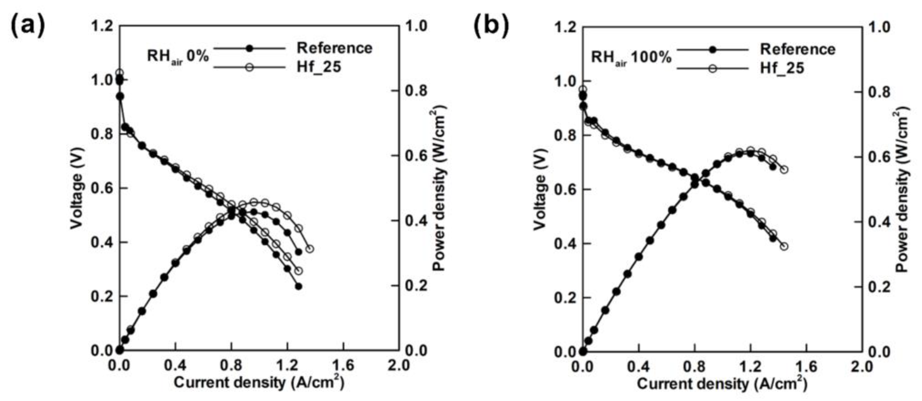
| Lim et al. [106] | Using ALD to modify GDL by depositing HfO2 onto MPL | Reference GDL: 155°; GDL deposited with HfO2 (HF_25): 137° | Distribution into two regions: 10–25 μm and 0.05 μm | The peak power density is improved by 7% in low RH atmosphere and 1.6% in high RH atmosphere. | Performance of PEMFC in low humidity is improved. |
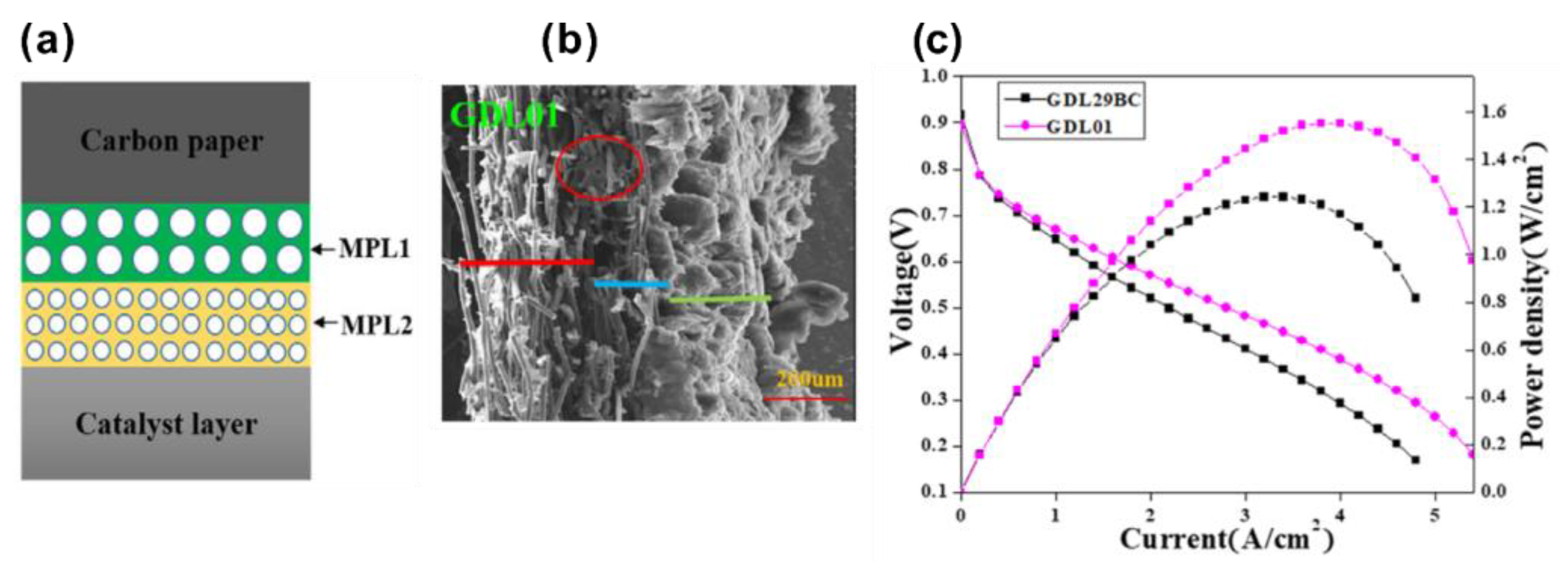
| Liu et al. [107] | adding PAN into the MPL | No PAN: 144°; 1 wt% PAN: 136.46°; 3 wt% PAN: 125.59° | Distribution into two regions: 20–70 nm and 0.06–0.1 nm | The peak power density of PEMFCs without PAN and containing 3 wt% PAN are 0.480 and 0.616 Wcm−2, respectively in low RH. | The performance of PEMFC in low PH is improved by adding PAN into the GDL. |
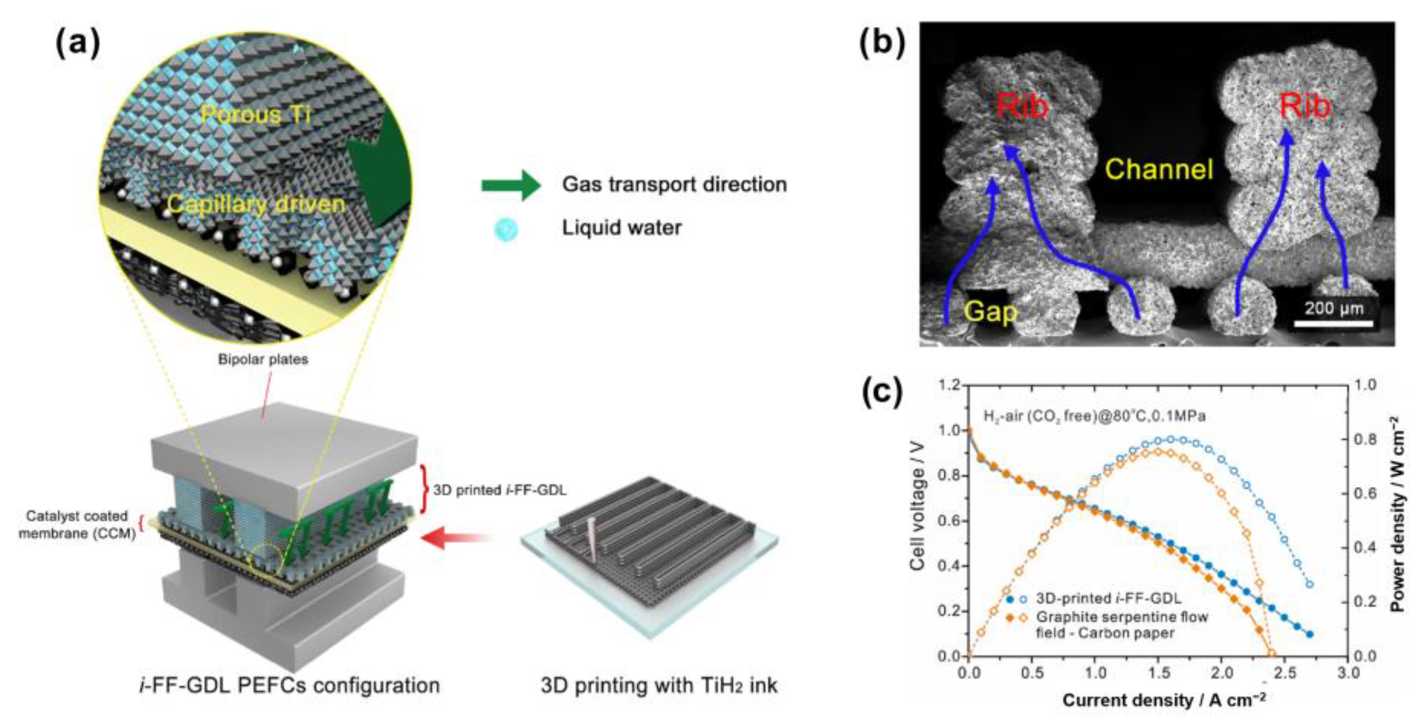
| Wang et al. [105] | GDL 3D-printed with TiH2 added. | - | In high current density region (>1 Acm−2), the peak power density increases by 15% and 8% by using i-FF-GDL under H2–O2 and H2-air (CO2 free) condition. | This 3D GDL separates gas and liquid flow channels by its “bone” structure | |
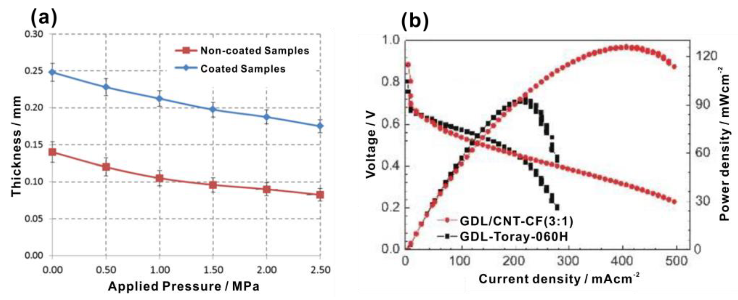
| Fu et al. [108] | Carbon paper prepared by mixing FWCNT with short CF | - | The peak power density using new carbon papers is up to 365 mWcm−2, higher than 205 mWcm−2 for commercial carbon paper. | The heat treatment temperature (350 °C) is much lower than the traditional temperature (2000 °C). The flatness was improved to be <6.4 μm. | |
| Wang et al. [109] | Dry-pressing method using CF and PVDF | 139.4° | 100–1000 nm | 785 mWcm−2 in 40% RH, 1091 mWcm−2 in 100% RH. | The performance of PEMFC in low humidity is improved. |
| Navarro et al. [110] | Adding natural cotton to GDL | GDL with 40% cotton content: 170°. | GDL with 40% cotton content: 11,000–13,000 nm | The in-plane electrical conductivity of the GDL with 40% cotton is close to 4421 ± 160 Sm−1. | Low cost |
Publisher’s Note: MDPI stays neutral with regard to jurisdictional claims in published maps and institutional affiliations. |
© 2022 by the authors. Licensee MDPI, Basel, Switzerland. This article is an open access article distributed under the terms and conditions of the Creative Commons Attribution (CC BY) license (https://creativecommons.org/licenses/by/4.0/).
Share and Cite
Guo, H.; Chen, L.; Ismail, S.A.; Jiang, L.; Guo, S.; Gu, J.; Zhang, X.; Li, Y.; Zhu, Y.; Zhang, Z.; et al. Gas Diffusion Layer for Proton Exchange Membrane Fuel Cells: A Review. Materials 2022, 15, 8800. https://doi.org/10.3390/ma15248800
Guo H, Chen L, Ismail SA, Jiang L, Guo S, Gu J, Zhang X, Li Y, Zhu Y, Zhang Z, et al. Gas Diffusion Layer for Proton Exchange Membrane Fuel Cells: A Review. Materials. 2022; 15(24):8800. https://doi.org/10.3390/ma15248800
Chicago/Turabian StyleGuo, Hui, Lubing Chen, Sara Adeeba Ismail, Lulu Jiang, Shihang Guo, Jie Gu, Xiaorong Zhang, Yifeng Li, Yuwen Zhu, Zihan Zhang, and et al. 2022. "Gas Diffusion Layer for Proton Exchange Membrane Fuel Cells: A Review" Materials 15, no. 24: 8800. https://doi.org/10.3390/ma15248800
APA StyleGuo, H., Chen, L., Ismail, S. A., Jiang, L., Guo, S., Gu, J., Zhang, X., Li, Y., Zhu, Y., Zhang, Z., & Han, D. (2022). Gas Diffusion Layer for Proton Exchange Membrane Fuel Cells: A Review. Materials, 15(24), 8800. https://doi.org/10.3390/ma15248800