
A Semi-Active Control Technique through MR Fluid Dampers for Seismic Protection of Single-Story RC Precast Buildings


Abstract
:1. Introduction
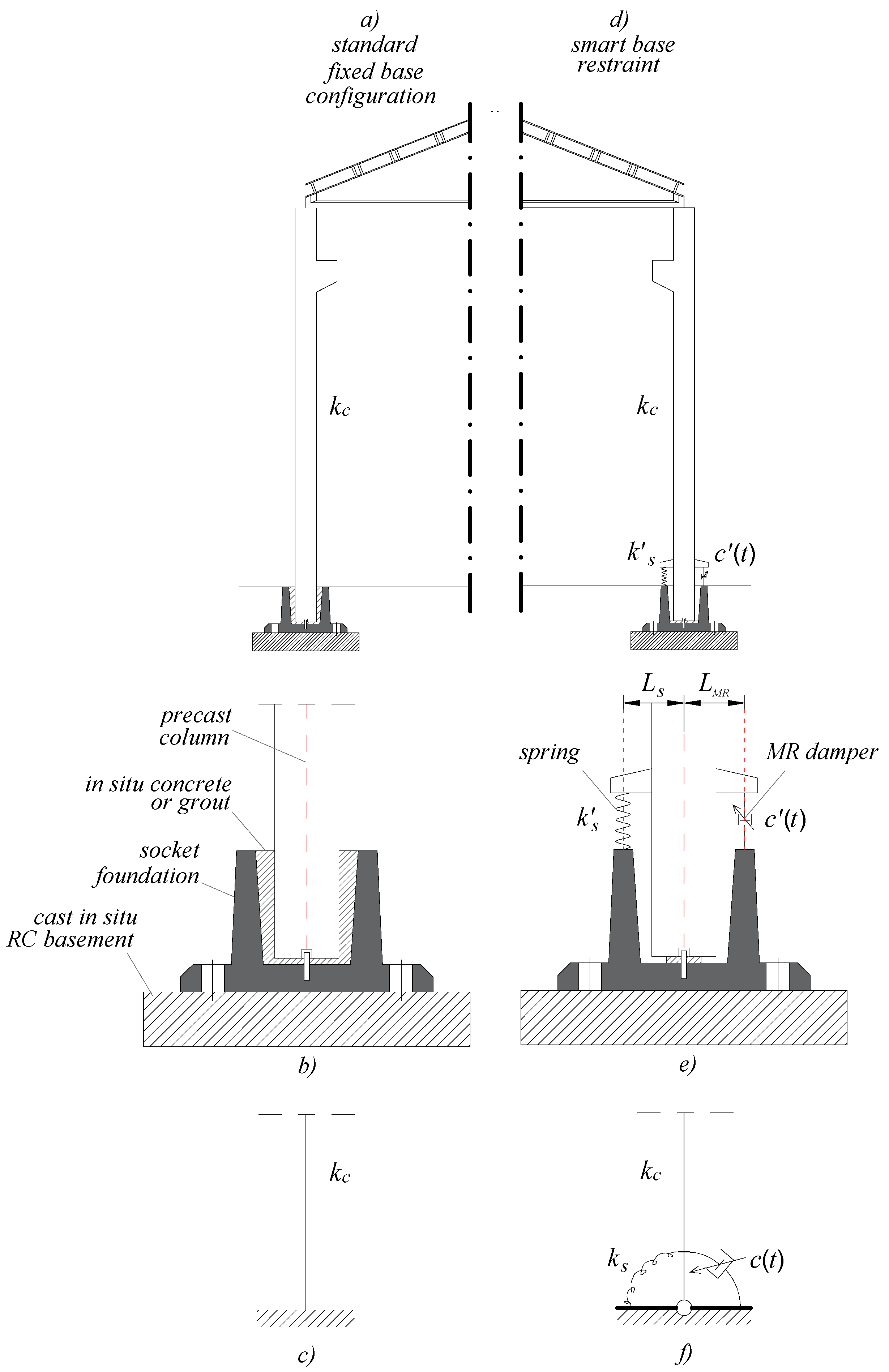
2. The Proposed Control Strategy
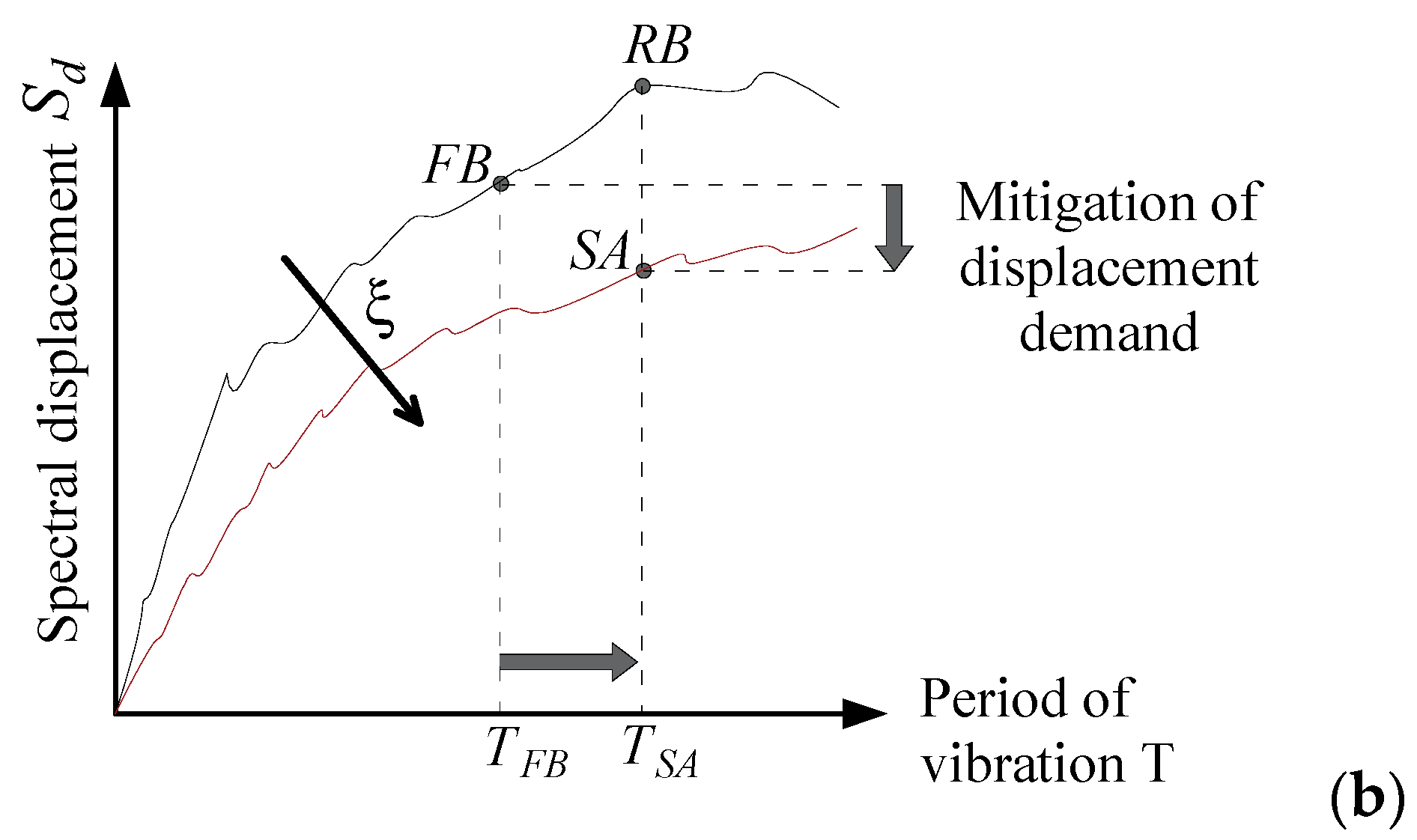
- In the rigid configuration (“fixed base”, (FB)), the MR devices are powered with the maximum current (briefly, state “ON” in the following) and therefore exhibit a very rigid behavior; this, in essence, limits the base rotation;
- In the dissipative configuration (“semi-active”, (SA)), the devices are fed with a lower intensity (briefly, state “OFF” in the following) and then basically behave like non-linear viscous dampers; in this case, the base rotates, the springs react elastically, and the dampers dissipate energy, thus reducing the structural response.
- (1)
- Reducing the bending moment demand in the columns;
- (2)
- Limiting the top displacement demand within given limits, to avoid the damage of nonstructural elements as well as to limit detrimental second-order effects.
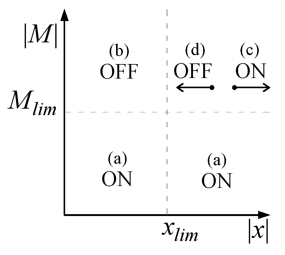
- For displacements lower than xlim, the damping is set to the minimum value so as to enable base rocking and to induce energy dissipation (case (b) in Equation (1) and Figure 4);
- When the displacement is greater than xlim and is still growing (i.e., the velocity ẋ(t) has the same sign), the damping is set to maximum so as to make the base restraint stiffer and to prevent the displacement from rising again (case (c) in Equation (1) and Figure 4);
- When the displacement is greater than xlim but is decreasing (i.e., the velocity ẋ(t) is in the opposite direction), the damping is set to minimum to achieve energy dissipation into the damper (case (d) in Equation (1) and Figure 4).
3. Calibration of the Control Strategy: Application to a Case Study Structure
- xlim, limit value displacement at the top of the column;
- Mlim, limit value of base bending moment for the column;
- ks, stiffness of the base spring;
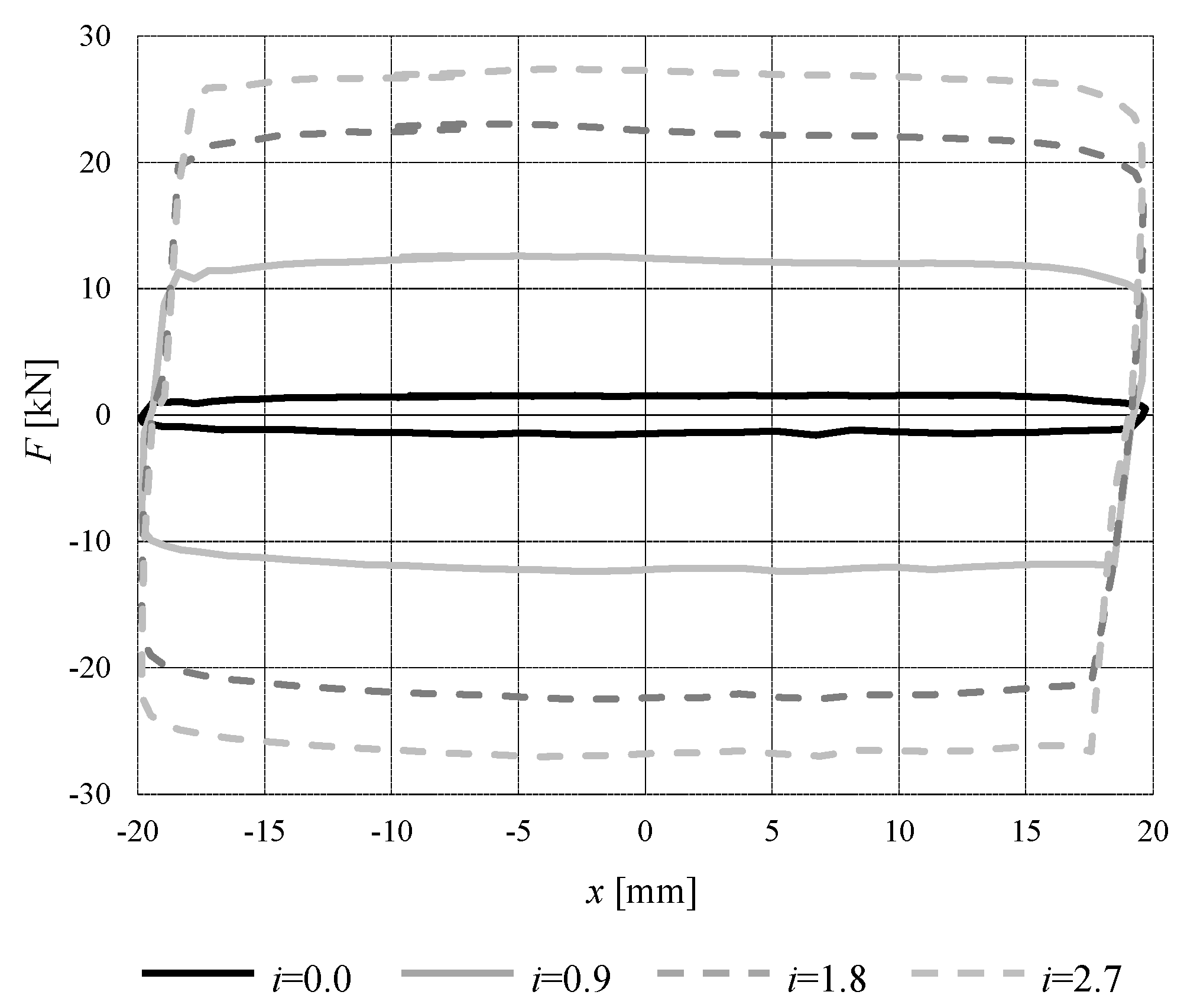
- cON, the damping capability of the MR damper in the ON state (details in Section 3.4);
- cOFF, the damping capability of the MR damper in the OFF state (details in Section 3.4).
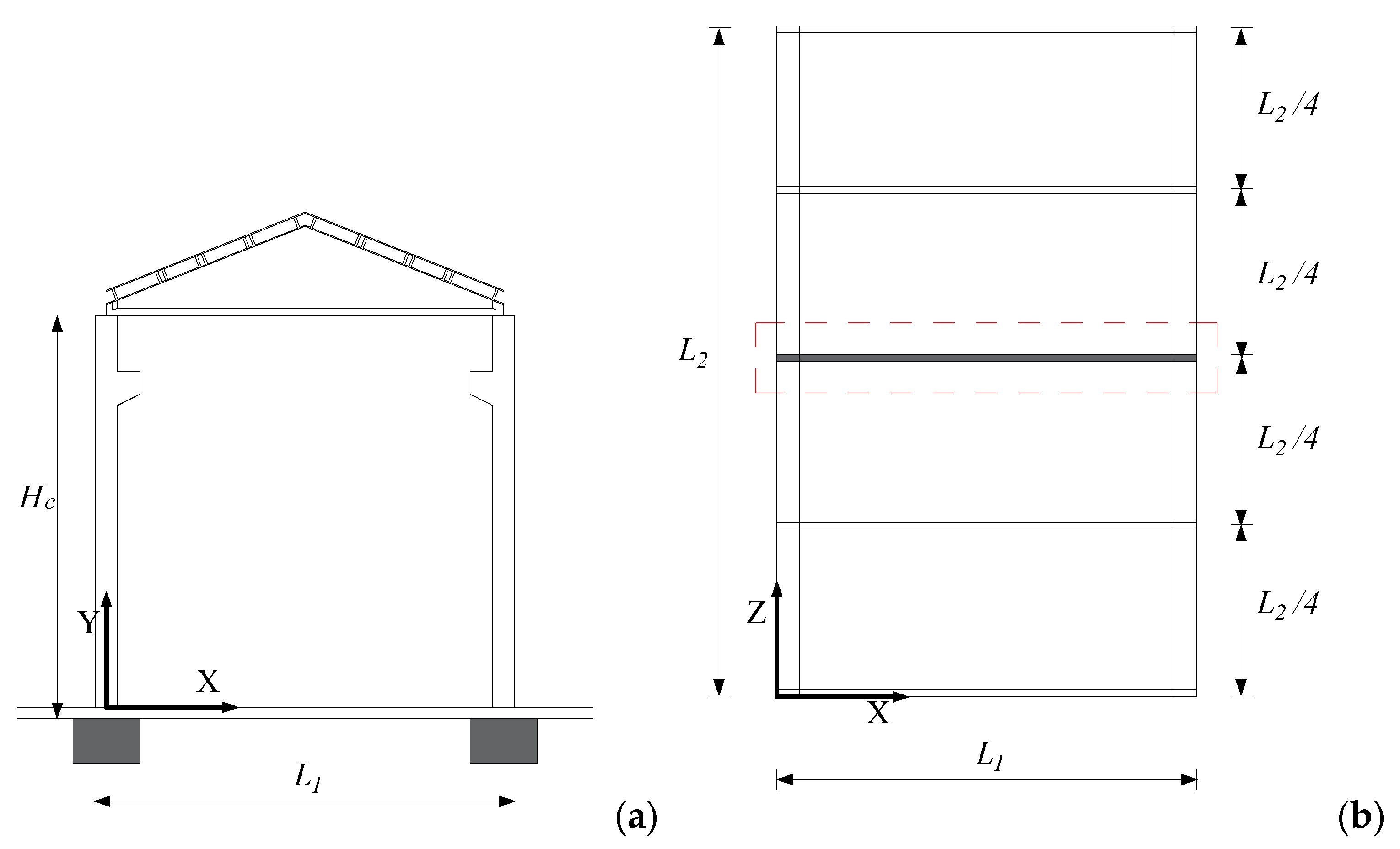
3.1. Case Study Structure
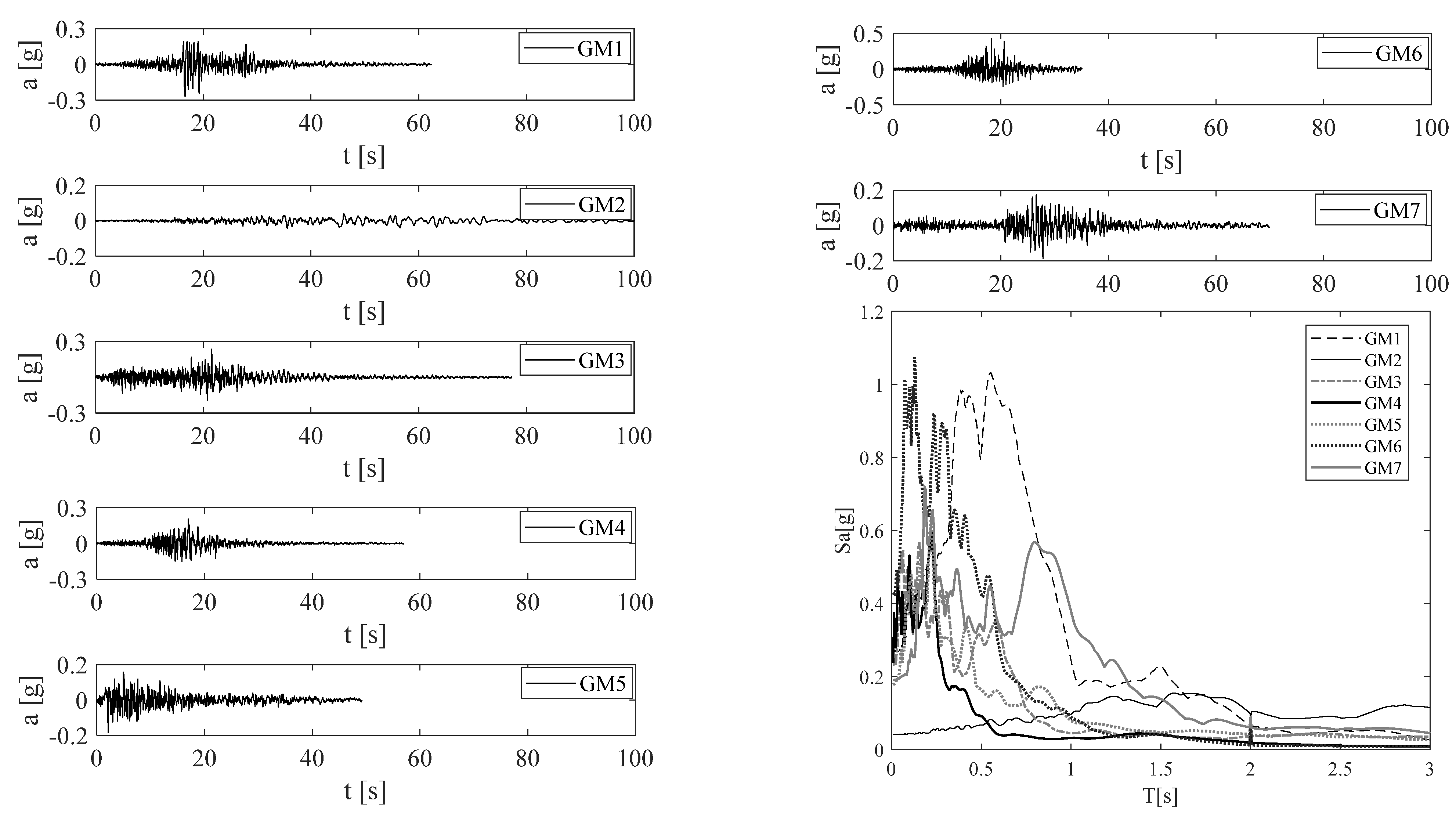
3.2. Seismic Loads
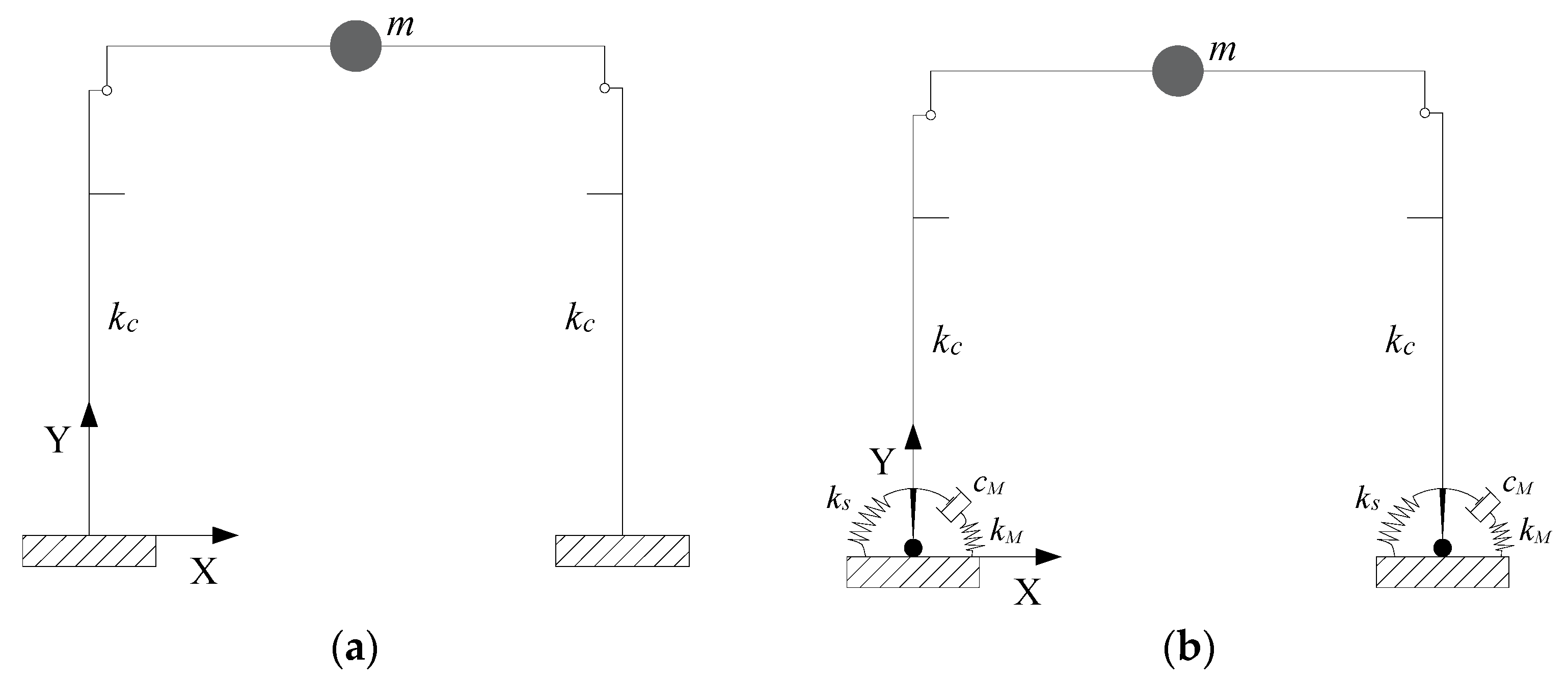
3.3. Numerical Modelling
3.4. Calibration of the Controller and Numerical Simulations
- (1)
- The largest reduction of the bending moment at the base of the columns;
- (2)
- To limit any increase in displacement demand, so that the maximum value was at most equal to that of the fixed base state increased by 30% (allowed tolerance), in any case lower than the yielding displacement (200 mm).
4. Conclusions
Author Contributions
Funding
Institutional Review Board Statement
Informed Consent Statement
Data Availability Statement
Conflicts of Interest
References and Note
- Magliulo, G.; Ercolino, M.; Petrone, C.; Coppola, O.; Manfredi, G. Emilia Earthquake: The Seismic Performance of Precast RC Buildings. Earthq. Spectra 2014, 30, 891–912. [Google Scholar] [CrossRef]
- Ercolino, M.; Magliulo, G.; Manfredi, G. Failure of a precast RC building due to Emilia-Romagna earthquakes. Eng. Struct. 2016, 118, 262–273. [Google Scholar] [CrossRef]
- Keshtegar, B.; Nehdi, M.L.; Trung, N.-T.; Kolahchi, R. Predicting load capacity of shear walls using SVR–RSM model. Appl. Soft Comput. 2021, 112, 107739. [Google Scholar] [CrossRef]
- Marriott, D.; Pampanin, S.; Bull, D.; Palermo, A. Improving the seismic performance of existing reinforced concrete buildings using advanced rocking wall solutions. In Proceedings of the 2007 NZSEE Conference, Palmerston North, New Zealand, 30 March–1 April 2007; NZSEE: Wellington, New Zealand, 2007. [Google Scholar]
- Mazza, F. Dissipative steel exoskeletons for the seismic control of reinforced concrete framed buildings. Struct. Control Health Monit. 2021, 28, e2683. [Google Scholar] [CrossRef]
- Al-Furjan, M.; Hajmohammad, M.H.; Shen, X.; Rajak, D.K.; Kolahchi, R. Evaluation of tensile strength and elastic modulus of 7075-T6 aluminum alloy by adding SiC reinforcing particles using vortex casting method. J. Alloy. Compd. 2021, 886, 161261. [Google Scholar] [CrossRef]
- Casotto, C.; Silva, V.; Crowley, H.; Nascimbene, R.; Pinho, R. Seismic fragility of Italian RC precast industrial structures. Eng. Struct. 2015, 94, 122–136. [Google Scholar] [CrossRef]
- Magliulo, G.; Cimmino, M.; Ercolino, M.; Manfredi, G. Cyclic shear tests on RC precast beam-to-column connections retrofitted with a three-hinged steel device. Bull. Earthq. Eng. 2017, 15, 3797–3817. [Google Scholar] [CrossRef] [Green Version]
- Martinelli, P.; Mulas, M.G. An innovative passive control technique for industrial precast frames. Eng. Struct. 2010, 32, 1123–1132. [Google Scholar] [CrossRef]
- Minghini, F.; Tullini, N. Seismic retrofitting solutions for precast RC industrial buildings struck by the 2012 earth-quakes in Northern Italy. Front. Built Environ. 2021, 7, 631315. [Google Scholar] [CrossRef]
- Murahidy, A.G.; Spieth, H.A.; Carr, A.J.; Mander, J.B. Design, construction and dynamic testing of a post-tensioned pre-cast reinforced concrete frame building with rocking beam-column connections and ADAS Elements. In Proceedings of the 2004 NZSEE Conference, Rotorua, New Zealand, 19–21 March 2004; NZSEE: Wellington, New Zealand, 2004. [Google Scholar]
- Decreto legge 6 giugno 2012 n. 74, Interventi urgenti in favore delle popolazioni colpite dagli eventi sismici che hanno interessato il territorio delle province di Bologna, Modena, Ferrara, Mantova, Reggio Emilia e Rovigo, il 20 e il 29 maggio 2012. (In Italian)
- Pampanin, S. Reality-check and renewed challenges in earthquake engineering. Bull. N. Z. Soc. Earthq. Eng. 2012, 45, 137–160. [Google Scholar] [CrossRef]
- Spieth, H.; Arnold, D.; Davies, M.; Mander, J.; Carr, A. Seismic performance of post-tensioned precast concrete beam to column connections with supplementary energy dissipation. In Proceedings of the NZSEE Conference, Rotorua, New Zealand, 19–21 March 2004; NZSEE: Wellington, New Zealand, 2004. [Google Scholar]
- Belleri, A.; Schoettler, M.J.; Restrepo, J.I.; Fleishman, R.B. Dynamic Behavior of Rocking and Hybrid Cantilever Walls in a Precast Concrete Building; American Concrete Institute: Farmington Hills, MI, USA, 2014. [Google Scholar]
- Lu, L.; Liu, X.; Chen, J.; Lu, X. Seismic performance of a controlled rocking reinforced concrete frame. Adv. Struct. Eng. 2016, 20, 4–17. [Google Scholar] [CrossRef]
- Masrom, M.A.; Hamid, N.H.A. Review on the rocking wall systems as a self-centering mechanism and its interaction with floor diaphragm in precast concrete structures. Lat. Am. J. Solids Struct. 2020, 17, 4–17. [Google Scholar] [CrossRef]
- Zhao, Z.; Su, X. Seismic Response Analysis of Prestressed Concrete Rocking Frame. Appl. Sci. 2021, 11, 585. [Google Scholar] [CrossRef]
- Marriott, D.; Pampanin, S.; Bull, D.; Palermo, A. Dynamic testing of precast, post-tensioned rocking wall systems with alternative dissipating solutions. Bull. New Zealand Soc. Earthq. Eng. 2008, 41, 90–103. [Google Scholar] [CrossRef] [Green Version]
- Jiang, Q.; Wang, H.; Feng, Y.; Chong, X.; Huang, J.; Liu, Y. Enhancing the Seismic Performance of Precast RC Frames with Cladding Panels through Setting U-Shaped Dampers and Rocking Walls. Shock. Vib. 2020, 2020, 4182094. [Google Scholar] [CrossRef]
- Kurama, Y.C.; Sritharan, S.; Fleischman, R.B.; Restrepo, J.I.; Henry, R.S.; Cleland, N.M.; Ghosh, S.K.; Bonelli, P. Seismic-Resistant Precast Concrete Structures: State of the Art. J. Struct. Eng. 2018, 144, 03118001. [Google Scholar] [CrossRef] [Green Version]
- Caterino, N. Semi-active control of a wind turbine via magnetorheological dampers. J. Sound Vib. 2015, 345, 1–17. [Google Scholar] [CrossRef]
- Caterino, N.; Georgakis, C.T.; Spizzuoco, M.; Occhiuzzi, A. Design and calibration of a semi-active control logic to mitigate structural vibrations in wind turbines. Smart Struct. Syst. 2016, 18, 75–92. [Google Scholar] [CrossRef]
- Caterino, N.; Spizzuoco, M.; Occhiuzzi, A. Understanding and modelling the physical behaviour of magnetorheologi-cal dampers for seismic structural control. Smart Mater. Struct. 2011, 20, 065013. [Google Scholar] [CrossRef]
- Magliulo, G.; Fabbrocino, G.; Manfredi, G. Seismic assessment of existing precast industrial buildings using static and dynamic nonlinear analyses. Eng. Struct. 2008, 30, 2580–2588. [Google Scholar] [CrossRef]
- Lin, T.; Haselton, C.B.; Baker, J.W. Conditional spectrum-based ground motion selection. Part I: Hazard consistency for risk-based assessments. Earthq. Eng. Struct. Dyn. 2013, 42, 1847–1865. [Google Scholar] [CrossRef] [Green Version]
- Lin, T.; Haselton, C.B.; Baker, J.W. Conditional spectrum-based ground motion selection. Part II: Intensity-based assessments and evaluation of alternative target spectra. Earthq. Eng. Struct. Dyn. 2013, 42, 1867–1884. [Google Scholar] [CrossRef] [Green Version]
- Iervolino, I.; Spillatura, A.; Bazzurro, P. RINTC project: Assessing the (implicit) seismic risk of code-conforming structures in Italy. In Proceedings of the ECCOMAS Thematic Conference on Computational Methods in Structural Dynamics and Earthquake Engineering, Rhodes Island, Greece, 15–17 June 2017. [Google Scholar]
- Ministero delle Infrastrutture. D.M. 17/01/2018—Norme Tecniche per le Costruzioni, G.U. n. 42/2018; Ministero Delle Infrastrutture: Rome, Italy, 2018. (In Italian) [Google Scholar]
- McKenna, F.; Fenves, G.L.; Scott, M.H. OpenSees: Open System for Earthquake Engineering Simulation; University of California: Berkeley, CA, USA, 2000; Available online: http://opensees.berkeley.edu (accessed on 10 May 2021).
- Chen, Z.; Yang, P.; Liu, H.; Zhang, W.; Wu, C. Characteristics analysis of granular landslide using shaking table model test. Soil Dyn. Earthq. Eng. 2019, 126, 105761. [Google Scholar] [CrossRef]
- Zhang, W.G.; Meng, F.S.; Chen, F.Y.; Liu, H.L. Effects of spatial variability of weak layer and seismic random-ness on rock slope stability and reliability analysis. Soil Dyn. Earthq. Eng. 2021, 146, 106735. [Google Scholar] [CrossRef]


| No. | Record Serial Number | Earthquake | Year | Station Name | Magnitude Mw | Epicentral Distance [km] | PGA [g] | SF [-] |
|---|---|---|---|---|---|---|---|---|
| 1 | 1304 | Chi-Chi, Taiwan | 1999 | HWA059 | 7.62 | 70 | 0.132 | 1.9 |
| 2 | 1398 | Chi-Chi, Taiwan | 1999 | KAU087 | 7.62 | 147 | 0.030 | 1.3 |
| 3 | 1788 | Hector Mine | 1999 | Hemet Fire Station | 7.13 | 117 | 0.058 | 3.6 |
| 4 | 1783 | Hector Mine | 1999 | Fort Irwin | 7.13 | 84 | 0.116 | 1.6 |
| 5 | 15 | Kern County | 1952 | Taft Lincoln School | 7.36 | 43 | 0.164 | 1.0 |
| 6 | 1067 | Northridge-01 | 1994 | San Bernardino-CSUSB Gr | 6.69 | 114 | 0.052 | 6.2 |
| 7 | 3823 | Hector Mine | 1999 | Universal City-Hwy 101 | 7.13 | 200 | 0.035 | 5.2 |
| Parameter | Criterion for Optimal Value * |
|---|---|
| Mlim | 0.08 Mmax,FB |
| xlim | 0.5 xmax,FB |
| cON | 0.08 Mmax,FB |
| cOFF | cON/5000 |
| kM | 10 cON/Δt |
| ks | kc |
| GM | Mmax,FB | xmax,FB | Control System Optimal Parameters | |
|---|---|---|---|---|
| [kNm] | [mm] | |||
| 1 | 829 | 90 | Mlim | 60 kNm |
| 2 | 675 | 70 | xlim | 40 mm |
| 3 | 919 | 95 | cON | 60 kNm/(rad/s)0.1 |
| 4 | 775 | 81 | cOFF | 0.012 kNm/(rad/s)0.1 |
| 5 | 567 | 62 | kM | 1.2 MNm/rad |
| 6 | 819 | 88 | kc | 86 MNm/rad |
| 7 | 643 | 70 | ks | 86 MNm/rad |
| mean | 747 | 79 | ||
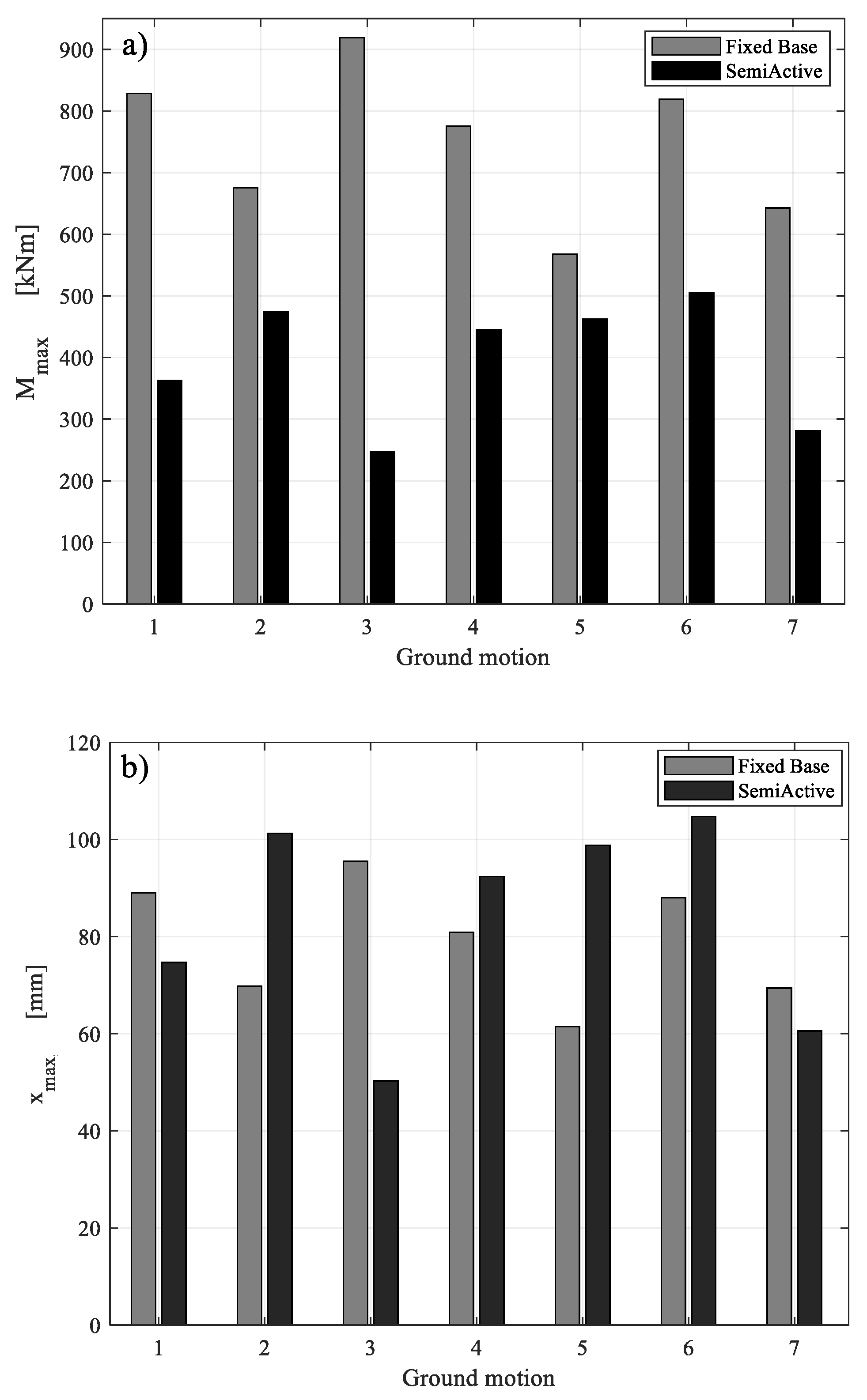
| GM | Mmax,FB | Mmax,SA | % | xmax,FB | xmax,SA | % |
|---|---|---|---|---|---|---|
| - | [kNm] | [kNm] | - | [mm] | [mm] | - |
| 1 | 829 | 363 | −56 | 90 | 70 | −16 |
| 2 | 675 | 474 | −30 | 70 | 100 | 31 |
| 3 | 919 | 247 | −73 | 95 | 50 | −47 |
| 4 | 775 | 445 | −43 | 81 | 90 | 11 |
| 5 | 567 | 462 | −19 | 62 | 98 | 32 |
| 6 | 819 | 505 | −38 | 88 | 104 | 16 |
| 7 | 643 | 281 | −56 | 70 | 60 | −13 |
Publisher’s Note: MDPI stays neutral with regard to jurisdictional claims in published maps and institutional affiliations. |
© 2022 by the authors. Licensee MDPI, Basel, Switzerland. This article is an open access article distributed under the terms and conditions of the Creative Commons Attribution (CC BY) license (https://creativecommons.org/licenses/by/4.0/).
Share and Cite
Caterino, N.; Spizzuoco, M.; Piccolo, V.; Magliulo, G. A Semi-Active Control Technique through MR Fluid Dampers for Seismic Protection of Single-Story RC Precast Buildings. Materials 2022, 15, 759. https://doi.org/10.3390/ma15030759
Caterino N, Spizzuoco M, Piccolo V, Magliulo G. A Semi-Active Control Technique through MR Fluid Dampers for Seismic Protection of Single-Story RC Precast Buildings. Materials. 2022; 15(3):759. https://doi.org/10.3390/ma15030759
Chicago/Turabian StyleCaterino, Nicola, Mariacristina Spizzuoco, Valeria Piccolo, and Gennaro Magliulo. 2022. "A Semi-Active Control Technique through MR Fluid Dampers for Seismic Protection of Single-Story RC Precast Buildings" Materials 15, no. 3: 759. https://doi.org/10.3390/ma15030759