
A Study on the Influential Factors of Stress Corrosion Cracking in C110 Casing Pipe


Abstract
:1. Introduction
2. Experiments
2.1. Materials
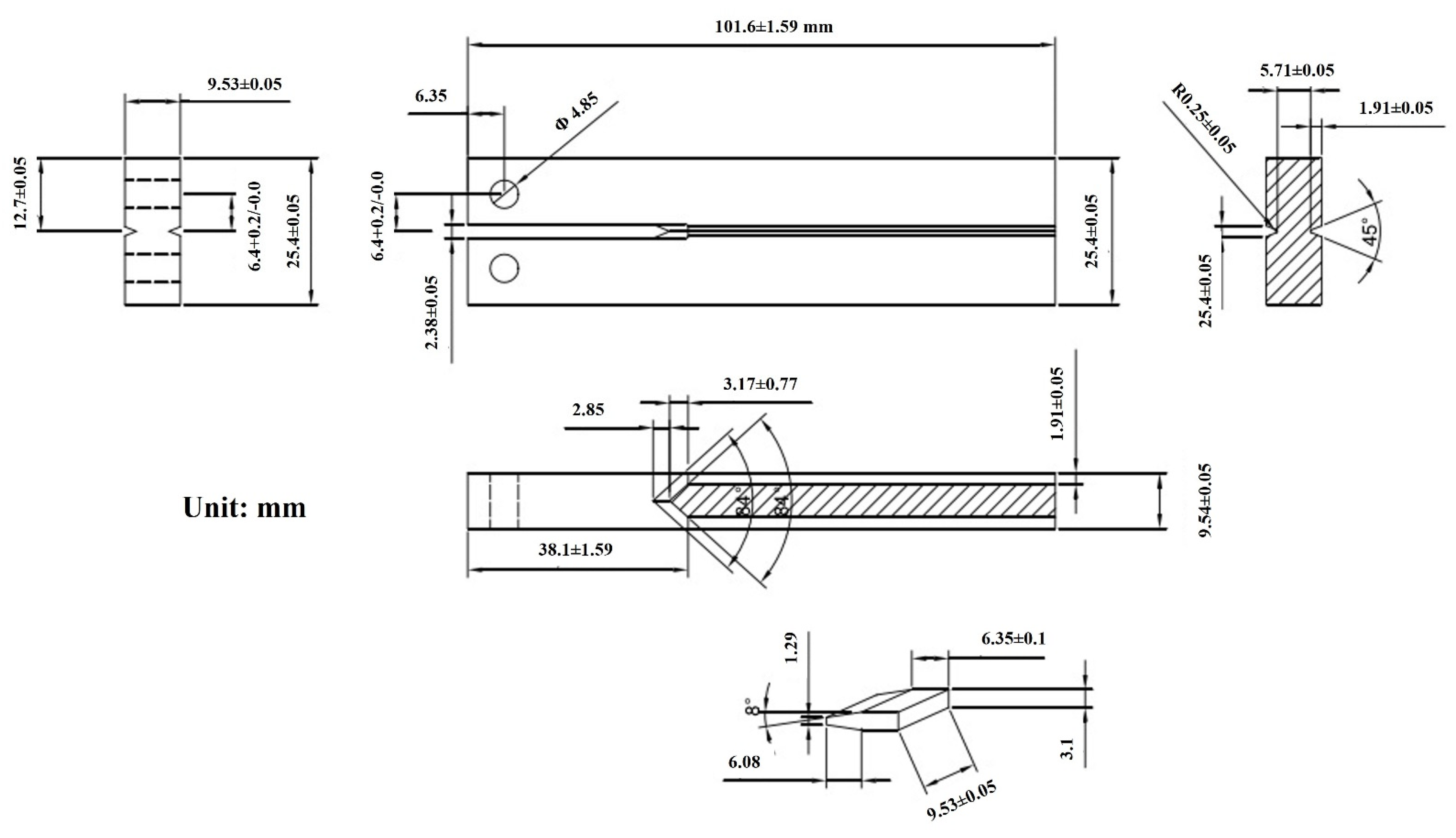
2.2. DCB Experiments
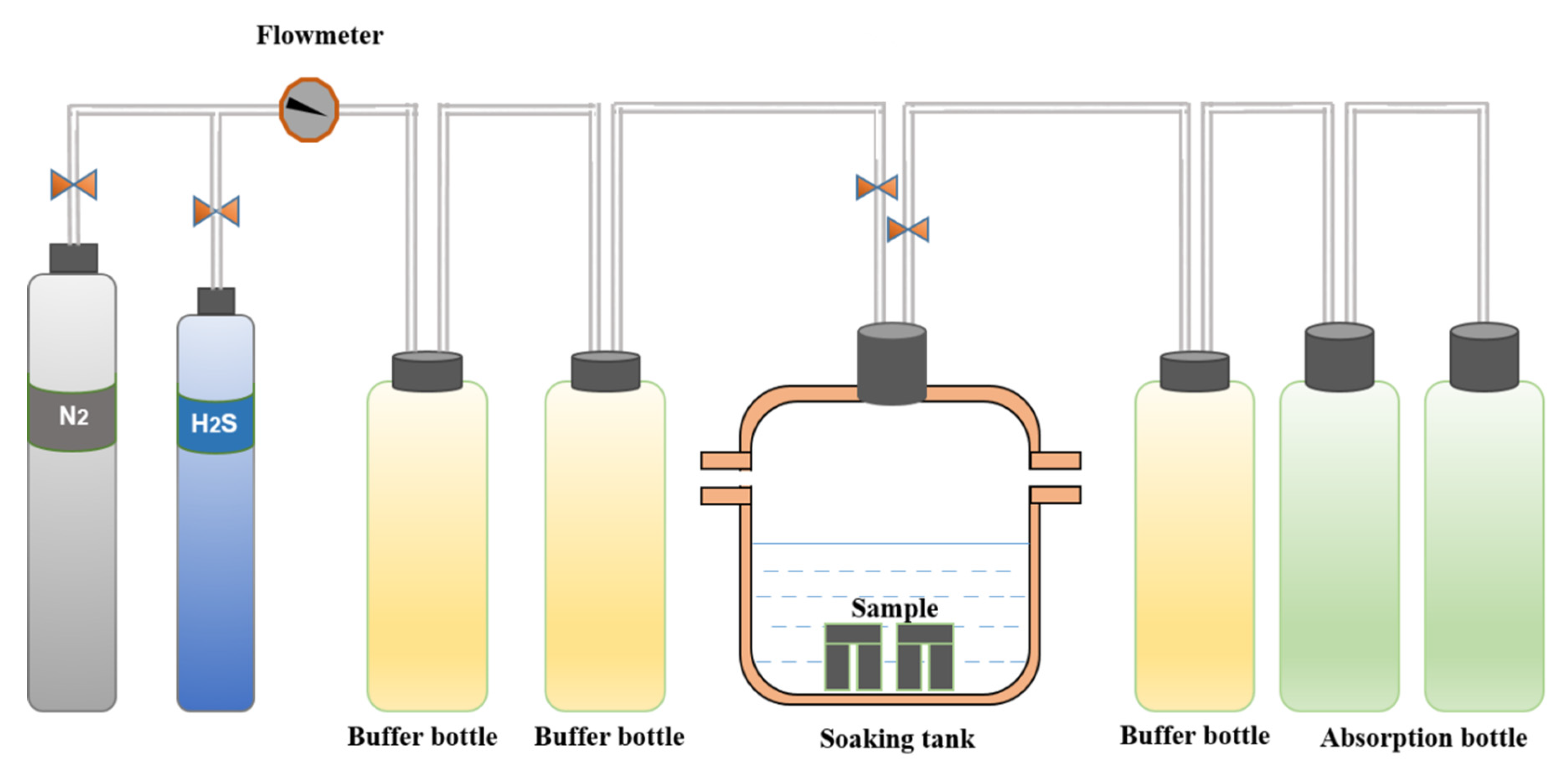
2.2.1. Experimental Equipment
2.2.2. Experimental Process
2.2.3. Fracture Morphology and Microstructure Analysis
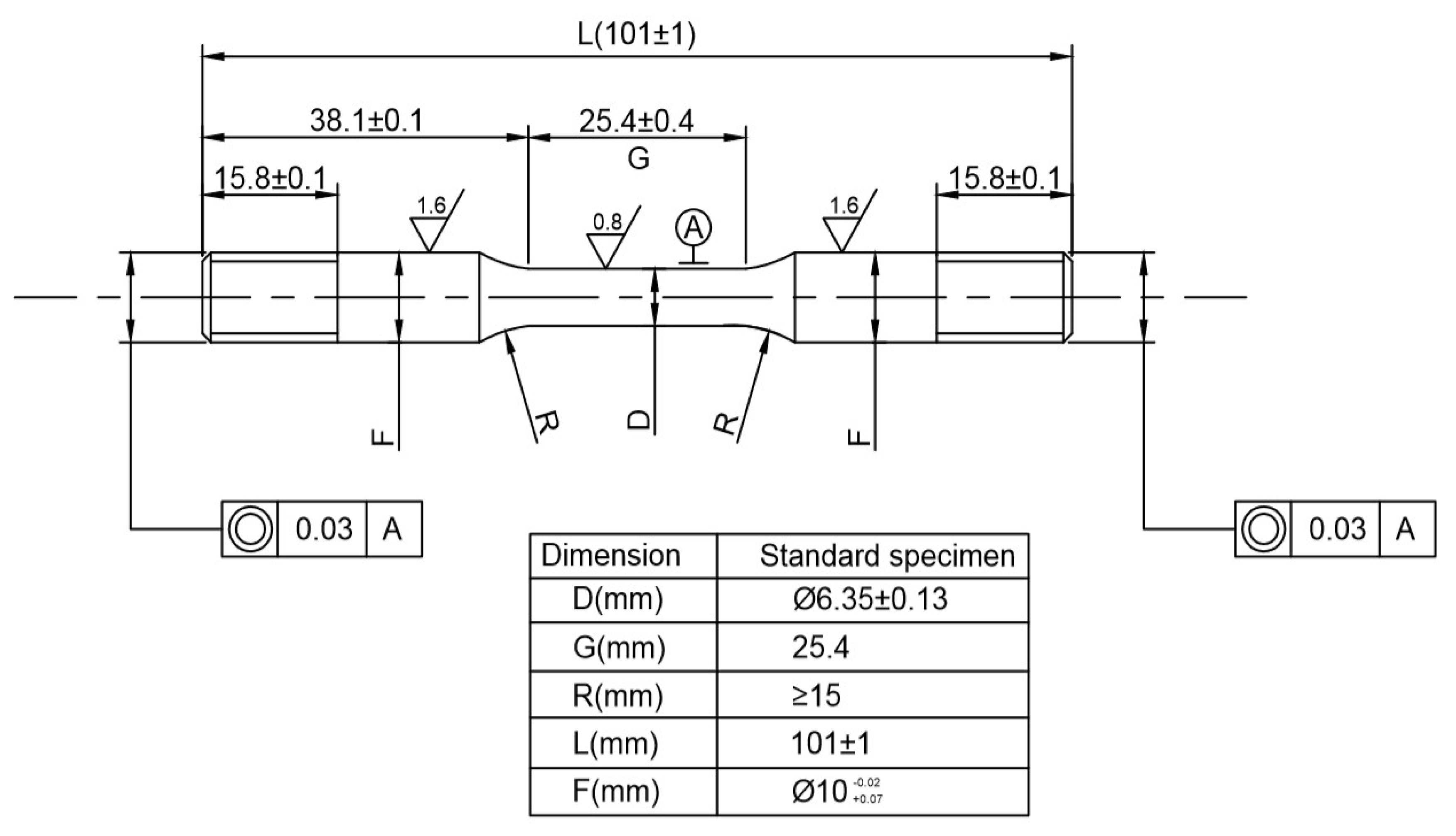
2.3. Constant-Load Experiment
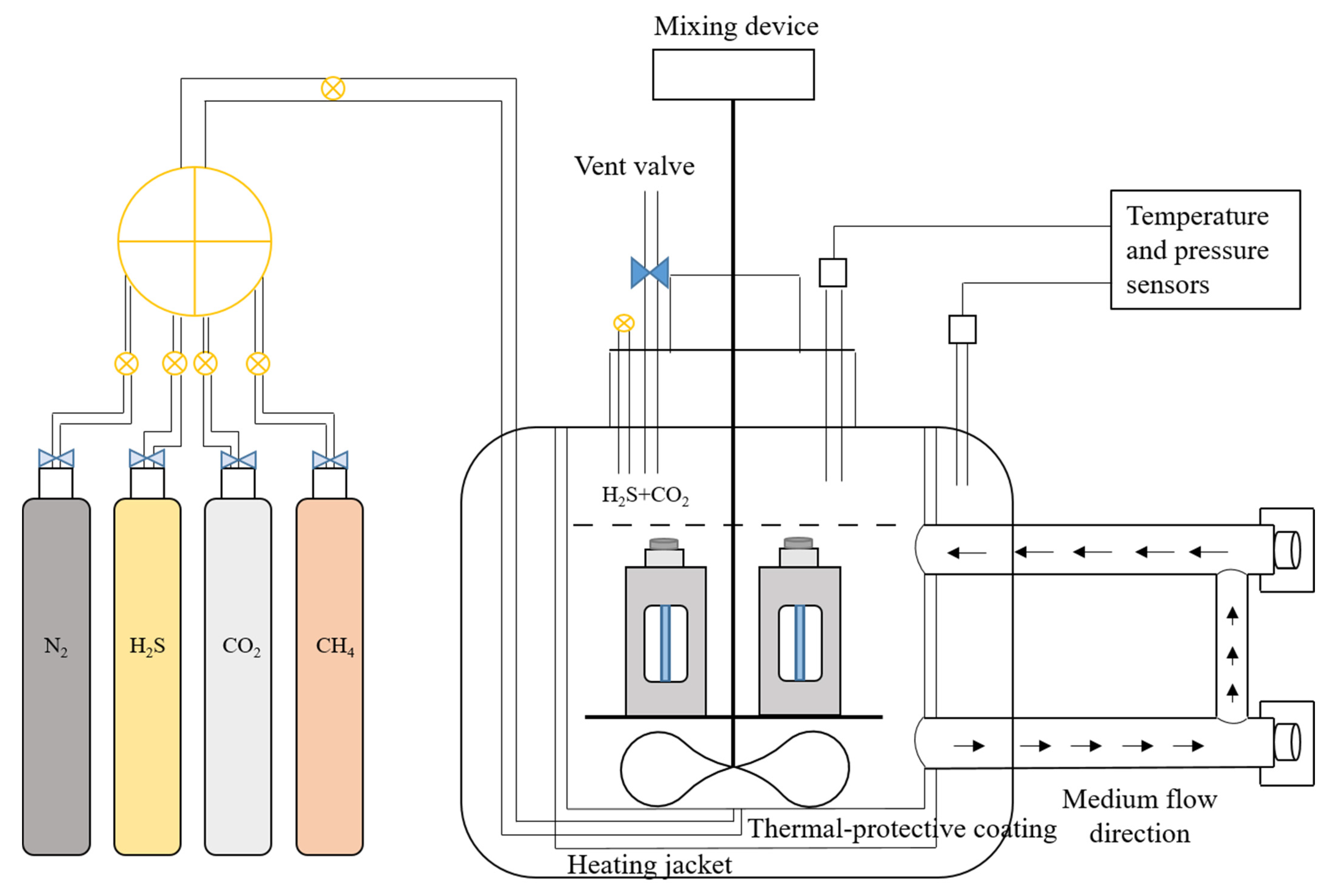
2.3.1. Experimental Equipment
2.3.2. Experimental Process
2.3.3. Mechanical Property Testing
2.3.4. Fracture Morphology and Surface Damage
3. Results and Discussion
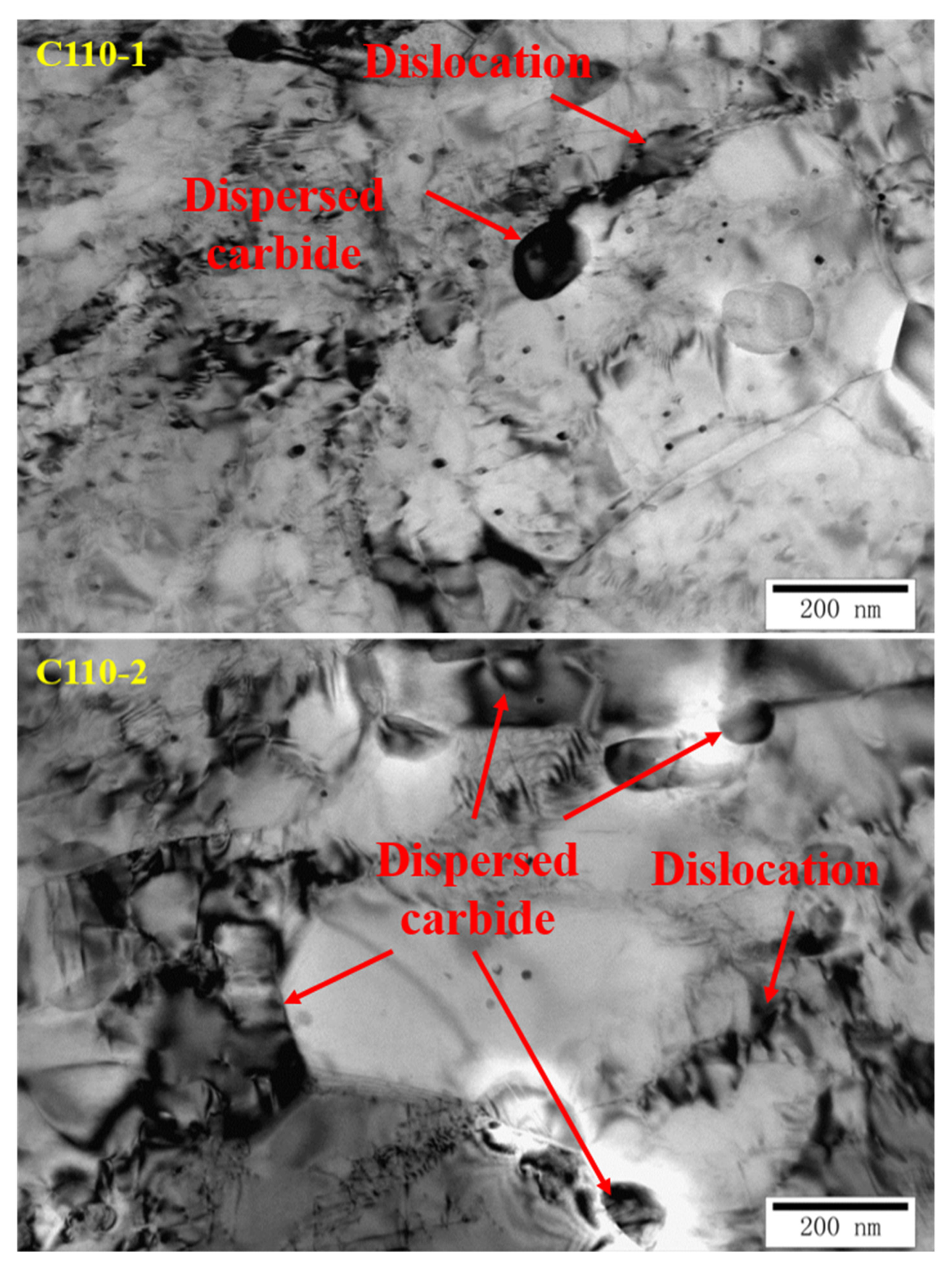
3.1. Analysis of Metallographic Structure, Microstructure, and Submicroscopic Structure
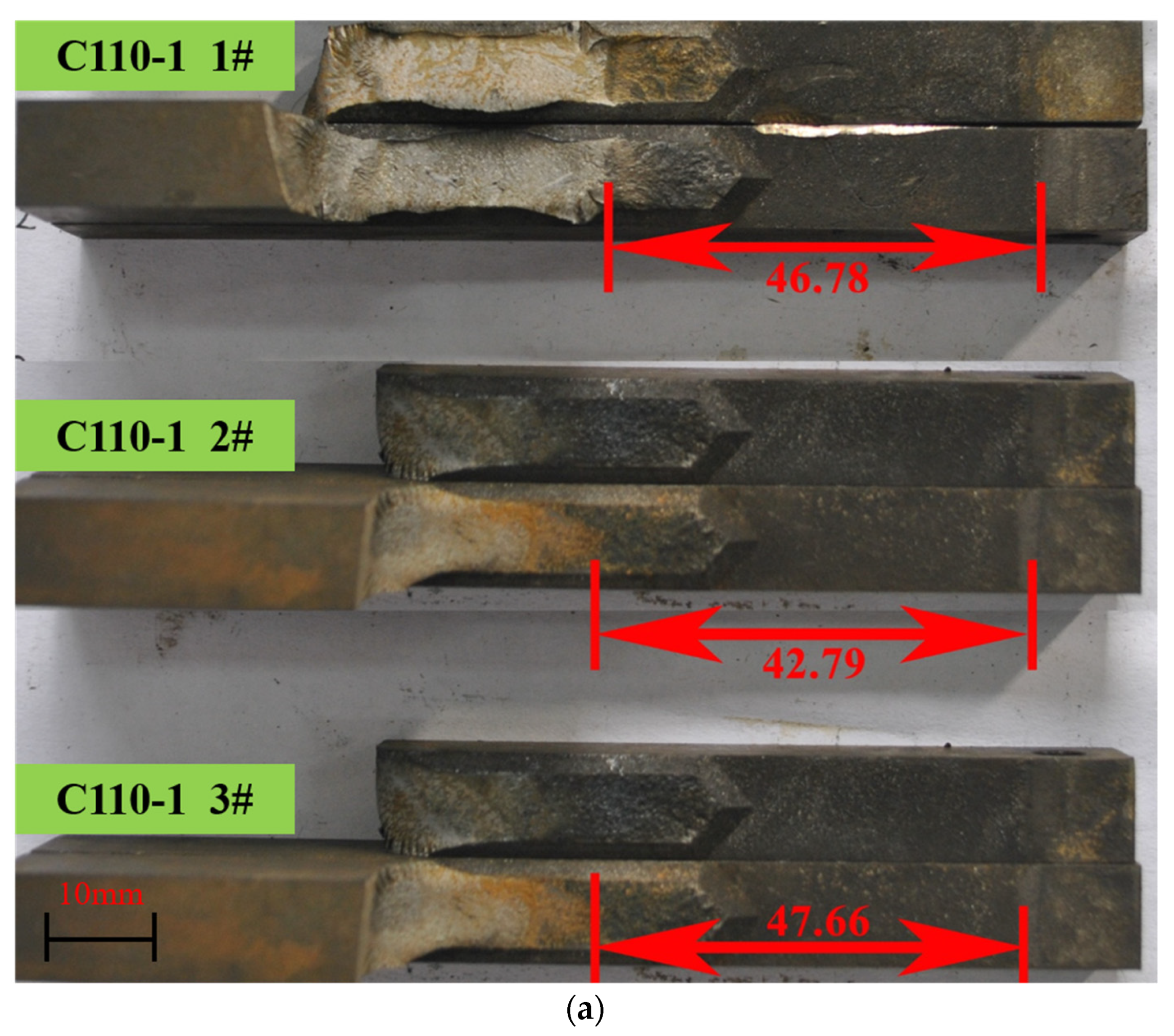
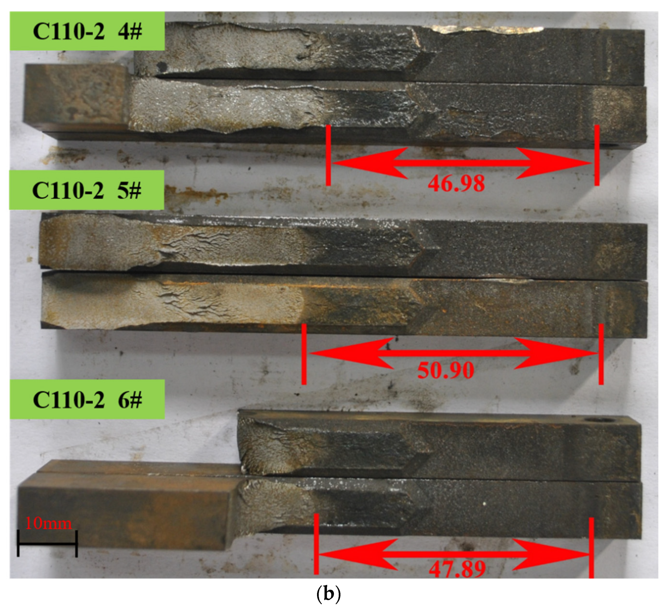
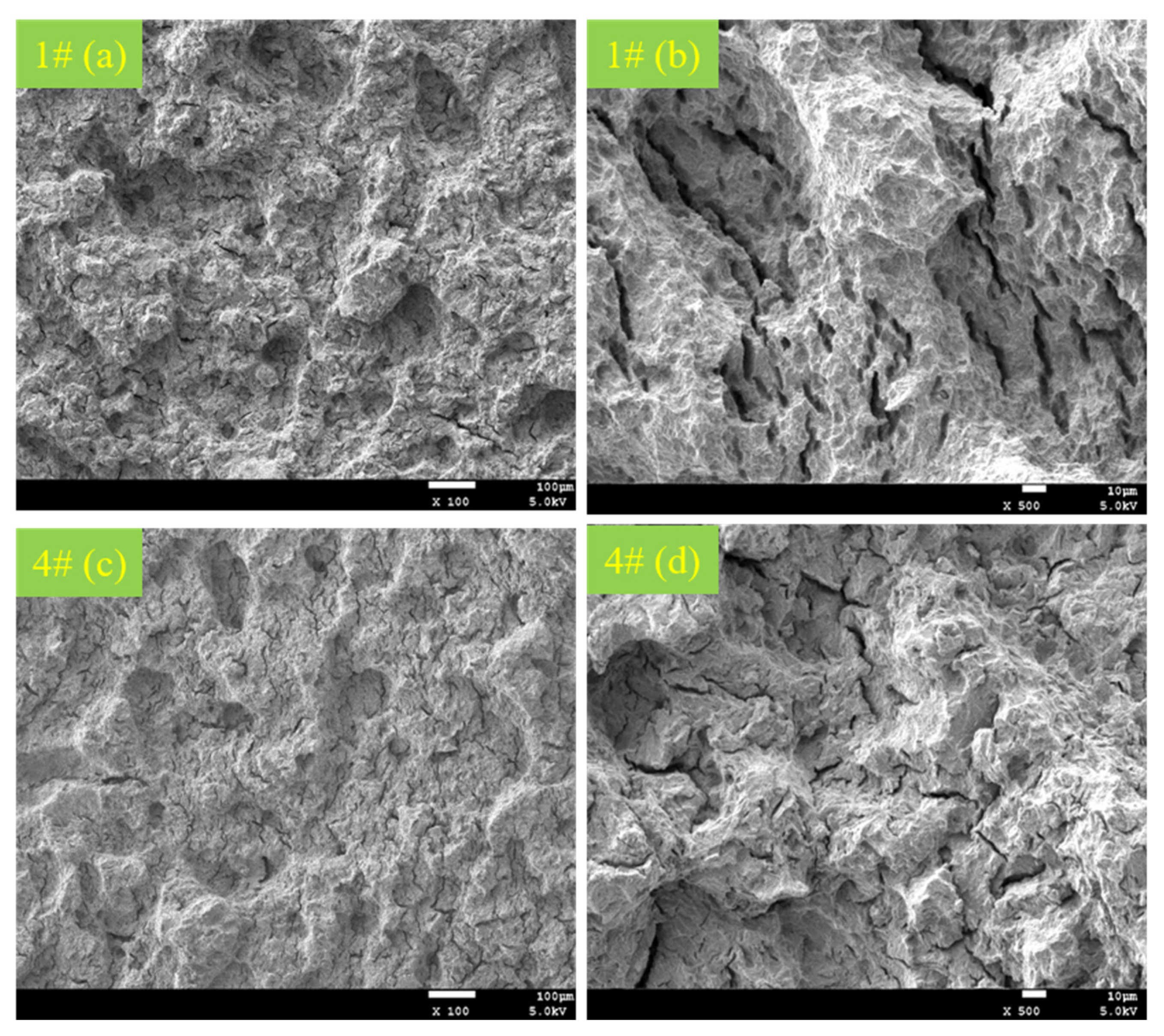
3.2. Analysis of KISSC and Fracture Morphology in the DCB Experiment
3.3. Analysis of Stress Damage
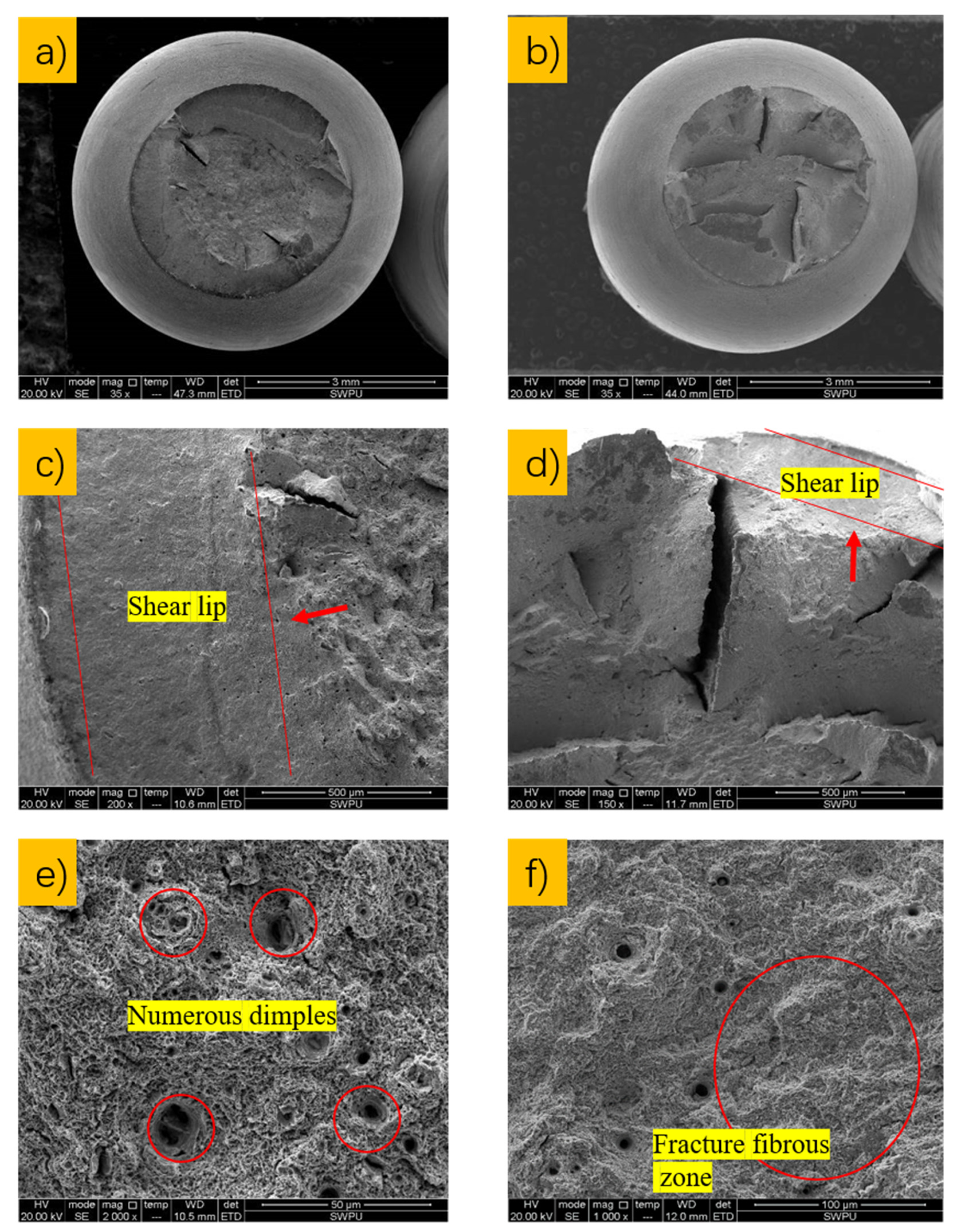
3.4. Analysis of Fracture Morphology
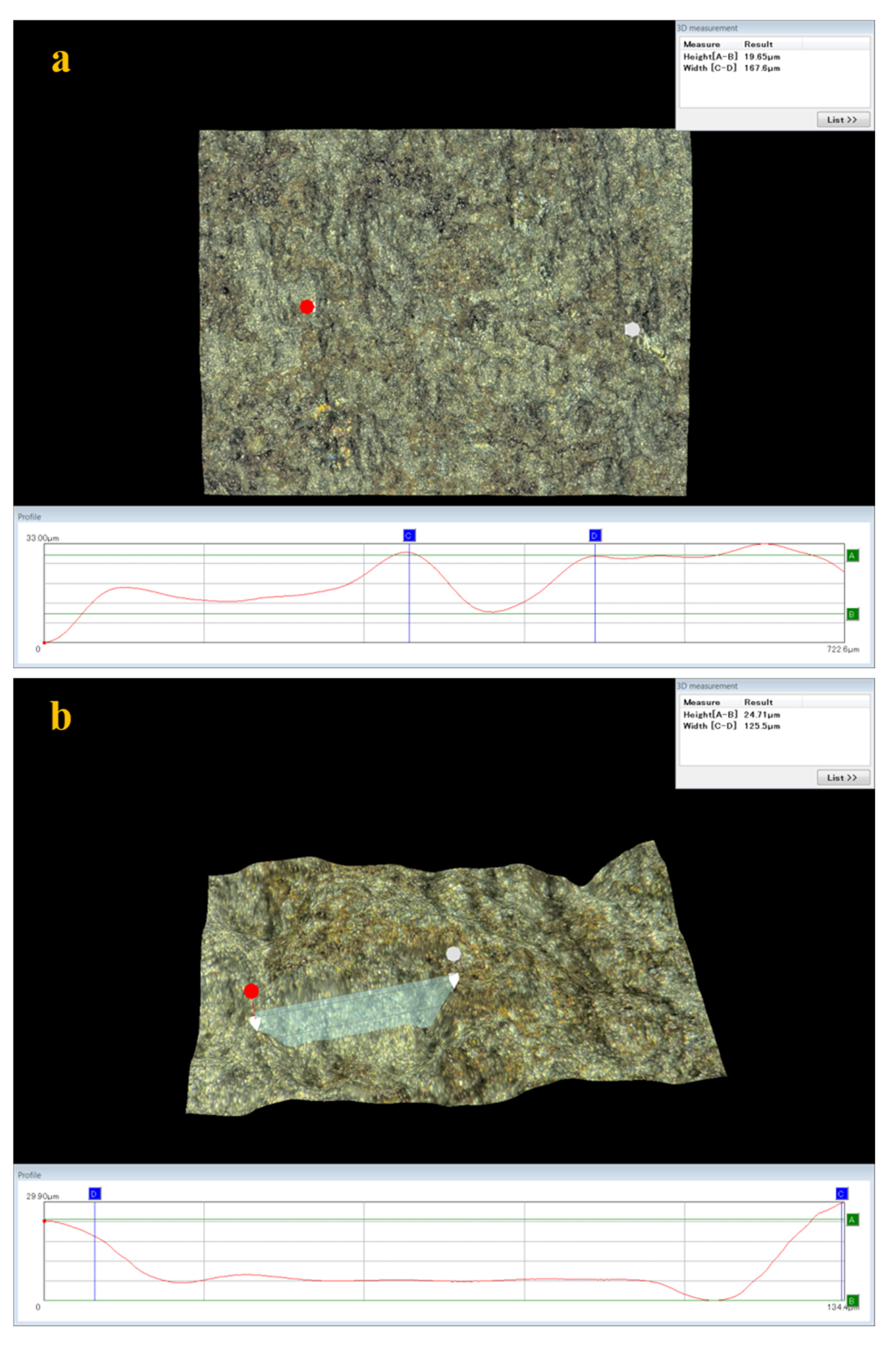
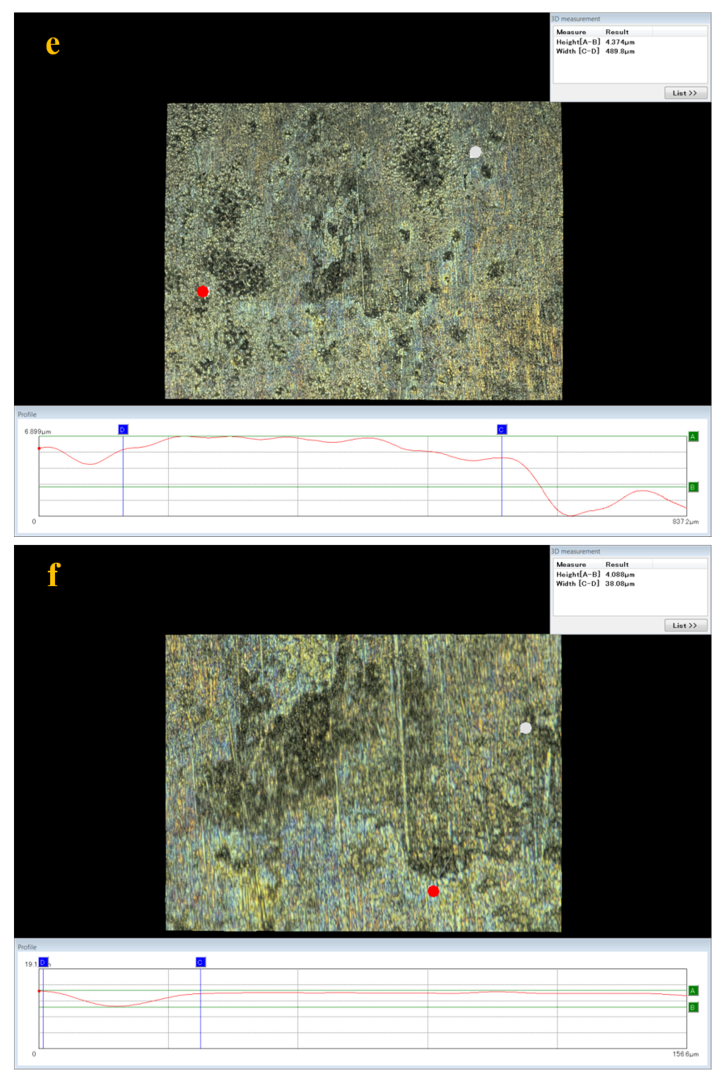
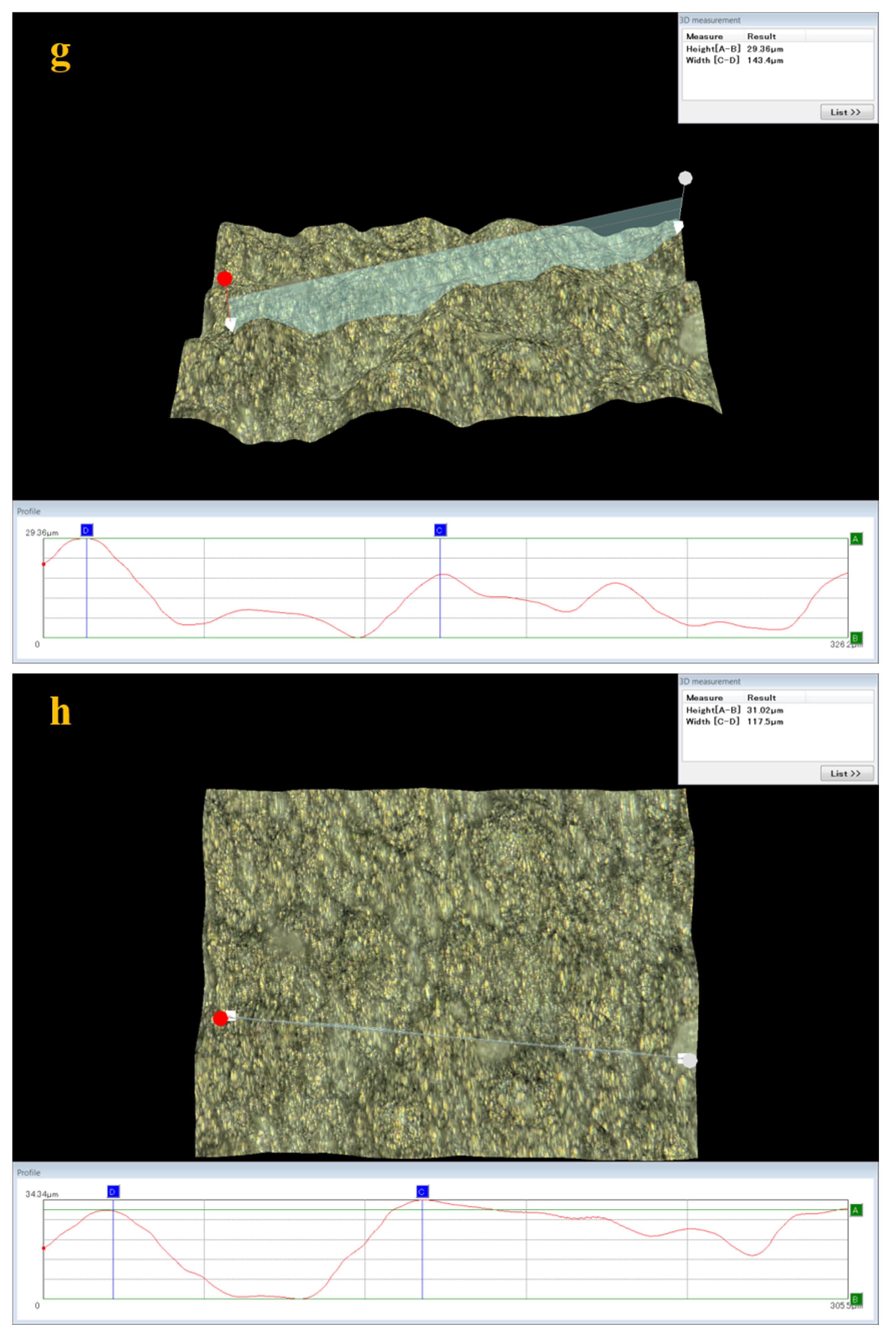
3.5. Analysis of Surface Damage
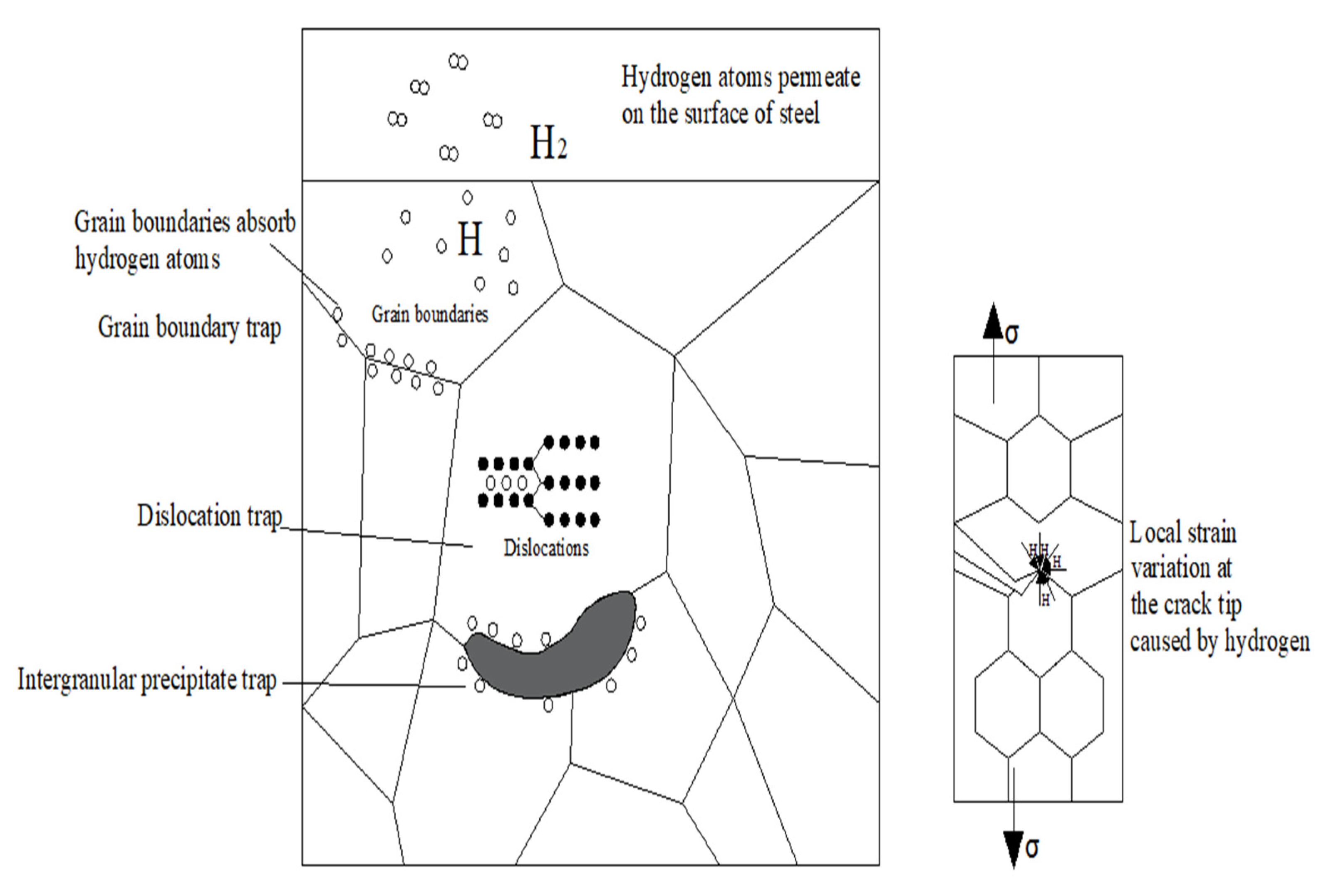
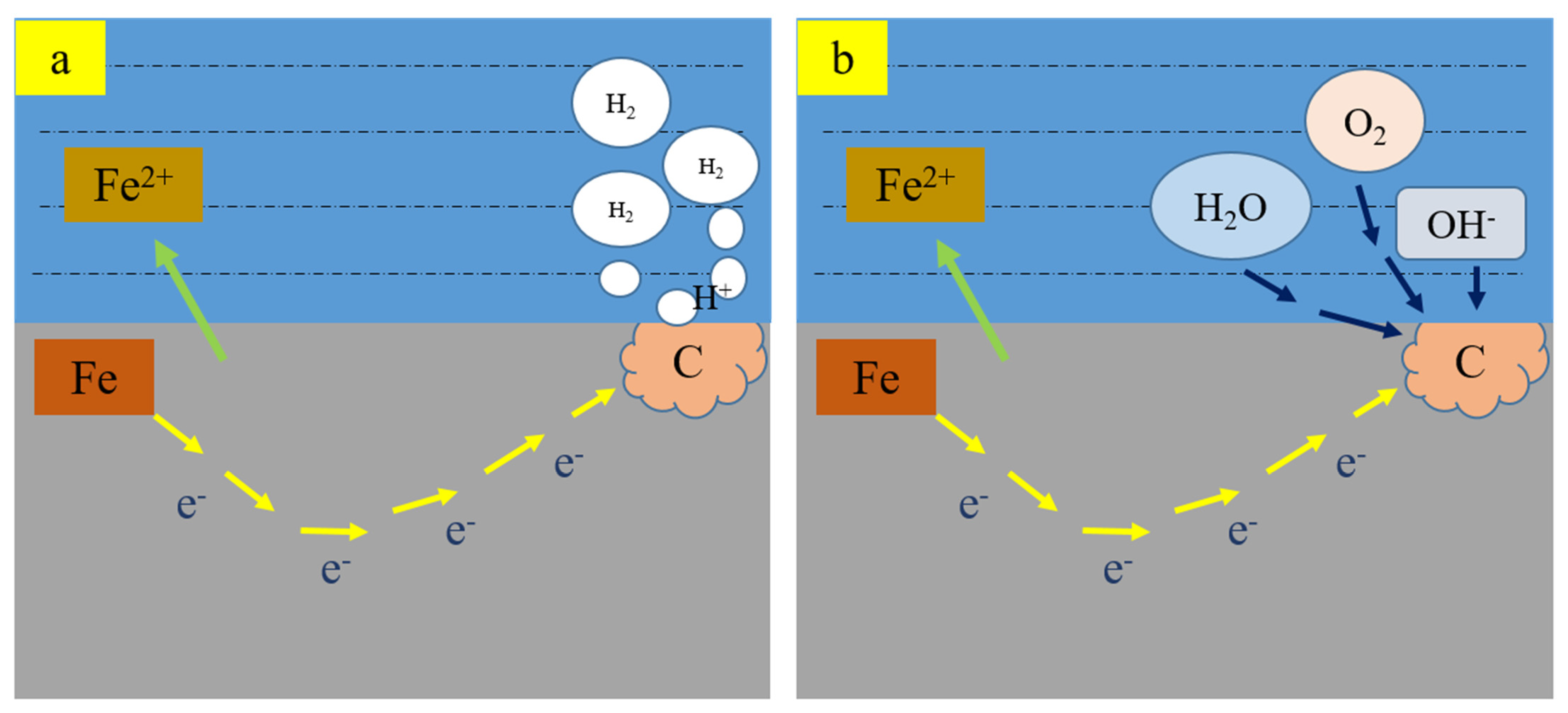
3.6. Effect of Hydrogen on Stress Corrosive Cracking
4. Conclusions
- (1)
- Both C110-1 and C110-2 casing pipe materials meet the requirements of the ISO 11960 standard, but after the tests in DCB standard A solution, the two materials suffered a certain level of stress corrosion cracking and generated cracks. Therefore, it is essential to evaluate the environmental cracking applicability of these two C110 casing pipes by the high-temperature, high-pressure, constant-load method under circumstances simulating the actual working conditions.
- (2)
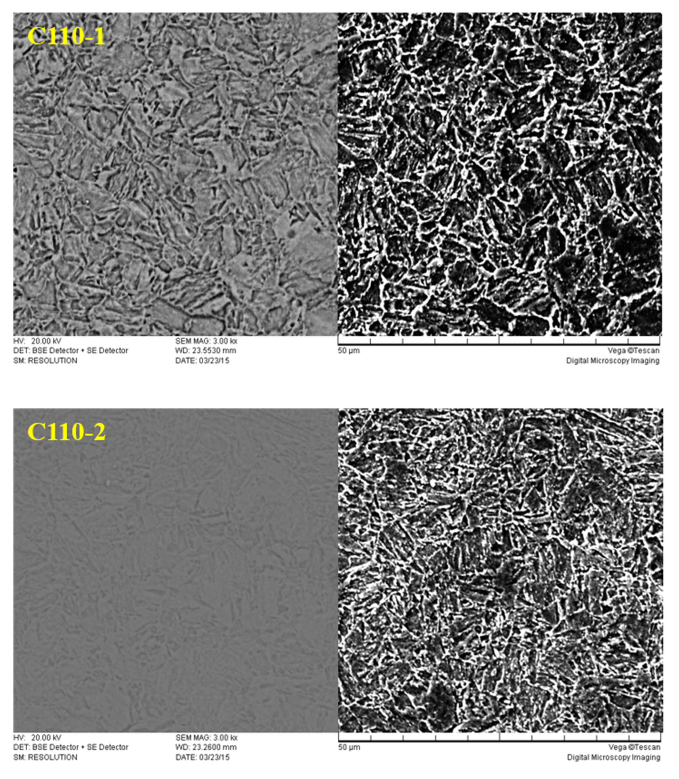
- The carbides dispersed in the microstructure exist in the matrix in the form of hydrogen traps, providing many vacancies for the redistribution of infiltrated hydrogen atoms, which can effectively hinder the microregional hydrogen embrittlement caused by high hydrogen pressure in partial regions; this weakens the increase in the partial hydrogen concentration caused by the fusion of infiltrated hydrogen and strong hydrogen-traps in the material, and as a result, the possibility of crack generation is also reduced. Besides this, the dispersed carbide can improve the SSC resistance of the material as well.
- (3)
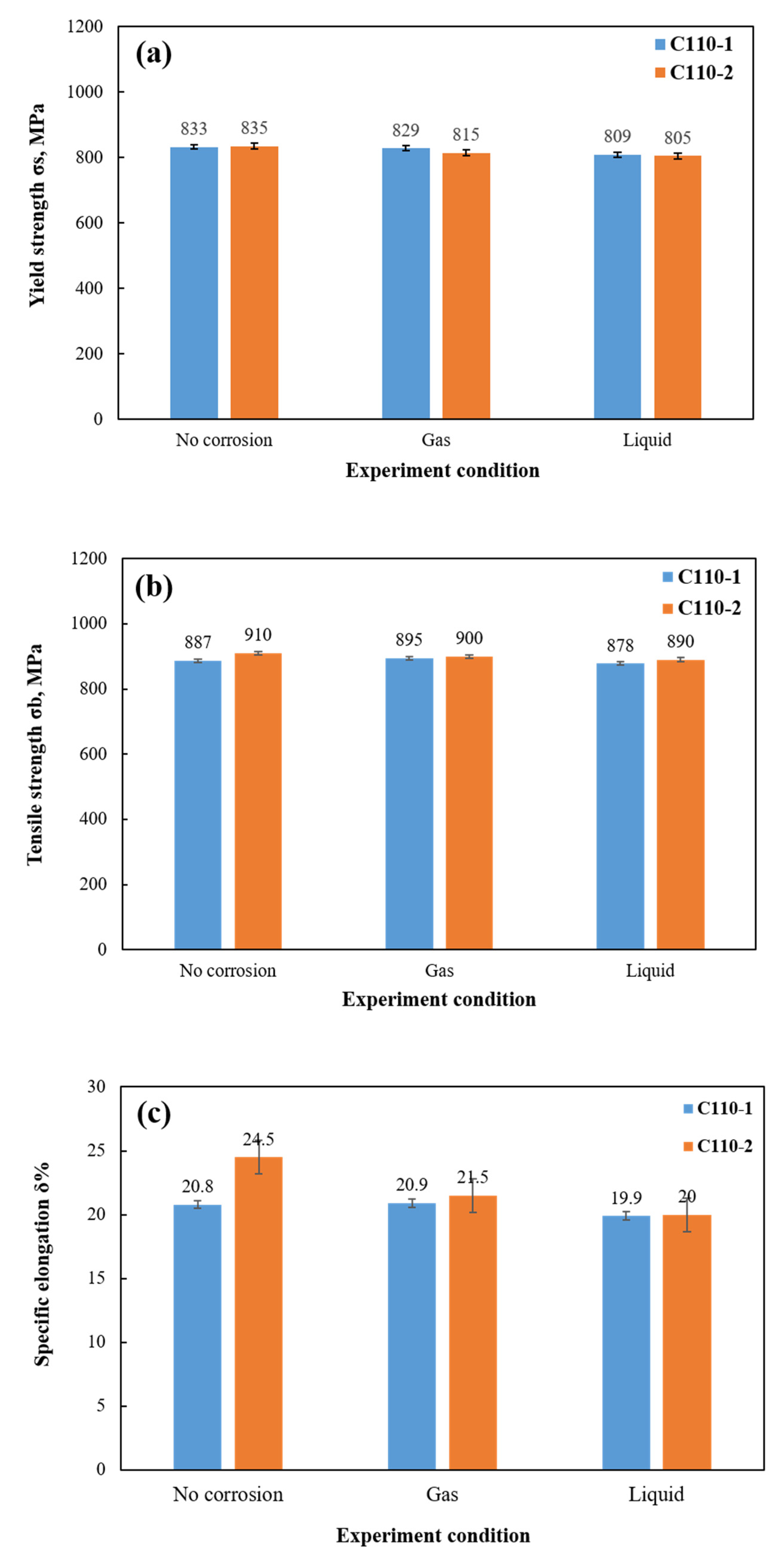
- After stress corrosion cracking tests with constant load under high temperature and high pressure, both materials suffered a certain degree of stress damage. Between the two of them, the mechanical properties of C110-2 after corrosion were slightly better than those of C110-1.
- (4)
- Through analysis of the tensile fracture, it was observed that C110-2 has stronger resistance to environmental cracking under stress corrosion circumstances and is able to maintain high ductility even after stress corrosion.
- (5)
- Under the action of stress, the infiltration of H into the metal material is accelerated, expediting crack propagation and lowering the KISSC value.
Author Contributions
Funding
Institutional Review Board Statement
Informed Consent Statement
Conflicts of Interest
References
- Wang, C.L. The present situation and prospect of world oil and gas industry. Sinopec 2007, 9, 3. (In Chinese) [Google Scholar]
- Pessu, F.; Hua, Y.; Barker, R.; Neville, A. A Study of the Pitting and Uniform Corrosion Characteristics of X65 Carbon Steel in Different H2S-CO2-Containing Environments. Corros. J. Sci. Eng. 2018, 74, 886–902. [Google Scholar] [CrossRef]
- Zeng, D.Z.; He, Q.Y.; Yu, Z.M.; Jia, W.Y.; Zhang, S.; Liu, Q.P. Risk assessment of sustained casing pressure in gas wells based on the fuzzy comprehensive evaluation method. J. Nat. Gas Sci. Eng. 2017, 46, 756–763. [Google Scholar] [CrossRef]
- Zhou, P.; Liang, J.M.; Zhang, F.; Wu, H.B.; Tang, D. Influence of Chromium on Corrosion Behavior of Low-alloy Steel in Cargo Oil Tank O2-CO2-SO2-H2S Wet Gas Environment. J. Iron Steel Res. Int. 2015, 22, 630–637. [Google Scholar] [CrossRef]
- Hu, L.H.; Chang, W.; Zhang, L.; Li, Z.T.; Yu, T.; Xu, L.N.; Lu, M.X. Research on the CO2 corrosion resistance of X65 and 3Cr steels applied to subsea pipeline. China Off Shore Oil Gas 2011, 23, 131–134. (In Chinese) [Google Scholar]
- Zhang, Z.H.; Huang, Z.Y.; Sun, Y.N.; Cai, H.Y.; Guo, J.B. Development of 3Cr Series Oil Pipes with Good CO2 and H2S Corrosion resistant Properties. Bao Steel Technol. 2006, 3, 5–8. (In Chinese) [Google Scholar]
- Loffe, A.V.; Tetyueva, T.V.; Revyakin, V.A.; Borisenkova, E.A.; Knyaz’kin, S.A.; Denisova, T.V. Corrosion-mechanical fracture of tube steels in operation. Met. Sci. Heat Treat. 2013, 54, 512–518. [Google Scholar]
- Wei, L.; Pang, X.L.; Gao, K.W. Effect of small amount of H2S on the corrosion behavior of carbon steel in the dynamic supercritical CO2 environments. Corros. Sci. J. Environ. Degrad. Mater. Its Control. 2016, 103, 132–144. [Google Scholar]
- Choi, Y.S.; Hassani, S.; Vu, T.N.; Nešić, S.; Abas, A.Z.B. Effect of H2S on the Corrosion Behavior of Pipeline Steels in Supercritical and Liquid CO2 Environments. Corrosion 2016, 72, 999–1009. [Google Scholar] [CrossRef]
- Choi, Y.S.; Nesic, S.; Ling, S. Effect of H2S on the CO2 corrosion of carbon steel in acidic solutions. Electrochim. Acta 2011, 56, 1752–1760. [Google Scholar] [CrossRef]
- Elgaddafi, R.; Ahmed, R.; Shah, S. Modeling and experimental studies on CO2-H2S corrosion of API carbon steels under high-pressure. J. Pet. Eng. 2017, 156, 682–696. [Google Scholar] [CrossRef]
- Zhang, N.Y.; Zeng, D.Z.; Xiao, G.Q.; Shang, J.F.; Liu, Y.Z. Effect of Cl accumulation on corrosion behavior of steels in H2S-CO2 methyldiethanolamine (MDEA) gas sweetening aqueous solution. J. Nat. Gas Sci. Eng. 2016, 30, 444–454. [Google Scholar] [CrossRef]
- Petrov, A.I.; Razuvaeva, M.V. Stress Corrosion Cracking of Metals and Alloys in Aggressive H2S-CO2-Cl–Environments. Tech. Phys. 2019, 64, 1814–1820. [Google Scholar] [CrossRef]
- Shi, F.X.; Zhang, L.; Yang, J.W.; Lu, M.X.; Ding, J.H.; Li, H. Polymorphous FeS corrosion products of pipeline steel under highly sour conditions. Corros. Sci. 2015, 102, 103–113. [Google Scholar]
- Henthorne, M. The Slow Strain Rate Stress Corrosion Cracking Test-A 50 Year Retrospective. Corros. J. Sci. Eng. 2016, 72, 1488–1518. [Google Scholar] [CrossRef]
- Wen, X.; Bai, P.; Luo, B.; Zheng, S.; Chen, C. Review of recent progress in the study of corrosion products of steels in a hydrogen sulphide environment. Corros. Sci. 2018, 139, 124–140. [Google Scholar] [CrossRef]
- Wang, Y.F. Corrosion rule of P110SS under high H2S and CO2 conditions. Fault-Block Oil Gas Field 2017, 24, 4. (In Chinese) [Google Scholar]
- Zhao, X.Y.; Ye, F.; Tang, S. Cause of Corrosion and Perforation of P110 Tubing in an Oil Well. Mater. Mech. Eng. 2020, 44, 5. (In Chinese) [Google Scholar]
- Zhao, X.W.; Huang, W.; Li, G.; Feng, Y.; Zhang, J. Effect of CO2-H2S and Applied Stress on Corrosion Behavior of 15Cr Tubing in Oil Field Environment. Met. Open Access Metall. J. 2020, 10, 409. [Google Scholar] [CrossRef] [Green Version]
- Zhang, Z.; Zheng, Y.; Li, J.; Liu, W.; Liu, M.; Gao, W.; Shi, T. Stress corrosion crack evaluation of super 13Cr tubing in high-temperature and high-pressure gas wells. Eng. Fail. Anal. 2019, 95, 263–272. [Google Scholar] [CrossRef]
- Qiu, Z.C.; Liu, X.; Zhang, N. Corrosion Behavior of 13Cr Steel in Different Temperature. Adv. Mater. Res. 2014, 937, 168–171. [Google Scholar] [CrossRef]
- Xue, Y.; Zhao, M.; Xiang, H.L.; Xie, J.; Zhao, G.; Li, D.P. Stress Corrosion Cracking Evaluation Methods of Stainless Steel Tubing. Corros. Prot. 2018, 13, 6309–6396. (In Chinese) [Google Scholar]
- Lian, Z.H.; Liang, Z.K.; Wang, Y.H.; Zhang, Q.; Mou, Y.S. Equation Derivation and Verification for Hoop Stress and Load of C-ring. J. Southwest Pet. Univ. 2019, 45, 161. (In Chinese) [Google Scholar]
- Zhu, S.D.; Wei, J.F.; Cai, R.; Bai, Z.Q.; Zhou, G.S. Corrosion failure analysis of high strength grade super 13Cr-110 tubing string. Eng. Fail. Anal. 2011, 18, 2222–2231. [Google Scholar] [CrossRef]
- Lei, X.W.; Feng, Y.R.; Fu, A.Q.; Zhang, J.X.; Bai, Z.Q.; Yin, C.X.; Lu, C.H. Investigation of stress corrosion cracking behavior of super 13Cr tubing by full-scale tubular goods corrosion test system. Eng. Fail. Anal. 2015, 50, 62–70. [Google Scholar] [CrossRef]
- Deng, X.Y.; Wang, X.M.; Duan, B.M.; Li, L.X. Failure Analysis of Sulfide Stress Corrosion for Oil Casing. Hot Work. Technol. 2018, 47, 4. (In Chinese) [Google Scholar]
- Szklarz, K.E. KLIMIT in NACE TM0177—Method D (DCB): Definition, measurement and use. In Proceedings of the CORROSION 2011, Houston, TX, USA, 13–17 March 2011. [Google Scholar]
- Hou, D.; Zeng, D.Z.; Shi, T.H.; Deng, W.L. Evaluation Method of Tubing and Casing EIC in High Temperature and High Pressure Sour Environment. Corros. Sci. Prot. Technol. 2013, 25, 317–321. [Google Scholar]
- Lin, J.; Chen, F.; Liu, F.; Xu, D.; Tang, X. Hydrogen permeation behavior and hydrogen-induced defects in 316L stainless steels manufactured by additive manufacturing. Mater. Chem. Phys. 2020, 250, 123038. [Google Scholar] [CrossRef]
- Asari, D.; Mizokami, S.; Fukahori, M.; Takai, K. Microscopic defects formed during crack incubation, initiation and propagation processes causing hydrogen-related fracture of dual-phase steels. Mater. Sci. Eng. A 2020, 780, 139209. [Google Scholar] [CrossRef]
- Niu, Y.L.; Liu, Y.S.; Liu, Q.Y.; Jia, S.J.; Tong, S.; Wang, B. Low temperature toughness of acicular ferrite pipeline steel and redefinition of “effective grain size”. Heat Treat. Met. 2020, 45, 101–110. (In Chinese) [Google Scholar]
- Park, K.T.; Si, W.H.; Ji, J.H.; Chang, H.L. Inclusions nucleating intragranular polygonal ferrite and acicular ferrite in low alloyed carbon manganese steel welds. Met. Mater. Int. 2011, 17, 349–356. [Google Scholar] [CrossRef]
- Zhang, H.; Li, S.B.; Ding, W.H.; Hao, N. Effects of microstructure and crystallographic texture on anisotropy of tensile strength of X80 pipeline steel. Heat Treat. Met. 2018, 43, 4. (In Chinese) [Google Scholar]
- Yang, J.; Li, C.F.; Shen, W.Z. Research status and application prospect of formation of acicular ferrite. Heat Treat. Met. 2013, 38, 5. [Google Scholar]
- Toppo, A.; Pujar, M.G.; Sreevidya, N.; Philip, J. Pitting and stress corrosion cracking studies on AISI type 316N stainless steel weldments. Def. Technol. 2018, 14, 12. [Google Scholar] [CrossRef]
- Xiang, L.; Pan, J.; Chen, S. Analysis on the stress corrosion crack inception based on pit shape and size of the FV520B tensile specimen. Results Phys. 2018, 9, 463–470. [Google Scholar] [CrossRef]
- TDS, A.; LV, A.; Td, A.; ARDV, B.; KV, A. Mechanical degradation of Fe-C-X steels by acidic stress-corrosion cracking—Science Direct. Corros. Sci. 2020, 167, 108509. [Google Scholar]
- Li, S.Y.; Hu, R.S.; Zhao, W.M.; Li, B.B.; Wang, Y. Hydrogen Adsorption and Diffusion on Steel Surface. Surf. Technol. 2020, 49, 7. (In Chinese) [Google Scholar]


| Steel | C | Si | Mn | P | S | Ni | Cr | Cu | Ti | Nb | Mo | V |
|---|---|---|---|---|---|---|---|---|---|---|---|---|
| C110-1 | 0.25 | 0.21 | 0.50 | 0.007 | 0.001 | 0.03 | 0.54 | 0.03 | 0.05 | 0.04 | 0.65 | 0.11 |
| C110-2 | 0.27 | 0.27 | 0.51 | 0.008 | 0.001 | 0.03 | 1.09 | 0.01 | 0.02 | 0.04 | 0.56 | 0.10 |
| ISO C110 | Max 0.35 | - | Max 1.2 | Max 0.020 | Max 0.003 | Max 0.99 | 0.4–1.5 | - | - | - | 0.25–1.0 | - |
| Steel | Yield Strength, MPa | Tensile Strength, MPa | Elastic Modulus, GPa | Yield Ratio | Elongation after Fracture, % |
|---|---|---|---|---|---|
| C110-1 | 833 (120 ksi) | 887 (128 ksi) | 210 | 0.94 | 20.8 |
| C110-2 | 837 (121 ksi) | 908 (131 ksi) | 220 | 0.92 | 24.5 |
| Level (A) | Yield Strength Range | Approved Cantilever Displacement (δ) |
|---|---|---|
| MPa | mm | |
| L-80 | 552–655 | 0.71–0.97 |
| C-90 | 621–724 | 0.64–0.89 |
| C-95,T-95 | 655–758 | 0.58–0.84 |
| Level 100 | 689–793 | 0.51–0.76 |
| Level 105 | 724–827 | 0.46–0.71 |
| Level 110 | 758–862 | 0.38–0.64 |
| P-110 | 758–965 | 0.25–0.64 |
| Q-125 | 862–1030 | 0.25–0.51 |
| Main Content Types | Main Ion Content, g/L | Density, g/cm3 | pH Value | Total Salinity, g/L | ||||||
|---|---|---|---|---|---|---|---|---|---|---|
| Na+ | K+ | Ca2+ | Mg2+ | Cl− | SO42− | HCO3− | ||||
| Contents | 59.00 | 10.04 | 11.43 | 2.43 | 126.52 | 0.71 | 0.71 | 0.996 | 5.38 | 210.84 |
| Reagent Name | Molecular Weight, g/mol | Dosage, g/L |
|---|---|---|
| NaCl | 58.44 | 148.37 |
| KCl | 74.55 | 19.20 |
| MgCl2·6H2O | 203.20 | 20.35 |
| CaCl2 | 110.98 | 31.70 |
| NaHCO3 | 83.99 | 0.98 |
| Na2SO4 | 142.04 | 1.05 |
| Number | Material | P, N | a, mm | h, mm | B, mm | Bn, mm | KISSC, MPa∙m1/2 | |
|---|---|---|---|---|---|---|---|---|
| Tested | Average | |||||||
| 1 | C110-1 | 1510 | 46.78 | 12.70 | 9.51 | 6.25 | 27.18 | 27.16 |
| 2 | 1660 | 42.79 | 12.70 | 9.53 | 6.25 | 27.71 | ||
| 3 | 1450 | 47.66 | 12.70 | 9.52 | 6.25 | 26.58 | ||
| 4 | C110-2 | 1510 | 46.98 | 12.70 | 9.52 | 6.25 | 27.27 | 28.19 |
| 5 | 1500 | 50.90 | 12.70 | 9.52 | 6.25 | 29.03 | ||
| 6 | 1540 | 47.89 | 12.70 | 9.51 | 6.25 | 28.28 | ||
Publisher’s Note: MDPI stays neutral with regard to jurisdictional claims in published maps and institutional affiliations. |
© 2022 by the authors. Licensee MDPI, Basel, Switzerland. This article is an open access article distributed under the terms and conditions of the Creative Commons Attribution (CC BY) license (https://creativecommons.org/licenses/by/4.0/).
Share and Cite
Wang, Z.; Wang, P.; Zeng, D.; Shi, T.; Deng, W. A Study on the Influential Factors of Stress Corrosion Cracking in C110 Casing Pipe. Materials 2022, 15, 801. https://doi.org/10.3390/ma15030801
Wang Z, Wang P, Zeng D, Shi T, Deng W. A Study on the Influential Factors of Stress Corrosion Cracking in C110 Casing Pipe. Materials. 2022; 15(3):801. https://doi.org/10.3390/ma15030801
Chicago/Turabian StyleWang, Zhe, Pingquan Wang, Dezhi Zeng, Taihe Shi, and Wenliang Deng. 2022. "A Study on the Influential Factors of Stress Corrosion Cracking in C110 Casing Pipe" Materials 15, no. 3: 801. https://doi.org/10.3390/ma15030801
APA StyleWang, Z., Wang, P., Zeng, D., Shi, T., & Deng, W. (2022). A Study on the Influential Factors of Stress Corrosion Cracking in C110 Casing Pipe. Materials, 15(3), 801. https://doi.org/10.3390/ma15030801