
Photocatalytic Reduction of Carbon Dioxide on TiO2 Heterojunction Photocatalysts—A Review


Abstract
:1. Introduction
2. TiO2 Heterojunction Photocatalysts
2.1. g-C3N4/TiO2
2.2. CeO2/TiO2
2.3. CuO/TiO2
2.4. CdS/TiO2
2.5. MoS2/TiO2
2.6. Other Semiconductors
2.6.1. GaP/TiO2
2.6.2. FeTiO3/TiO2
2.6.3. CaTiO3/TiO2
2.7. Semiconductor-Covalent Organic Framework Z-Scheme Heterojunctions
3. Final Conclusions
- To create heterojunction photocatalysts, it is essential to find materials that have the appropriate band structure for redox reactions, are active in the visible light region, and are stable.
- Efforts are underway to develop not too complex, efficient and effective methods for preparing heterojunction photocatalysts that could be produced in larger quantities. The most appropriate physicochemical properties of each semiconductor, such as the appropriate morphology, crystallite size, phase composition, etc., should be considered when developing preparation methods.
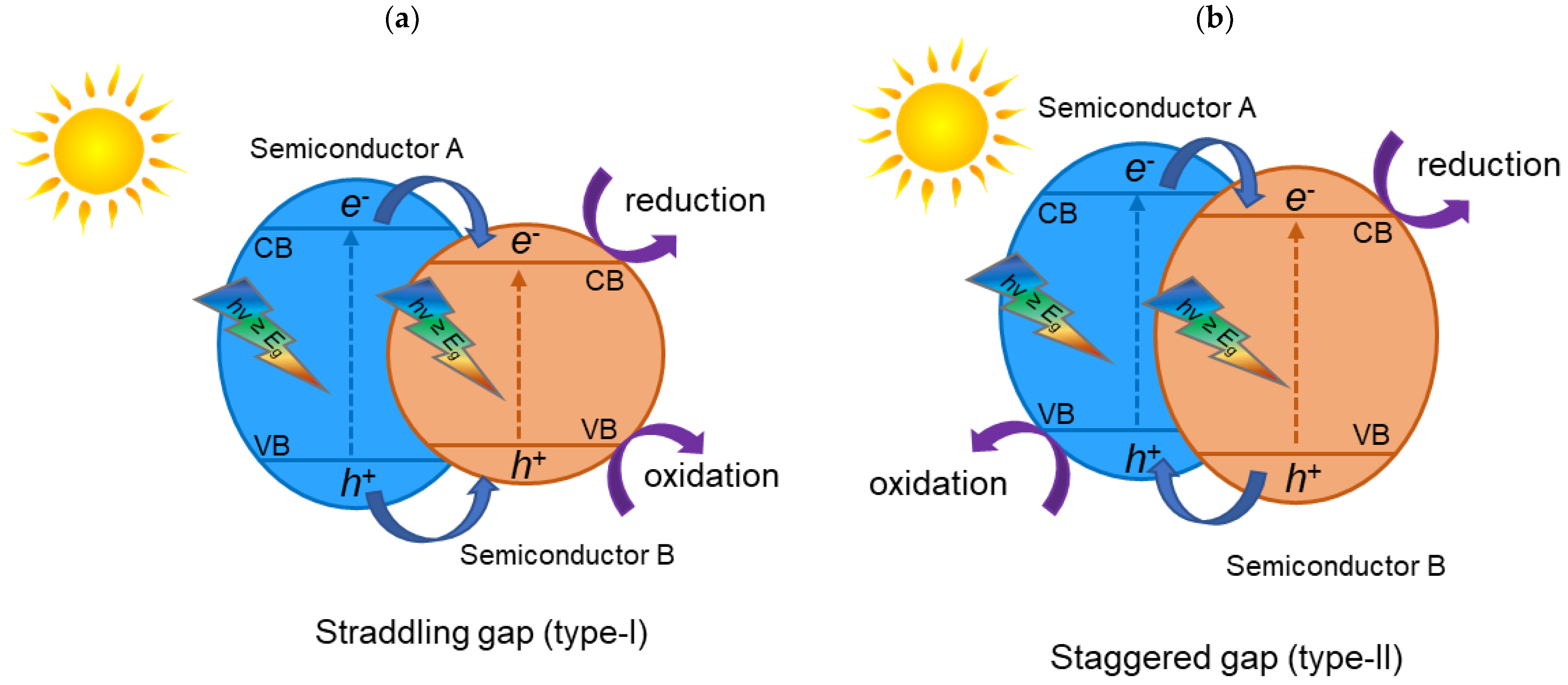
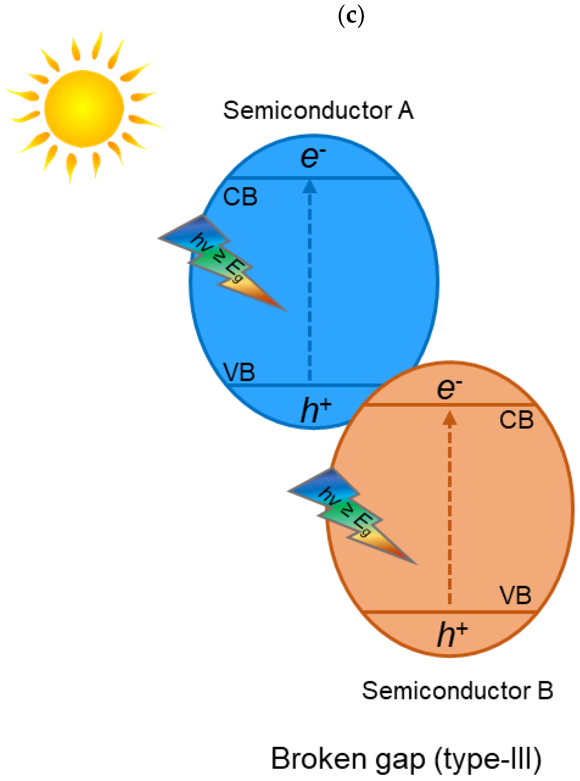
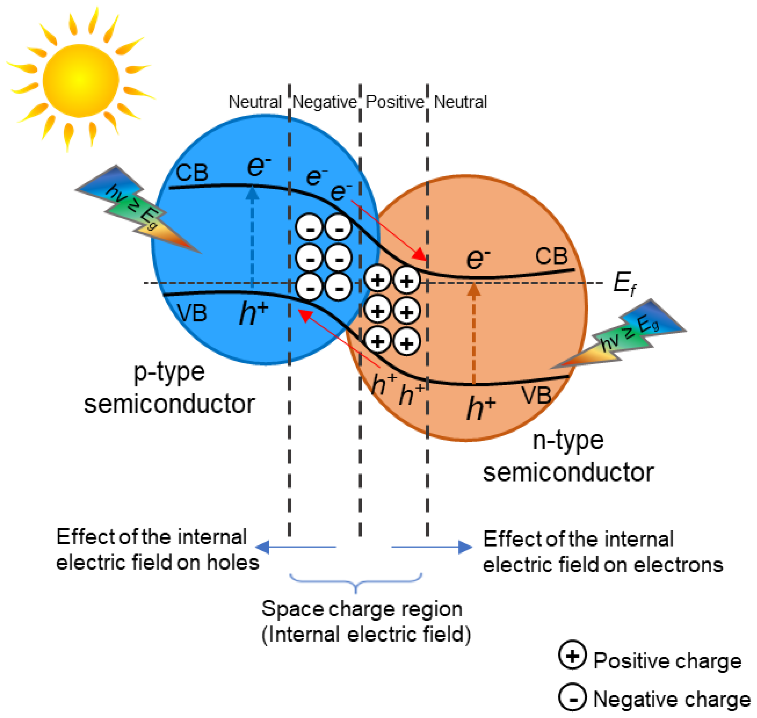
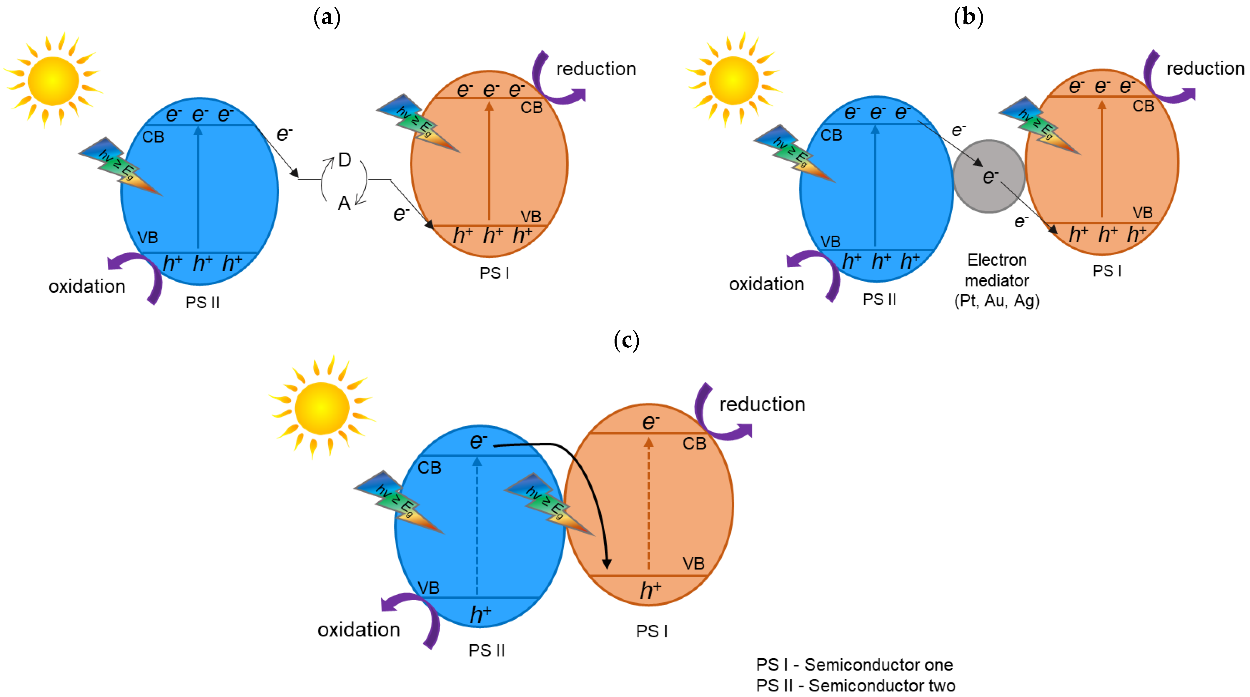
- The migration pathways of photogenerated electron–hole pairs need to be thoroughly studied. Heterojunction photocatalysts can have different arrangements (e.g., heterojunction type II or Z-scheme heterojunction) and, thus, different migration pathways for electron–hole separation, which need to be thoroughly studied and confirmed using advanced characterization techniques.
- To better understand the mechanism of migration pathways, knowledge from modeling methods or theoretical calculations should be used.
Author Contributions
Funding
Conflicts of Interest
References
- Hannah, R.; Roser, M. CO2 and greenhouse gas emissions. Our World Data 2017. Available online: https://ourworldindata.org/co2-and-other-greenhouse-gas-emissions (accessed on 15 October 2021).
- Lee, C.W.; Yang, K.D.; Nam, D.-H.; Jang, J.H.; Cho, N.H.; Im, S.W.; Nam, K.T. Defining a materials database for the design of copper binary alloy catalysts for electrochemical CO2 conversion. Adv. Mater. 2018, 30, 1704717. [Google Scholar] [CrossRef] [PubMed]
- Appel, A.M.; Bercaw, J.E.; Bocarsly, A.B.; Dobbek, H.; DuBois, D.L.; Dupuis, M.; Ferry, J.G.; Fujita, E.; Hille, R.; Kenis, P.J.A.; et al. Frontiers, Opportunities, and challenges in biochemical and chemical catalysis of CO2 fixation. Chem. Rev. 2013, 113, 6621–6658. [Google Scholar] [CrossRef] [Green Version]
- Kočí, K.; Dang Van, H.; Edelmannová, M.; Reli, M.; Wu, J.C.S. Photocatalytic reduction of CO2 using Pt/C3N4 photocatalyts. Appl. Surf. Sci. 2020, 503, 144426. [Google Scholar] [CrossRef]
- Habisreutinger, S.N.; Schmidt-Mende, L.; Stolarczyk, J.K. Photocatalytic reduction of CO2 on TiO2 and other semiconductors. Angew. Chem. Int. Ed. 2013, 52, 7372–7408. [Google Scholar] [CrossRef] [PubMed]
- Hiragond, C.; Ali, S.; Sorcar, S.; In, S.-I. Hierarchical nanostructured photocatalysts for CO2 photoreduction. Catalysts 2019, 9, 370. [Google Scholar] [CrossRef] [Green Version]
- Ziarati, A.; Badiei, A.; Grillo, R.; Burgi, T. 3D Yolk@Shell TiO2–x/LDH architecture: Tailored structure for visible light CO2 conversion. ACS Appl. Mater. Interfaces 2019, 11, 5903–5910. [Google Scholar] [CrossRef]
- Nguyen, T.P.; Nguyen, D.L.T.; Nguyen, V.-H.; Le, T.-H.; Vo, D.-V.N.; Trinh, Q.T.; Bae, S.-R.; Chae, S.Y.; Kim, S.Y.; Le, Q.V. Recent advances in TiO2-based photocatalysts for reduction of CO2 to fuels. Nanomaterials 2020, 10, 337. [Google Scholar] [CrossRef] [Green Version]
- Gao, Y.; Qian, K.; Xu, B.; Li, Z.; Zheng, J.; Zhao, S.; Ding, F.; Sun, Y.; Xu, Z. Recent advances in visible-light-driven conversion of CO2 by photocatalysts into fuels or value-added chemicals. Carbon Resour. Convers. 2020, 3, 46–59. [Google Scholar] [CrossRef]
- Li, K.; Teng, C.; Wang, S.; Min, Q. Recent advances in TiO2-based heterojunctions for photocatalytic CO2 reduction with water oxidation: A Review. Front. Chem. 2021, 9, 637501. [Google Scholar] [CrossRef]
- Inoue, T.; Fujishima, A.; Konishi, S.; Honda, K. Photoelectrocatalytic reduction of carbon dioxide in aqueous suspensions of semiconductor powders. Nature 1979, 277, 637–638. [Google Scholar] [CrossRef]
- Wei, L.; Yu, C.; Zhang, Q.; Liu, H.; Wang, Y. TiO2-based heterojunction photocatalysts for photocatalytic reduction of CO2 into solar fuels. J. Mater. Chem. 2018, 6, 22411–22436. [Google Scholar] [CrossRef]
- Ohtani, B.; Handa, J.-i.; Nishimoto, S.-i.; Kagiya, T. Highly active semiconductor photocatalyst: Extra-fine crystallite of brookite TiO2 for redox reaction in aqueous propan-2-ol and/or silver sulfate solution. Chem. Phys. Lett. 1985, 120, 292–294. [Google Scholar] [CrossRef]
- Li, Y.; Zhou, M.; Cheng, B.; Shao, Y. Recent advances in g-C3N4-based heterojunction photocatalysts. J. Mater. Sci. Technol. 2020, 56, 1–17. [Google Scholar] [CrossRef]
- Liu, X.; Dang, R.; Dong, W.; Huang, X.; Tang, J.; Gao, H.; Wang, G. A sandwich-like heterostructure of TiO2 nanosheets with MIL-100(Fe): A platform for efficient visible-light-driven photocatalysis. Appl. Catal. B 2017, 209, 506–513. [Google Scholar] [CrossRef]
- Xiong, Z.; Wang, H.; Xu, N.; Li, H.; Fang, B.; Zhao, Y.; Zhang, J.; Zheng, C. Photocatalytic reduction of CO2 on Pt2+–Pt0/TiO2 nanoparticles under UV/Vis light irradiation: A combination of Pt2+ doping and Pt nanoparticles deposition. Int. J. Hydrogen Energy 2015, 40, 10049–10062. [Google Scholar] [CrossRef]
- Liu, X.; Dong, G.; Li, S.; Lu, G.; Bi, Y. Direct observation of charge separation on anatase TiO2 crystals with selectively etched {001} facets. J. Am. Chem. Soc. 2016, 138, 2917–2920. [Google Scholar] [CrossRef]
- Low, J.; Yu, J.; Jaroniec, M.; Wageh, S.; Al-Ghamdi, A.A. Heterojunction photocatalysts. Adv. Mater. 2017, 29, 1601694. [Google Scholar] [CrossRef]
- Low, J.; Yu, J.; Jiang, C. Design and fabrication of direct Z-scheme photocatalysts. In Interface Science and Technology; Yu, J., Jaroniec, M., Jiang, C., Eds.; Elsevier: Amsterdam, The Netherlands, 2020; Volume 31, pp. 193–229. [Google Scholar]
- Bard, A.J. Photoelectrochemistry and heterogeneous photo-catalysis at semiconductors. J. Photochem. Photobiol. 1979, 10, 59–75. [Google Scholar] [CrossRef]
- Tada, H.; Mitsui, T.; Kiyonaga, T.; Akita, T.; Tanaka, K. All-solid-state Z-scheme in CdS-Au-TiO2 three-component nanojunction system. Nat. Mater. 2006, 5, 782–786. [Google Scholar] [CrossRef]
- Yu, J.; Wang, S.; Low, J.; Xiao, W. Enhanced photocatalytic performance of direct Z-scheme g-C3N4–TiO2 photocatalysts for the decomposition of formaldehyde in air. Phys. Chem. Chem. Phys. 2013, 15, 16883–16890. [Google Scholar] [CrossRef]
- Yang, C.; Qin, J.; Xue, Z.; Ma, M.; Zhang, X.; Liu, R. Rational design of carbon-doped TiO2 modified g-C3N4 via in-situ heat treatment for drastically improved photocatalytic hydrogen with excellent photostability. Nano Energy 2017, 41, 1–9. [Google Scholar] [CrossRef]
- Lu, N.; Wang, C.; Sun, B.; Gao, Z.; Su, Y. Fabrication of TiO2-doped single layer graphitic-C3N4 and its visible-light photocatalytic activity. Sep. Purif. Technol. 2017, 186, 226–232. [Google Scholar] [CrossRef]
- Shi, H.; Long, S.; Hu, S.; Hou, J.; Ni, W.; Song, C.; Li, K.; Gurzadyan, G.G.; Guo, X. Interfacial charge transfer in 0D/2D defect-rich heterostructures for efficient solar-driven CO2 reduction. Appl. Catal. B 2019, 245, 760–769. [Google Scholar] [CrossRef]
- Reli, M.; Huo, P.; Šihor, M.; Ambrožová, N.; Troppová, I.; Matějová, L.; Lang, J.; Svoboda, L.; Kuśtrowski, P.; Ritz, M.; et al. Novel TiO2/C3N4 photocatalysts for photocatalytic reduction of CO2 and for photocatalytic decomposition of N2O. J. Phys. Chem. A 2016, 120, 8564–8573. [Google Scholar] [CrossRef]
- Zhang, L.; Xie, C.; Jiu, H.; Meng, Y.; Zhang, Q.; Gao, Y. Synthesized hollow TiO2@g-C3N4 composites for carbon dioxide reduction under visible light. Catal. Lett. 2018, 148, 2812–2821. [Google Scholar] [CrossRef]
- Banitalebi Dehkordi, A.; Ziarati, A.; Ghasemi, J.B.; Badiei, A. Preparation of hierarchical g-C3N4@TiO2 hollow spheres for enhanced visible-light induced catalytic CO2 reduction. Sol. Energy 2020, 205, 465–473. [Google Scholar] [CrossRef]
- Zhou, S.; Liu, Y.; Li, J.; Wang, Y.; Jiang, G.; Zhao, Z.; Wang, D.; Duan, A.; Liu, J.; Wei, Y. Facile in situ synthesis of graphitic carbon nitride (g-C3N4)-N-TiO2 heterojunction as an efficient photocatalyst for the selective photoreduction of CO2 to CO. Appl. Catal. B 2014, 158–159, 20–29. [Google Scholar] [CrossRef]
- Thanh Truc, N.T.; Giang Bach, L.; Thi Hanh, N.; Pham, T.-D.; Thi Phuong Le Chi, N.; Tran, D.T.; Nguyen, M.V.; Nguyen, V.N. The superior photocatalytic activity of Nb doped TiO2/g-C3N4 direct Z-scheme system for efficient conversion of CO2 into valuable fuels. J. Colloid Interface Sci. 2019, 540, 1–8. [Google Scholar] [CrossRef]
- Li, H.; Gao, Y.; Wu, X.; Lee, P.-H.; Shih, K. Fabrication of heterostructured g-C3N4/Ag-TiO2 hybrid photocatalyst with enhanced performance in photocatalytic conversion of CO2 under simulated sunlight irradiation. Appl. Surf. Sci. 2017, 402, 198–207. [Google Scholar] [CrossRef]
- Liu, C.; Raziq, F.; Li, Z.; Qu, Y.; Zada, A.; Jing, L. Synthesis of TiO2/g-C3N4 nanocomposites with phosphate–oxygen functional bridges for improved photocatalytic activity. Chin. J. Catal. 2017, 38, 1072–1078. [Google Scholar] [CrossRef]
- Sun, R.; Jiang, X.; Zhang, M.; Ma, Y.; Jiang, X.; Liu, Z.; Wang, Y.; Yang, J.; Xie, M.; Han, W. Dual quantum dots decorated TiO2 nanorod arrays for efficient CO2 reduction. J. Catal. 2019, 378, 192–200. [Google Scholar] [CrossRef]
- Wang, Y.; Li, B.; Zhang, C.; Cui, L.; Kang, S.; Li, X.; Zhou, L. Ordered mesoporous CeO2-TiO2 composites: Highly efficient photocatalysts for the reduction of CO2 with H2O under simulated solar irradiation. Appl. Catal. B 2013, 130–131, 277–284. [Google Scholar] [CrossRef]
- Abdullah, H.; Khan, M.R.; Pudukudy, M.; Yaakob, Z.; Ismail, N.A. CeO2-TiO2 as a visible light active catalyst for the photoreduction of CO2 to methanol. J. Rare Earths 2015, 33, 1155–1161. [Google Scholar] [CrossRef] [Green Version]
- Jiao, J.; Wei, Y.; Zhao, Z.; Liu, J.; Li, J.; Duan, A.; Jiang, G. Photocatalysts of 3D Ordered Macroporous TiO2-Supported CeO2 nanolayers: Design, Preparation, and their catalytic performances for the reduction of CO2 with H2O under simulated solar irradiation. Ind. Eng. Chem. Res. 2014, 53, 17345–17354. [Google Scholar] [CrossRef]
- Zhao, J.; Wang, Y.; Li, Y.; Yue, X.; Wang, C. Phase-dependent enhancement for CO2 photocatalytic reduction over CeO2/TiO2 catalysts. Catal. Sci. Technol. 2016, 6, 7967–7975. [Google Scholar] [CrossRef]
- Wang, Y.; Zhao, J.; Wang, T.; Li, Y.; Li, X.; Yin, J.; Wang, C. CO2 photoreduction with H2O vapor on highly dispersed CeO2/TiO2 catalysts: Surface species and their reactivity. J. Catal. 2016, 337, 293–302. [Google Scholar] [CrossRef]
- Qin, S.; Xin, F.; Liu, Y.; Yin, X.; Ma, W. Photocatalytic reduction of CO2 in methanol to methyl formate over CuO–TiO2 composite catalysts. J. Colloid Interface Sci. 2011, 356, 257–261. [Google Scholar] [CrossRef]
- Méndez-Medrano, M.G.; Kowalska, E.; Lehoux, A.; Herissan, A.; Ohtani, B.; Bahena, D.; Briois, V.; Colbeau-Justin, C.; Rodríguez-López, J.L.; Remita, H. Surface modification of TiO2 with Ag nanoparticles and CuO nanoclusters for application in photocatalysis. J. Phys. Chem. C 2016, 120, 5143–5154. [Google Scholar] [CrossRef]
- Zhao, Y.; Chen, J.; Cai, W.; Bu, Y.; Huang, Q.; Tao, T.; Lu, J. CuO-decorated dual-phase TiO2 microspheres with enhanced activity for photocatalytic CO2 reduction in liquid–solid regime. Chem. Phys. Lett. 2019, 725, 66–74. [Google Scholar] [CrossRef]
- Li, H.; Li, C.; Han, L.; Li, C.; Zhang, S. Photocatalytic reduction of CO2 with H2O on CuO/TiO2 catalysts. Energy Sources A Recovery Util. Environ. Eff. 2016, 38, 420–426. [Google Scholar] [CrossRef]
- Razali, M.H.; Yusoff, M. Highly efficient CuO loaded TiO2 nanotube photocatalyst for CO2 photoconversion. Mater. Lett. 2018, 221, 168–171. [Google Scholar] [CrossRef]
- Park, H.; Ou, H.-H.; Kang, U.; Choi, J.; Hoffmann, M.R. Photocatalytic conversion of carbon dioxide to methane on TiO2/CdS in aqueous isopropanol solution. Catal. Today 2016, 266, 153–159. [Google Scholar] [CrossRef] [Green Version]
- Low, J.; Dai, B.; Tong, T.; Jiang, C.; Yu, J. In situ irradiated X-ray photoelectron spectroscopy investigation on a direct Z-Scheme TiO2/CdS composite film photocatalyst. Adv. Mater. 2019, 31, 1802981. [Google Scholar] [CrossRef] [PubMed]
- Song, G.; Xin, F.; Chen, J.; Yin, X. Photocatalytic reduction of CO2 in cyclohexanol on CdS–TiO2 heterostructured photocatalyst. Appl. Catal. A 2014, 473, 90–95. [Google Scholar] [CrossRef]
- Ahmad Beigi, A.; Fatemi, S.; Salehi, Z. Synthesis of nanocomposite CdS/TiO2 and investigation of its photocatalytic activity for CO2 reduction to CO and CH4 under visible light irradiation. J. CO2 Util. 2014, 7, 23–29. [Google Scholar] [CrossRef]
- Khalilzadeh, A.; Shariati, A. Photoreduction of CO2 over heterogeneous modified TiO2 nanoparticles under visible light irradiation: Synthesis, process and kinetic study. Sol. Energy 2018, 164, 251–261. [Google Scholar] [CrossRef]
- Jia, P.-y.; Guo, R.-t.; Pan, W.-g.; Huang, C.-y.; Tang, J.-y.; Liu, X.-y.; Qin, H.; Xu, Q.-y. The MoS2/TiO2 heterojunction composites with enhanced activity for CO2 photocatalytic reduction under visible light irradiation. Colloids Surf. A Physicochem. Eng. Asp. 2019, 570, 306–316. [Google Scholar] [CrossRef]
- Xu, F.Y.; Zhu, B.C.; Cheng, B.; Yu, J.G.; Xu, J.S. 1D/2D TiO2/MoS2 hybrid nanostructures for enhanced photocatalytic CO2 reduction. Adv. Opt. Mater. 2018, 6, 1800911. [Google Scholar] [CrossRef] [Green Version]
- Tu, W.; Li, Y.; Kuai, L.; Zhou, Y.; Xu, Q.; Li, H.; Wang, X.; Xiao, M.; Zou, Z. Construction of unique two-dimensional MoS2–TiO2 hybrid nanojunctions: MoS2 as a promising cost-effective cocatalyst toward improved photocatalytic reduction of CO2 to methanol. Nanoscale 2017, 9, 9065–9070. [Google Scholar] [CrossRef]
- Marci, G.; Garcia-Lopez, E.I.; Palmisano, L. Photocatalytic CO2 reduction in gas-solid regime in the presence of H2O by using GaP/TiO2 composite as photocatalyst under simulated solar light. Catal. Commun. 2014, 53, 38–41. [Google Scholar] [CrossRef] [Green Version]
- Truong, Q.D.; Liu, J.-Y.; Chung, C.-C.; Ling, Y.-C. Photocatalytic reduction of CO2 on FeTiO3/TiO2 photocatalyst. Catal. Commun. 2012, 19, 85–89. [Google Scholar] [CrossRef]
- Lin, J.; Hu, J.; Qiu, C.; Huang, H.; Chen, L.; Xie, Y.; Zhang, Z.; Lin, H.; Wang, X. In situ hydrothermal etching fabrication of CaTiO3 on TiO2 nanosheets with heterojunction effects to enhance CO2 adsorption and photocatalytic reduction. Catal. Sci. Technol. 2019, 9, 336–346. [Google Scholar] [CrossRef]
- Yin, S.; Han, J.; Zhou, T.; Xu, R. Recent progress in g-C3N4 based low cost photocatalytic system: Activity enhancement and emerging applications. Catal. Sci. Technol. 2015, 5, 5048–5061. [Google Scholar] [CrossRef] [Green Version]
- Raizada, P.; Kumar, A.; Hasija, V.; Singh, P.; Thakur, V.K.; Khan, A.A.P. An overview of converting reductive photocatalyst into all solid-state and direct Z-scheme system for water splitting and CO2 reduction. J. Ind. Eng. Chem. 2021, 93, 1–27. [Google Scholar] [CrossRef]
- Jourshabani, M.; Shariatinia, Z.; Badiei, A. Sulfur-doped mesoporous carbon nitride decorated with Cu particles for efficient photocatalytic degradation under visible-light irradiation. J. Phys. Chem. C 2017, 121, 19239–19253. [Google Scholar] [CrossRef]
- Jiang, Z.; Wan, W.; Li, H.; Yuan, S.; Zhao, H.; Wong, P.K. A hierarchical Z-Scheme α-Fe2O3/g-C3N4 hybrid for enhanced photocatalytic CO2 reduction. Adv. Mater. 2018, 30, 1706108. [Google Scholar] [CrossRef]
- Ong, W.-J.; Tan, L.-L.; Ng, Y.H.; Yong, S.-T.; Chai, S.-P. Graphitic carbon nitride (g-C3N4)-based photocatalysts for artificial photosynthesis and environmental remediation: Are we a step closer to achieving sustainability? Chem. Rev. 2016, 116, 7159–7329. [Google Scholar] [CrossRef]
- Zhao, Y.; Lin, Y.; Wang, G.; Jiang, Z.; Zhang, R.; Zhu, C. Electronic and optical performances of (Cu, N) codoped TiO2/g-C3N4 heterostructure photocatalyst: A spin-polarized DFT + U study. Sol. Energy 2018, 162, 306–316. [Google Scholar] [CrossRef]
- Chen, Y.; Huang, W.; He, D.; Situ, Y.; Huang, H. Construction of Heterostructured g-C3N4/Ag/TiO2 Microspheres with Enhanced Photocatalysis Performance under Visible-Light Irradiation. ACS Appl. Mater. Interfaces 2014, 6, 14405–14414. [Google Scholar] [CrossRef]
- Jiang, G.; Cao, J.; Chen, M.; Zhang, X.; Dong, F. Photocatalytic NO oxidation on N-doped TiO2/g-C3N4 heterojunction: Enhanced efficiency, mechanism and reaction pathway. Appl. Surf. Sci. 2018, 458, 77–85. [Google Scholar] [CrossRef]
- Liu, R.; Bie, Y.; Qiao, Y.; Liu, T.; Song, Y. Design of g-C3N4/TiO2 nanotubes heterojunction for enhanced organic pollutants degradation in waste water. Mater. Lett. 2019, 251, 126–130. [Google Scholar] [CrossRef]
- Das, A.; Patra, M.; Kumar, P.M.; Bhagavathiachari, M.; Nair, R.G. Defect-induced visible-light-driven photocatalytic and photoelectrochemical performance of ZnO–CeO2 nanoheterojunctions. J. Alloys Compd. 2021, 858, 157730. [Google Scholar] [CrossRef]
- Islam, M.J.; Reddy, D.A.; Choi, J.; Kim, T.K. Surface oxygen vacancy assisted electron transfer and shuttling for enhanced photocatalytic activity of a Z-scheme CeO2-AgI nanocomposite. RSC Adv. 2016, 6, 19341–19350. [Google Scholar] [CrossRef]
- Basha, M.H.; Ramu, C.; Gopal, N.O.; Reddy, M.V.B. Structural and spectroscopic characterizations of boron doped TiO2–CeO2 nanocomposite synthesized by solution combustion technique for photocatalytic applications. J. Mol. Struct. 2021, 1231, 129892. [Google Scholar] [CrossRef]
- Patil, P.; Nakate, U.T.; Nakate, Y.T.; Ambare, R.C. Acetaldehyde sensing properties using ultrafine CuO nanoparticles. Mater. Sci. Semicond. Process. 2019, 101, 76–81. [Google Scholar] [CrossRef]
- Zhang, H.; Wang, K.; Wang, L.; Xie, H.; Yu, W. Mesoporous CuO with full spectrum absorption for photothermal conversion in direct absorption solar collectors. Sol. Energy 2020, 201, 628–637. [Google Scholar] [CrossRef]
- Avila-Lopez, M.A.; Luevano-Hipolito, E.; Torres-Martinez, L.M. CuO coatings on glass fibers: A hybrid material for CO2 adsorption and photocatalytic reduction to solar fuels. J. Mater. Sci.—Mater. Electron. 2021, 32, 11336–11337. [Google Scholar] [CrossRef]
- Avila-Lopez, M.A.; Luevano-Hipolito, E.; Torres-Martinez, L.M. CO2 adsorption and its visible-light-driven reduction using CuO synthesized by an eco-friendly sonochemical method. J. Photochem. Photobiol. A—Chem. 2019, 382, 10. [Google Scholar] [CrossRef]
- Yan, Y.; Yu, Y.; Cao, C.; Huang, S.; Yang, Y.; Yang, X.; Cao, Y. Enhanced photocatalytic activity of TiO2–Cu/C with regulation and matching of energy levels by carbon and copper for photoreduction of CO2 into CH4. CrystEngComm 2016, 18, 2956–2964. [Google Scholar] [CrossRef]
- Nogueira, A.E.; Oliveira, J.A.; da Silva, G.T.S.T.; Ribeiro, C. Insights into the role of CuO in the CO2 photoreduction process. Sci. Rep. 2019, 9, 1316. [Google Scholar] [CrossRef] [Green Version]
- Wang, Q.; Lian, J.; Ma, Q.; Zhang, S.; He, J.; Zhong, J.; Li, J.; Huang, H.; Su, B. Preparation of carbon spheres supported CdS photocatalyst for enhancement its photocatalytic H2 evolution. Catal. Today 2017, 281, 662–668. [Google Scholar] [CrossRef]
- Meng, H.L.; Cui, C.; Shen, H.L.; Liang, D.Y.; Xue, Y.Z.; Li, P.G.; Tang, W.H. Synthesis and photocatalytic activity of TiO2@CdS and CdS@TiO2 double-shelled hollow spheres. J. Alloys Compd. 2012, 527, 30–35. [Google Scholar] [CrossRef]
- Li, X.; Chen, J.; Li, H.; Li, J.; Xu, Y.; Liu, Y.; Zhou, J. Photoreduction of CO2 to methanol over Bi2S3/CdS photocatalyst under visible light irradiation. J. Nat. Gas Chem. 2011, 20, 413–417. [Google Scholar] [CrossRef]
- Jang, J.S.; Park, H. Strategic Design of Heterojunction CdS Photocatalysts for Solar Hydrogen. In Materials and Processes for Solar Fuel Production; Viswanathan, B., Subramanian, V., Lee, J.S., Eds.; Springer: New York, NY, USA, 2014; pp. 1–22. [Google Scholar]
- Tan, C.; Zhang, H. Two-dimensional transition metal dichalcogenide nanosheet-based composites. Chem. Soc. Rev. 2015, 44, 2713–2731. [Google Scholar] [CrossRef] [PubMed]
- Xiang, Q.; Yu, J.; Jaroniec, M. Synergetic effect of MoS2 and graphene as cocatalysts for enhanced photocatalytic H2 production activity of TiO2 nanoparticles. J. Am. Chem. Soc. 2012, 134, 6575–6578. [Google Scholar] [CrossRef] [PubMed]
- Chen, B.; Meng, Y.; Sha, J.; Zhong, C.; Hu, W.; Zhao, N. Preparation of MoS2/TiO2 based nanocomposites for photocatalysis and rechargeable batteries: Progress, challenges, and perspective. Nanoscale 2018, 10, 34–68. [Google Scholar] [CrossRef] [PubMed]
- Zhou, W.; Yin, Z.; Du, Y.; Huang, X.; Zeng, Z.; Fan, Z.; Liu, H.; Wang, J.; Zhang, H. Synthesis of few-layer MoS2 nanosheet-coated TiO2 nanobelt heterostructures for enhanced photocatalytic activities. Small 2013, 9, 140–147. [Google Scholar] [CrossRef]
- Halmann, M. Photoelectrochemical reduction of aqueous carbon dioxide on p-type gallium phosphide in liquid junction solar cells. Nature 1978, 275, 115–116. [Google Scholar] [CrossRef]
- Barton, E.E.; Rampulla, D.M.; Bocarsly, A.B. Selective Solar-Driven Reduction of CO2 to Methanol Using a Catalyzed p-GaP Based Photoelectrochemical Cell. J. Am. Chem. Soc. 2008, 130, 6342–6344. [Google Scholar] [CrossRef]
- Cañas-Martínez, D.M.; Cipagauta-Díaz, S.; Manrique, M.; Gómez, R.; Pedraza-Avella, J.A. Photocatalytic hydrogen production using FeTiO3 concentrates modified by high energy ball milling and the presence of Mg precursors. Top. Catal. 2021, 64, 2–16. [Google Scholar] [CrossRef]
- Cañas-Martínez, D.M.; Gauthier, G.H.; Pedraza-Avella, J.A. Photo-oxidative and photo-reductive capabilities of ilmenite-rich black sand concentrates using methyl orange as a probe molecule. Photochem. Photobiol. Sci. 2019, 18, 912–919. [Google Scholar] [CrossRef] [PubMed]
- Moradi, M.; Vasseghian, Y.; Khataee, A.; Harati, M.; Arfaeinia, H. Ultrasound-assisted synthesis of FeTiO3/GO nanocomposite for photocatalytic degradation of phenol under visible light irradiation. Sep. Purif. Technol. 2021, 261, 118274. [Google Scholar] [CrossRef]
- Xiao, W.; Lu, X.-g.; Zou, X.-l.; Wei, X.-m.; Ding, W.-z. Phase transitions, micro-morphology and its oxidation mechanism in oxidation of ilmenite (FeTiO3) powder. Trans. Nonferrous Met. Soc. China 2013, 23, 2439–2445. [Google Scholar] [CrossRef]
- Baysal, Z.; Kirchner, J.; Mehne, M.; Kureti, S. Study on the reduction of ilmenite-type FeTiO3 by H2. Int. J. Hydrogen Energy 2021, 46, 4447–4459. [Google Scholar] [CrossRef]
- García-Muñoz, P.; Pliego, G.; Zazo, J.A.; Bahamonde, A.; Casas, J.A. Ilmenite (FeTiO3) as low cost catalyst for advanced oxidation processes. J. Environ. Chem. Eng. 2016, 4, 542–548. [Google Scholar] [CrossRef]
- Gao, B.; Yang, C.; Chen, J.; Ma, Y.; Xie, J.; Zhang, H.; Wei, L.; Li, Q.; Du, J.; Xu, Q. Ferromagnetic photocatalysts of FeTiO3–Fe2O3 nanocomposites. RSC Adv. 2017, 7, 54594–54602. [Google Scholar] [CrossRef] [Green Version]
- Zarazúa-Morín, M.E.; Torres-Martínez, L.M.; Moctezuma, E.; Juárez-Ramírez, I.; Zermeño, B.B. Synthesis, characterization, and catalytic activity of FeTiO3/TiO2 for photodegradation of organic pollutants with visible light. Res. Chem. Intermed. 2016, 42, 1029–1043. [Google Scholar] [CrossRef]
- Gao, B.; Kim, Y.J.; Chakraborty, A.K.; Lee, W.I. Efficient decomposition of organic compounds with FeTiO3/TiO2 heterojunction under visible light irradiation. Appl. Catal. B 2008, 83, 202–207. [Google Scholar] [CrossRef]
- Passi, M.; Pal, B. A review on CaTiO3 photocatalyst: Activity enhancement methods and photocatalytic applications. Powder Technol. 2021, 388, 274–304. [Google Scholar] [CrossRef]
- Cesconeto, F.R.; Borlaf, M.; Nieto, M.I.; de Oliveira, A.P.N.; Moreno, R. Synthesis of CaTiO3 and CaTiO3/TiO2 nanoparticulate compounds through Ca2+/TiO2 colloidal sols: Structural and photocatalytic characterization. Ceram. Int. 2018, 44, 301–309. [Google Scholar] [CrossRef]
- Zhu, Y.; Zhu, D.; Yan, Q.; Gao, G.; Xu, J.; Liu, Y.; Alahakoon, S.B.; Rahman, M.M.; Ajayan, P.M.; Egap, E.; et al. Metal Oxide Catalysts for the Synthesis of Covalent Organic Frameworks and One-Step Preparation of Covalent Organic Framework-Based Composites. Chem. Mater. 2021, 33, 6158–6165. [Google Scholar] [CrossRef]
- Zhang, M.; Lu, M.; Lang, Z.-L.; Liu, J.; Liu, M.; Chang, J.-N.; Li, L.-Y.; Shang, L.-J.; Wang, M.; Li, S.-L.; et al. Semiconductor/Covalent-Organic-Framework Z-Scheme Heterojunctions for Artificial Photosynthesis. Angew. Chem. Int. Ed. 2020, 59, 6500–6506. [Google Scholar] [CrossRef] [PubMed]


| Reaction | E° (V vs. NHE) | Product | Reference |
|---|---|---|---|
| −0.41 | Hydrogen | [8] | |
| −1.90 | anion radical | [9] | |
| −0.87 | Oxalate | [8] | |
| −0.61 | Formic acid | [10] | |
| −0.53 | Carbon monoxide | [9,10] | |
| −0.48 | Formaldehyde | [8,9,10] | |
| −0.38 | Methanol | [9,10] | |
| −0.33 | Ethanol | [8] | |
| −0.27 | Ethane | [8] | |
| −0.24 | Methane | [8,9,10] |
| Photocatalysts | CO2 Photoreduction Condition | Yield of Products | Type of Heterojunction | Ref. | ||||
|---|---|---|---|---|---|---|---|---|
| Type | Prepared | Reaction Mixture | Light Source | Conditions | ||||
| TiO2−x/g-C3N4 | Solid state synthesis | CO2 (99.999%), 5 mL of solution containing 4 mL of methyl cyanide (MeCN) solvent, 1 mL of triethanolamine (TEOA), bipyridine (bpy) (10 mmol L−1) and 25 μL of 20 mmol L−1 CoCl2 aqueous solution | 300 W xenon lamp | 43 mL quartz vessel with a rubber septum; 25 °C; circulation cooling system. Photocatalyst concentration in 1 g L−1 | CO = 77.8 μmol g−1 h−1 | Type-II 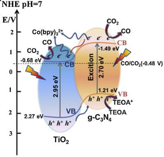 | * | [25] |
| (0.3/1)TiO2/g-C3N4 | Simple mechanical mixing of pure g-C3N4 and commercial TiO2 Evonik P25 | CO2 with a certified maximum of hydrocarbons less than 1 ppm (SIAD Technical Gases, CZ) | 8 W Hg lamp | Cylindrical stirred batch reactor, with internal volume of 355 cm3 Photocatalyst concentration in 0.28 g L−1 | CH4 = 70 μmol gcat.−1 CO = 23 μmol gcat.−1 after 8 h | Type-II 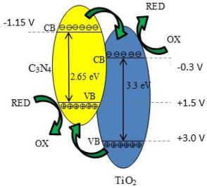 | ‡ | [26] |
| TiO2@g-C3N4-20% | Stirring method | CO2 and 50 mL 0.08 mol L−1 NaHCO3 solution | 300 W Xe lamp with a 420 nm optical filter | quartz glass tube with a volume of 60 mL Photocatalyst concentration in 1 g L−1 | CH3OH ~50 μmol gcat−1 after 4 h | Type-II(see Ref. [27]) | - | [27] |
| HCNS@TiO2 | Templating method combined with the subsequent kinetically-controlled coating process | CO2 (high purity) and H2O (400 mL) | Visible-light (300 W Xenon lamp) | cylindrical Pyrex glass photoreactor with 500 mL of volume Photocatalyst concentration in 1 g L−1 | CH3OH = 52.1 μmol gcat−1 CH4 = 21.3 μmol gcat−1 after 6 h | Type-II 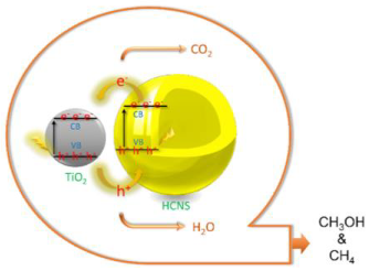 | † | [28] |
| 70:30 g-C3N4-N-TiO2 | Hydrothermal method and thermal treatment (in situ method) | Deionized H2O + CO2 (99.999%) | 300 W Xe arc lamp Intensity 100 mW/cm2 | 780 mL gas-closed circulation Teflon system Photocatalyst concentration in 0.13 g L−1 | CO = 14.73 μmol after 12 h | Type-II 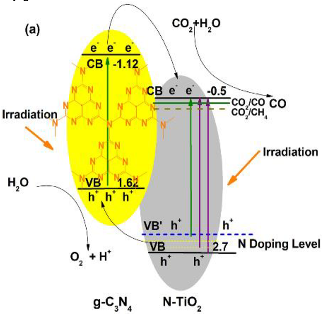 | ¥ | [29] |
| Nb-TiO2/g-C3N4 | Solid state synthesis | CO2 (99.99%) flow rate 20 mL/min; water vapor was used as hole scavenger | Two 30 W white bulbs | continuous gas system with a reactor (40 mL) located in the center of a dark cover cask using as a reaction chamber (24 L) Photocatalyst concentration in 2.5 g L−1 | CO = 420 μmol g−1 h−1 HCOOH = 698 μmol g−1 h−1 CH4 = 562 μmol g−1 h−1 | Z-scheme 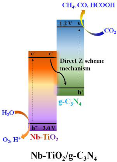 | § | [30] |
| 8 mass % g-C3N4/Ag-TiO2 | Solvent evaporation followed by calcination | CO2 flow rate 3 mL/min; water vapor was used as hole scavenger | 300 W xenon lamp | 70 mL cylindrical photoreactor Photocatalyst concentration in 0.7 g L−1 | CH4 = 28.0 μmol g−1 CO = 19.0 μmol g−1 after 3 h | Type-II  | ƗƗ | [31] |
| Phosphate–oxygen (P–O) bridged TiO2/g-C3N4 | Impregnation-solid state synthesis | CO2 + 3 mL H2O; water vapor was used as a hole scavenger | 300 W xenon lamp | cylindrical steel reactor (volume of 100 mL and area of 3.5 cm2) Photocatalyst concentration in 2 g L−1 | CH4 = 40 μmol g−1 h−1 CO = 15 μmol g−1 h−1 | Z-scheme 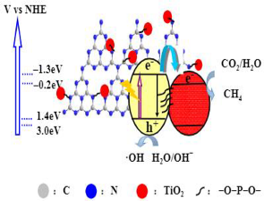 | I | [32] |
| (Au, C3N4)/TiO2 | Immersing (or dipping) method | CO2 + 5 mL H2O | 300 W Xenon arc lamp | 100 mL sealed steel container with cooling water Photocatalyst: Two pieces of samples (0.5 cm2/sample | CO = 0.138 µmol cm−2h−1 CH4 = 0.032 µmol cm−2h−1 | Z-scheme 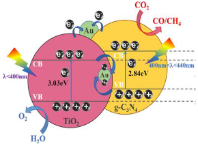 | II | [33] |
| Photocatalysts | CO2 Photoreduction Condition | Yield of Products | Type of Heterojunction | Ref. | ||||
|---|---|---|---|---|---|---|---|---|
| Type | Prepared | Reaction Mixture | Light Source | Conditions | ||||
| Mes-CeTi-1.0 | Template method using a nanocasting route | CO2 + H2O | Xe arc lamp 300 W | stainless steel reactor (volume of 1500 mL) Photocatalyst concentration in 0.07 g L−1 | CH4 = 11.5 mmol gcat−1 CO = ~70 mmol gcat−1 after 325 min | - | - | [34] |
| CeO2-TiO2 | Stirring method and calcination method | CO2 and 300 mL of 0.1 mol L−1 NaOH solution (for 30 min before irradiation) During irradiation CO2 was continuously bubbled | Visible light—500 W Xenon lamp, and 2 mol L−1 sodium nitrite solution (to remove UV light) | Pyrex glass reactor (500 mL) Photocatalyst concentration in 1 g L−1 | CH3OH = 18.6 μmol gcat−1 after 6 h | Type-II 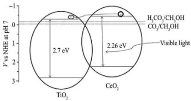 | * | [35] |
| CeO2/TiO2-4 | Gas bubbling-assisted membrane precipitation (GBMP) method | CO2 and H2O | 300 W Xe lamp and an optical filter with the absorbed light wavelength of <420 nm | Glass reactor (basal diameter of 4 cm) Photocatalyst amount 0.1 g | CO = 2.06 μmol after 6 h | Type-II 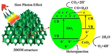 | ‡ | [36] |
| CeO2/TiO2 (R-TiCe0.1) | Hydrothermal method | CO2 and H2O (Gaseous CO2 of 8 kPa was in site produced by the reaction of NaHCO3 with a H2SO4 solution (0.5 M).) | 500 W Xenon lamp | reactor connected with mechanical vacuum pump Photocatalyst amount 10 mg | CO = 61.9 μmol g−1 CH4 = 23.5 μmol g−1 after 6 h | Type-II 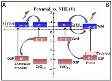 | † | [37] |
| 0.2CeO2/TiO2 | One-pot hydrothermal method | CO2 and H2O (Gaseous CO2 of 8 kPa was produced in situ by the reaction of NaHCO3 with a H2SO4 solution (0.5 M).) | 300 W Xenon lamp | reactor connected with mechanical vacuum pump Photocatalyst amount 10 mg | CO = 46.6 μmol g−1 CH4 = 30.2 μmol g−1 after 6 h | Type-II 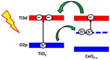 | ¥ | [38] |
| Photocatalysts | CO2 Photoreduction Condition | Yield of Products | Type of Heterojunction | Ref. | ||||
|---|---|---|---|---|---|---|---|---|
| Type | Prepared | Reaction Mixture | Light Source | Conditions | ||||
| CuO/TiO2(AB) | Impregnation method | pure CH3OH solution (30 mL), and pure CO2 gas | 250 W Hg lamp intensity 3900 μW/cm2 at 365 nm | ideal mixing 50 mL quartz tube Photocatalyst concentration in 1 g L−1 | HCOOCH3 = ~1800 μmol gcat−1 after 4 h | - | - | [41] |
| 3 wt.% CuO/TiO2 | Impregnation method | CO2 (Ultra high purity grade), 130 mL of 0.2 M KHCO3 and 0.1 M Na2SO3 aqueous solutions | 500 W high pressure Hg lamp with a peak light intensity at 365 nm | quartz reactor Photocatalyst concentration in 2.77 g L−1 | methanol = 12.5 μmol g−1 ethanol = 27.1 μmol g−1 after 6 h | -- | - | [42] |
| 1.0CuO-TiO2 | Stirring method followed by calcination | CO2 (99.99% purity) and 30 mL of methanol | 250 W high pressure mercury lamp with the radiation peak at about 365 nm | slurry reactor system Photocatalyst concentration in 1 g L−1 | Methyl formate ~1600 μmol g−1 h−1 | Z-scheme  | * | [39] |
| CuO loaded TiO2 nanotube | Hydrothermal method | CO2 (flow rate of 30 mL min−1) and ultrapure water, and NaHCO3 (0.1 M) | 400 W high-pressure mercury lamp with a quartz filter | flow system with an inner-irradiation-type reaction vessel at ambient pressure Photocatalyst amount 0.5 g | 100% CO2 conversion into CH4 and CH3OH after 2.5 h | Type-I 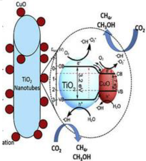 | ‡ | [43] |
| Photocatalysts | CO2 Photoreduction Condition | Yield of Products | Type of Heterojunction | Ref. | ||||
|---|---|---|---|---|---|---|---|---|
| Type | Prepared | Reaction Mixture | Light Source | Conditions | ||||
| TiO2/CdS-3 | Conventional hydrothermal technique | Ar or CO2 (both 99.99%) for 1 h, and aqueous isopropanol solution (1.0 M, 100 mL) | 450 W Xe arc lamp in combination with 320 nm or 420-nm-cutoff filters | airtight glass reactor (120 mL) with a quartz disc for light penetration Photocatalyst concentration in 1 g L−1 | methane = ~18 µmol (after 10 h) CO = ~2.5 µmol (after 10 h) Under UV-vis irradiation | Type-II 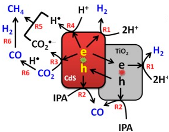 | * | [44] |
| TiO2/CdS | Ionic layer adsorption and reaction (SILAR) method | CO2 and H2O vapor (from 84 mg of NaHCO3 and 0.3 mL of HCl solution (4 M)) | 300 W Xenon arc lamp | 200 mL Pyrex reactor (purged with N2 gas) Photocatalyst: Film with 4 cm2 | 11.9 mmol h−1 m−2 for CH4 production | Z-scheme 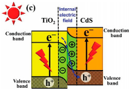 | ‡ | [45] |
| CdS-TiO2-8 | Hydrothermal method | CO2 and 10 mL cyclohexanol | 250 W high pressure mercury lamp | batch slurry bed reactor with inner capacity of 50 mL Photocatalyst concentration in 2 g L−1 | cyclohexyl formate = 20.2 µmol gcat−1h−1 cyclohexanone = 20 µmol gcat−1 h−1 | Z-Scheme 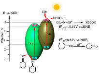 | † | [46] |
| CdS-TiO2 S3 (45%) | Hydrothermal method | N2 and CO2 | 125 W Hg lamp (350–400 nm) For the visible light, the UV wavelengths <400 nm were removed using a sodium nitrite solution (2.0 M) | Pyrex reactor with an effective volume of 125 mL Photocatalyst concentration in 1.44 g L−1 | Under UV-vis irradiation: CO = ~15.5 µmol gcat−1 CH4 = ~3.0 µmol gcat−1 after 8 h Under visible light irradiation: CO = ~10.3 µmol gcat−1 CH4 = ~1.5 µmol gcat−1 after 8 h | Type-II 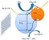 | ¥ | [47] |
| Photocatalysts | CO2 Photoreduction Condition | Yield of Products | Type of Heterojunction | Ref. | ||||
|---|---|---|---|---|---|---|---|---|
| Type | Prepared | Reaction Mixture | Light Source | Conditions | ||||
| 10% MoS2/TiO2 | Calcined at 300 °C for 4 h with argon shielding gas | 100 mL deionized H2O which was preprocessed for 30 min with CO2 (99.99%) of 100 kPa | Xe-arc lamp 300 W acting | 500 cm3 cylindrical reactor Photocatalyst concentration in 0.5 g L−1 | CO = 268.97 μmol gcat−1 CH4 = 49.93 μmol gcat−1 after 6 h | Type-II 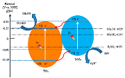 | * | [49] |
| 10% MoS2/TiO2 | In situ growing MoS2 nanosheets onto TiO2 nanofibers by hydrothermal method | CO2 and H2O vapor were in situ generated by the reaction of NaHCO3 (0.12 g) and H2SO4 aqueous solution (0.25 mL, 2 M) | 350 W Xe lamp | 200 mL homemade Pyrex reactor Photocatalyst concentration in 0.25 g L−1 | CH4 = 2.86 μmol g−1 h−1 CH3OH = 2.55 μmol g−1 h−1 | Type-II 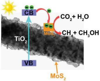 | ‡ | [50] |
| 0.5 wt% MoS2/TiO2 | Hydrothermal method | 200 mL of 1 M NaHCO3 solution and pure CO2 | 300 W Xenon arc lamp. | airtight quartz glass reactor Photocatalyst concentration in 0.5 g L−1 | CH3OH = 10.6 μmol g−1 h−1 | - | [51] | |
| Photocatalysts | CO2 Photoreduction Condition | Yield of Products | Type of Heterojunction | Ref. | ||||
|---|---|---|---|---|---|---|---|---|
| Type | Prepared | Reaction Mixture | Light Source | Conditions | ||||
| 1:10 GaP/TiO2 | Mechanically milling of Commercial TiO2 Evonik P25 and GaP Aldrich powders | CO2 and water | 1500 W high pressure Xe lamp | gas–solid Pyrex batch photoreactor of cylindrical shape (V = 100 mL, Φ = 94 mm, height = 15 mm) Photocatalyst concentration in 3 g L−1 | CH4 = 118.18 μM g−1 after 10 h | Z-scheme  | * | [52] |
| 20% FeTiO3/TiO2 | Hydrothermal method | 30 mL distilled water containing sodium bicarbonate (NaHCO3, 0.08 M) | 500 W high-pressure Xe lamp. A Pyrex glass tube cut off light with λ < 300 nm and a 2 M NaNO2 solution was applied to cut off λ < 400 nm | quartz reaction vessel, connected to a gas chromatograph. Photocatalyst concentration in 1.7 g L−1 | CH3OH = 0.462 μmol g−1 h−1 under UV-vis irradiation and CH3OH = 0.432 μmol g−1 h−1 under visible light irradiation. | - | - | [53] |
| 13.4% CaTiO3/TiO2 | In situ hydrothermal method | CO2 and water | 300 W Xe lamp | Quartz tube reactor, with 43 mL volume Photocatalyst concentration in 0.23 g L−1 | CO = 11.72 μmol g−1 h−1 | Z-scheme  | ‡ | [54] |
Publisher’s Note: MDPI stays neutral with regard to jurisdictional claims in published maps and institutional affiliations. |
© 2022 by the authors. Licensee MDPI, Basel, Switzerland. This article is an open access article distributed under the terms and conditions of the Creative Commons Attribution (CC BY) license (https://creativecommons.org/licenses/by/4.0/).
Share and Cite
Barrocas, B.T.; Ambrožová, N.; Kočí, K. Photocatalytic Reduction of Carbon Dioxide on TiO2 Heterojunction Photocatalysts—A Review. Materials 2022, 15, 967. https://doi.org/10.3390/ma15030967
Barrocas BT, Ambrožová N, Kočí K. Photocatalytic Reduction of Carbon Dioxide on TiO2 Heterojunction Photocatalysts—A Review. Materials. 2022; 15(3):967. https://doi.org/10.3390/ma15030967
Chicago/Turabian StyleBarrocas, Beatriz Trindade, Nela Ambrožová, and Kamila Kočí. 2022. "Photocatalytic Reduction of Carbon Dioxide on TiO2 Heterojunction Photocatalysts—A Review" Materials 15, no. 3: 967. https://doi.org/10.3390/ma15030967
APA StyleBarrocas, B. T., Ambrožová, N., & Kočí, K. (2022). Photocatalytic Reduction of Carbon Dioxide on TiO2 Heterojunction Photocatalysts—A Review. Materials, 15(3), 967. https://doi.org/10.3390/ma15030967