
Sintering Nano-Silver Paste by Resistive Joule Heating Process for 2G HTS Tape Joints


Abstract
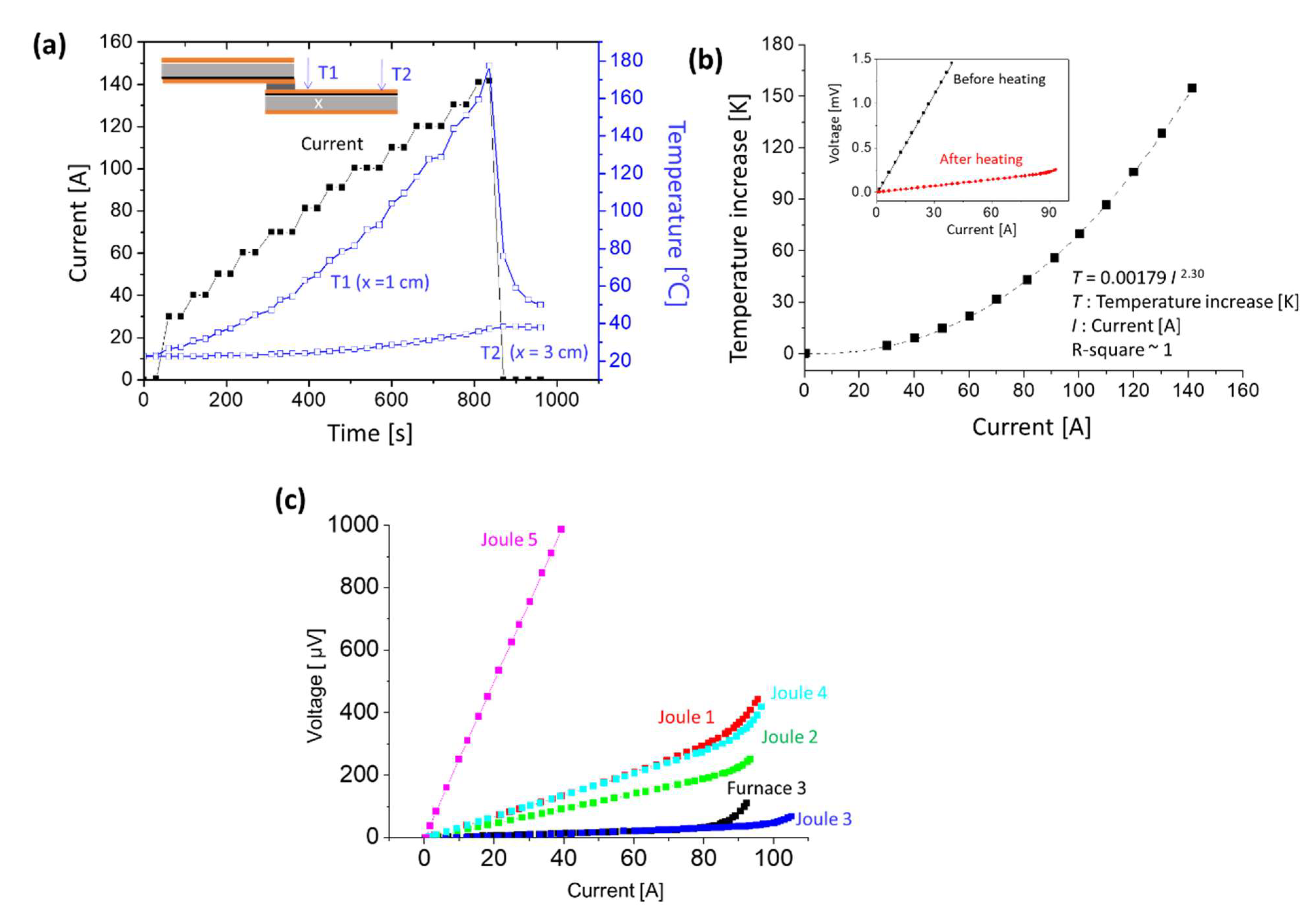
:
1. Introduction
2. Materials and Methods
2.1. Preparation of Tape-to-Tape Joints
2.2. Heat Treatment of the Tape-Solder (Nano-Silver Paste)-Tape Joint Sample
2.3. Analysis
3. Results
3.1. The Furnace Heating Process
3.2. The Resistive Joule Heating Process
4. Discussion
5. Conclusions
Author Contributions
Funding
Data Availability Statement
Conflicts of Interest
References
- Lvovsky, Y.; Stautner, E.W.; Zhang, T. Novel technologies and configurations of superconducting magnets for MRI. Supercond. Sci. Technol. 2013, 26, 093001. [Google Scholar] [CrossRef]
- Yanagisawa, Y.; Piao, R.; Iguchi, S.; Nakagome, H.; Takao, T.; Kominato, K.; Hamada, M.; Matsumoto, S.; Suematsu, H.; Jin, X. Operation of a 400 MHz NMR magnet using a (RE: Rare earth) Ba2Cu3O7− x high-temperature superconducting coil: Towards an ultra-compact super-high field NMR spectrometer operated beyond 1 GHz. J. Magn. Reson. 2014, 249, 38–48. [Google Scholar] [CrossRef] [PubMed] [Green Version]
- Uglietti, D. A review of commercial high temperature superconducting materials for large magnets: From wires and tapes to cables and conductors. Supercond. Sci. Technol. 2019, 32, 053001. [Google Scholar] [CrossRef]
- Martucciello, N.; Giubileo, F.; Grimaldi, G.; Corato, V. Introduction to the focus on superconductivity for energy. Supercond. Sci. Technol. 2015, 28, 070201. [Google Scholar] [CrossRef]
- Selvamanickam, V.; Chen, Y.; Xiong, X.; Xie, Y.; Zhang, X.; Rar, A.; Martchevskii, M.; Schmidt, R.; Lenseth, K.; Herrin, J. Progress in second-generation HTS wire development and manufacturing. Phys. C Supercond. 2008, 468, 1504–1509. [Google Scholar] [CrossRef]
- Larbalestier, D.; Gurevich, A.; Feldmann, D.M.; Polyanskii, A. High-Tc superconducting materials for electric power applications. Mater. Sustain. Energy A Collect. Peer-Rev. Res. Rev. Artic. Nat. Publ. Group 2011, 311–320. [Google Scholar] [CrossRef]
- Gurevich, A. To use or not to use cool superconductors? Nat. Mater. 2011, 10, 255–259. [Google Scholar] [CrossRef] [Green Version]
- Tsui, Y.; Surrey, E.; Hampshire, D. Soldered joints—an essential component of demountable high temperature superconducting fusion magnets. Supercond. Sci. Technol. 2016, 29, 075005. [Google Scholar] [CrossRef]
- Huang, D.; Gu, H.; Dong, Z.; Shang, H.; Xu, W.; Li, T.; Xie, B.; Zhang, H.; Ding, F. Study on electromechanical properties of solder jointed YBCO coated conductors with etched copper stabilizer under axial tension. IEEE Trans. Appl. Supercond. 2019, 30, 8400106. [Google Scholar] [CrossRef]
- Balashov, N.N.; Degtyarenko, P.N.; Ivanov, S.S.; Kopylov, S.I.; Gorbunova, D.A.; Molodyk, A.A.; Samoilenkov, S.V.; Sytnikov, V.E.; Zheltov, V.V. Low-resistance soldered joints of commercial 2G HTS wire prepared at various values of applied pressure. IEEE Trans. Appl. Supercond. 2018, 28, 6602604. [Google Scholar] [CrossRef]
- Nishio, T.; Ito, S.; Hashizume, H. Heating and loading process improvement for indium inserted mechanical lap joint of REBCO tapes. IEEE Trans. Appl. Supercond. 2017, 27, 4603305. [Google Scholar] [CrossRef]
- Ito, S.; Fujii, H.T.; Hayasaka, R.; Sato, Y.S.; Hashizume, H. Comparison of heat assisted lap joints of high-temperature superconducting tapes with inserted indium foils. IEEE Trans. Appl. Supercond. 2019, 29, 6600405. [Google Scholar] [CrossRef]
- Nakanishi, T.; Machi, T.; Izumi, T.; Teranishi, R.; Kato, T.; Kato, T.; Hirayama, T. Jointing of coated conductors by using nano-particle metal pastes. Phys. Procedia 2016, 81, 105–108. [Google Scholar] [CrossRef] [Green Version]
- Kato, J.; Sakai, N.; Miyata, S.; Konishi, M.; Yamada, Y.; Chikumoto, N.; Nakao, K.; Izumi, T.; Shiohara, Y. Optimization of the diffusion joint process for the Ag layers of YBCO coated conductors. Phys. C Supercond. Its Appl. 2007, 463, 747–750. [Google Scholar] [CrossRef]
- Kato, J.; Sakai, N.; Miyata, S.; Ibi, A.; Sutoh, Y.; Yamada, Y.; Chikumoto, N.; Nakao, K.; Izumi, T.; Shiohara, Y. Diffusion joint using silver layer of YBCO coated conductors for applications. Phys. C Supercond. 2008, 468, 1571–1574. [Google Scholar] [CrossRef]
- Park, Y.; Lee, M.; Ann, H.; Choi, Y.H.; Lee, H. A superconducting joint for GdBa2Cu3O7− δ-coated conductors. NPG Asia Mater. 2014, 6, e98. [Google Scholar] [CrossRef]
- Jin, X.; Yanagisawa, Y.; Maeda, H.; Takano, Y. Development of a superconducting joint between a GdBa2Cu3O7-δ-coated conductor and YBa2Cu3O7− δ bulk: Towards a superconducting joint between RE (Rare Earth) Ba2Cu3O7− δ-coated conductors. Supercond. Sci. Technol. 2015, 28, 075010. [Google Scholar] [CrossRef]
- Jin, X.; Yanagisawa, Y.; Maeda, H. Measurement of persistent current in a Gd123 coil with a superconducting joint fabricated by the CJMB method. IEEE Trans. Appl. Supercond. 2018, 28, 4602604. [Google Scholar] [CrossRef]
- Ohki, K.; Nagaishi, T.; Kato, T.; Yokoe, D.; Hirayama, T.; Ikuhara, Y.; Ueno, T.; Yamagishi, K.; Takao, T.; Piao, R. Fabrication, microstructure and persistent current measurement of an intermediate grown superconducting (iGS) joint between REBCO-coated conductors. Supercond. Sci. Technol. 2017, 30, 115017. [Google Scholar] [CrossRef]
- Yazaki, S.; Karasawa, A.; Kotoyori, T.; Ishiyama, A.; Miyahara, N. Critical current degradation in high-temperature superconducting tapes caused by temperature rise. IEEE Trans. Appl. Supercond. 2013, 23, 4602304. [Google Scholar] [CrossRef]
- Preuss, A.; Fietz, W.H.; Immel, F.; Kauffmann-Weiss, S.; Wolf, M.J. Critical current degradation of coated conductors under soldering conditions. IEEE Trans. Appl. Supercond. 2018, 28, 6601105. [Google Scholar] [CrossRef]
- Mei, Y.; Chen, G.; Cao, Y.; Li, X.; Han, D.; Chen, X. Simplification of low-temperature sintering nanosilver for power electronics packaging. J. Electron. Mater. 2013, 42, 1209–1218. [Google Scholar] [CrossRef]
- Mei, Y.; Li, L.; Li, X.; Li, W.; Yan, H.; Xie, Y. Electric-current-assisted sintering of nanosilver paste for copper bonding. J. Mater. Sci. : Mater. Electron. 2017, 28, 9155–9166. [Google Scholar] [CrossRef]
- Mei, Y.-H.; Cao, Y.; Chen, G.; Li, X.; Lu, G.-Q.; Chen, X. Characterization and reliability of sintered nanosilver joints by a rapid current-assisted method for power electronics packaging. IEEE Trans. Device Mater. Reliab. 2013, 14, 262–267. [Google Scholar] [CrossRef]
- Kim, Y.-J.; Park, B.-H.; Hyun, S.-K.; Nishikawa, H. The influence of porosity and pore shape on the thermal conductivity of silver sintered joint for die attach. Mater. Today Commun. 2021, 29, 102772. [Google Scholar] [CrossRef]
- Hsu, S.L.-C.; Chen, Y.-T.; Chen, M.-L.; Chen, I.-G. Low Sintering Temperature Nano-Silver Pastes with High Bonding Strength by Adding Silver 2-Ethylhexanoate. Materials 2021, 14, 5941. [Google Scholar] [CrossRef]
- Skarba, M.; Pekarčíková, M.; Frolek, L.; Cuninková, E.; Necpal, M. Thermal Cycling of (RE) BCO-Based Superconducting Tapes Joined by Lead-Free Solders. Materials 2021, 14, 1052. [Google Scholar] [CrossRef]
- Ito, S.; Tamura, H.; Yanagi, N.; Hashizume, H. Low-resistance joint development for segment-fabrication of high-temperature superconducting fusion magnets. Nucl. Fusion 2021, 61, 115002. [Google Scholar] [CrossRef]
- Murtomäki, J.S.; Kirby, G.; van Nugteren, J.; Contat, P.-A.; Sacristan-de-Frutos, O.; Fleiter, J.; Pincot, F.-O.; de Rijk, G.; Rossi, L.; Ruuskanen, J. 10 kA joints for HTS Roebel cables. IEEE Trans. Appl. Supercond. 2018, 28, 4801406. [Google Scholar] [CrossRef]
- Gao, S.; Yang, Z.; Tan, Y.; Li, X.; Chen, X.; Sun, Z.; Lu, G.-Q. Bonding of large substrates by silver sintering and characterization of the interface thermal resistance. IEEE Trans. Ind. Appl. 2018, 55, 1828–1834. [Google Scholar] [CrossRef]
- Dai, J.; Li, J.; Agyakwa, P.; Corfield, M.; Johnson, C.M. Comparative thermal and structural characterization of sintered nano-silver and high-lead solder die attachments during power cycling. IEEE Trans. Device Mater. Reliab. 2018, 18, 256–265. [Google Scholar] [CrossRef]
- Lee, T.; Choi, W.; Tu, K.-N.; Jang, J.; Kuo, S.; Lin, J.; Frear, D.; Zeng, K.; Kivilahti, J. Morphology, kinetics, and thermodynamics of solid-state aging of eutectic SnPb and Pb-free solders (Sn–3.5 Ag, Sn–3.8 Ag–0.7 Cu and Sn–0.7 Cu) on Cu. J. Mater. Res. 2002, 17, 291–301. [Google Scholar] [CrossRef]
- Michalcová, E.; Gömöry, F.; Frolek, L.; Drienovský, M.; Pekarčíková, M.; Skarba, M.; Mišík, J.; Janovec, J. Joining of CC tapes with lead-free solders. IEEE Trans. Appl. Supercond. 2016, 26, 8801104. [Google Scholar] [CrossRef]


| Process | Sample Name | Heating Temperature (°C) | Ic Before Joining (A) | Ic After Joining (A) | Ic Retention Percentage | Specific Resistance (μΩ∙cm2) |
|---|---|---|---|---|---|---|
| Furnace Heating Sample | Furnace 1 | 180 | 99.4 | − | − | 948 |
| Furnace 2 | 200 | 90.6 | 83.2 | 92% | 1.03 | |
| Furnace 3 | 215 | 97.5 | 83.2 | 85% | 0.21 | |
| Furnace 4 | 230 | 94.5 | 69.9 | 72% | 0.20 | |
| Furnace 5 | 250 | 97.6 | 42.7 | 44% | 0.29 | |
| Resistive Joule Heating Sample | Joule 1 | 103 | 92.5 | 77.6 | 84% | 0.697 |
| Joule 2 | 116.2 | 89.4 | 87.8 | 98% | 0.468 | |
| Joule 3 | 156 | 101.3 | 100.0 | 99% | 0.054~0.074 | |
| Joule 4 | 177.4 | 91.8 | 86.6 | 94% | 0.686 | |
| Joule 5 | 228.6 | 86.9 | 78.0 | 90% | 15.0 |
| Solder Material | Heating Temperature | Specific Resistance | Reference |
|---|---|---|---|
| Sn36Pb37 | 190 °C | 0.025~0.027 μΩ·cm2 | [9] |
| Pb39Sn61 | 200 °C (Lamination joint) | 0.010~0.015 μΩ·cm2 | [10] |
| In | 90~140 °C | ~0.025 μΩ·cm2 | [11] |
| In | Ultrasonic welding | 0.031~0.032 μΩ·cm2 | [12] |
| Sn96.5Ag3Cu0.5 | 226~233 °C | 0.067~0.070 μΩ·cm2 | [33] |
| Nano metal paste | 150~200 °C | ~0.048 μΩ·cm2 | [13] |
| Nano-silver paste | 150~200 °C | 0.054~15 μΩ·cm2 | this study |
Publisher’s Note: MDPI stays neutral with regard to jurisdictional claims in published maps and institutional affiliations. |
© 2022 by the authors. Licensee MDPI, Basel, Switzerland. This article is an open access article distributed under the terms and conditions of the Creative Commons Attribution (CC BY) license (https://creativecommons.org/licenses/by/4.0/).
Share and Cite
Yang, C.-M.; Chang, Y.-C.; Chang, C.-L.; Chen, I.-G. Sintering Nano-Silver Paste by Resistive Joule Heating Process for 2G HTS Tape Joints. Materials 2022, 15, 1571. https://doi.org/10.3390/ma15041571
Yang C-M, Chang Y-C, Chang C-L, Chen I-G. Sintering Nano-Silver Paste by Resistive Joule Heating Process for 2G HTS Tape Joints. Materials. 2022; 15(4):1571. https://doi.org/10.3390/ma15041571
Chicago/Turabian StyleYang, Chia-Ming, Yu-Chuan Chang, Chi-Lei Chang, and In-Gann Chen. 2022. "Sintering Nano-Silver Paste by Resistive Joule Heating Process for 2G HTS Tape Joints" Materials 15, no. 4: 1571. https://doi.org/10.3390/ma15041571
APA StyleYang, C.-M., Chang, Y.-C., Chang, C.-L., & Chen, I.-G. (2022). Sintering Nano-Silver Paste by Resistive Joule Heating Process for 2G HTS Tape Joints. Materials, 15(4), 1571. https://doi.org/10.3390/ma15041571