Article

Effect of Nano-Y2O3 on the Microstructure and Properties of WC-Reinforced Ni-Based Composite Surfacing Layer

Department of Material Science and Engineering, Shenyang University of Technology, Shenyang 110870, China
*
Author to whom correspondence should be addressed.
Materials 2022, 15(5), 1665; https://doi.org/10.3390/ma15051665
Submission received: 11 January 2022 / Revised: 1 February 2022 / Accepted: 4 February 2022 / Published: 23 February 2022

Abstract

:
In this study, a WC-reinforced Ni-based surfacing layer was prepared on Q235 steel plate by plasma arc welding. The effects of nano-Y2O3 with different contents (0 wt.%, 0.4 wt.%, 0.8 wt.%, 1.2 wt.%, and 1.6 wt.%) on the microstructure, phase composition, microhardness, and wear resistance of the surfacing layer were studied by scanning electron microscope (SEM), energy dispersive spectrometer (EDS), X-ray diffraction (XRD), microhardness test, and pin-on-disk test. The results show that the phase composition of the surfacing layer was γ-Ni, FeNi3 solid solution, WC, W2C, M23C6, M6C, Cr7C3, and other carbides. When the addition of nano-Y2O3 was 1.2 wt.%, it has a good improvement on microstructure grain refinement and carbide hard-phase increase. Compared with other contents, 1.2 wt.% nano-Y2O3 surfacing layer has the highest microhardness and the lowest friction coefficient and wear loss. At this time, the wear mechanism is abrasive wear accompanied by slight adhesive wear.

1. Introduction

Wear is one of the common failure modes of mechanical parts, and traditional steel materials find increasing difficulty in meeting the demands of special environments [1]. To improve the service life of components, surface engineering techniques are widely used in engineering practice [2,3,4]. Surfacing a wear-resistant layer on components is the most common means, which is of great significance for the safe use of workpieces. Currently, metal matrix composites (MMCs), which can combine the advantages of ceramic and metal materials, are widely used in material surface cladding technology. MMCs are composites based on metals, metal alloys, and intermetallic compounds, which are obtained by adding high-performance reinforcing fibers [5,6], whiskers and particles [7,8], or by the reaction to form reinforcing phases. Metal matrix composites have high strength, stiffness, good thermal stability, wear resistance, creep resistance, and good dimensional stability [9]. At present, the matrix used in MMCs includes the iron matrix, titanium matrix, nickel matrix, etc. [10,11]. Among them, nickel matrix self-melting alloy powder has excellent comprehensive properties and can greatly improve the surface properties of materials [12,13,14,15].
The addition of some ceramic particles to the nickel-based powder enables the surfacing layer to achieve higher hardness, wear resistance, corrosion resistance, etc. [16,17]. WC is a hard phase commonly used in MMCs. WC powder has a high melting point, high hardness, good wear resistance, and good wettability with MMCs. Therefore, WC reinforced nickel-based alloy surfacing layer has been widely used [18,19,20,21]. Acker K V et al. [22] prepared WC/W2C carbide-reinforced nickel-based coatings by laser cladding. The results show that both the increase in carbide concentration and the decrease in size are beneficial for wear resistance. Kwon H et al. [23] prepared highly toughened TiC-Ni type cermet using nano-TiC and WC powders. The data show that enhanced toughness is due to solid–solution strengthening of the carbide phase, combined with WC whisker reinforcement.
It is generally believed that rare earth elements have an elemental activity effect, which can segregate impurity elements in the surfacing layer to the grain boundary, inhibit the growth of columnar crystals, refine the microstructure and strengthen the wear resistance of the surfacing layer. The addition of rare earth elements in the surfacing layer can also improve the fluidity and wettability of metal-based composite powder, eliminate defects such as pores, and improve the macro formability of weld. Therefore, the application of rare earth particles to modify the surfacing layer has become a hot spot for current research [13,24,25,26]. Lin et al. [27] found that the optimal addition of Y2O3 promoted the formation of TiC and TiSi2 hard phases, thus improving the microhardness and wear resistance of the cladding layer. Zhao et al. [28] prepared nickel-based coatings with nanoscale La2O3 by laser melting and found that the addition of La2O3 significantly refined γ- (Ni, Fe) dendrites, improving the hardness and wear properties of the coatings. Wang et al. [29,30] investigated the microstructural characteristics of laser clad nickel-based alloy coatings with rare earth oxide CeO2 or La2O3. The results show that the microstructure is refined and the wear resistance and corrosion resistance are enhanced after adding rare earth oxide. Li et al. [31] prepared TiB/TiC-reinforced titanium matrix composite coatings on Ti6Al4V substrates by laser melting. It was shown that the addition of Y2O3 played a positive role in the wear resistance of the coatings. Yun et al. [32] investigated the effect of different Y2O3 additives on the wear resistance of hypereutectic Fe-Cr-C hardfacing coatings. The results showed that Y2O3 could refine the M7C3 carbide and significantly improve the wear resistance of the coatings. In this paper, nano-Y2O3 modified nickel-based WC surfacing layers with different contents were prepared on Q235 steel plate by plasma surfacing technology. The effects of nano-Y2O3 content on macromorphology, microstructure, microhardness, and wear properties of the nickel-based WC (30%) surfacing layer were studied.

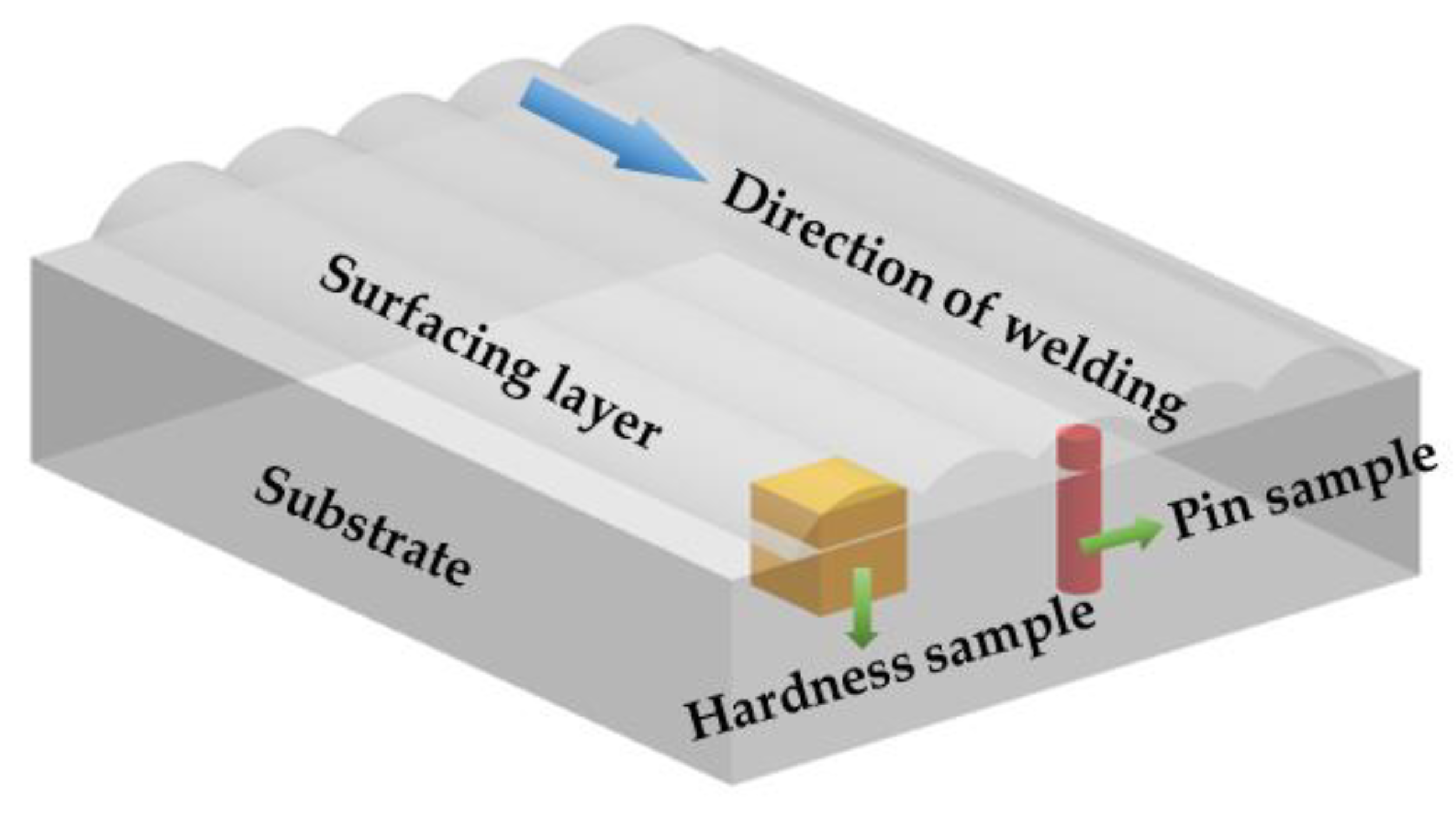
2. Materials and Methods

Q235 mild steel was used as the substrate in the present study, which was cut to a dimension of 100 mm × 80 mm × 20 mm by WEDM (Wire Electrical Discharge Machining), and the chemical composition of Q235 is shown in Table 1. Three powders used in the study are spherical Ni60 (150–300 mesh), rhombic WC with 99.9% purity (100–300 mesh), and spherical Y2O3 with 99.9% purity (Nanoscale). The chemical composition of Ni60 is shown in Table 2, and the morphologies of the three powders are shown in Figure 1.
Before the test, the oxide scale of the substrate was removed with an angle grinder, then the oil stain was removed with acetone, and finally the substrate was sandblasted. Y2O3 measuring 0 wt.%, 0.4 wt.%, 0.8 wt.%, 1.2 wt.% and 1.6 wt.% was mixed with 30% WC-Ni60 powder by a powder blender. Five different powders were milled by planetary muller for two hours, and the milled powder was placed into a 150 ℃ drying oven for two hours. A plasma surfacing equipment (BX-ZH-400A) was applied for surface overlaying. A schematic diagram of welding equipment is shown in Figure 2. In the present study, the welding current is 120A, the welding speed is 100 mm/min, the powder feeding speed is 15 g/min, the plasma gas flow rate is 4 L/min, the shielding gas flow rate is 10 L/min, and the distance between the nozzle and substrate is 12 mm.
S-3400N scanning electron microscope was used to observe the microstructure of the surfacing layer and the wear morphology of the specimens after wear. Xrd-7000 X-ray diffractometer was used to analyze the phase of surfacing layer, and the Cu-kα radial was selected with a working voltage of 40 KV, working current of 30 mA, scanning speed of was 2°/min, and scanning range was 20° to 90°. The Vickers hardness of the surfacing layer was tested by HVS-5 Vickers hardness tester, and the test load was 0.5 kg and the loading time was 15 s. Bearings, gears, sliders, and valves are the most susceptible to wear among mechanical components, and about 80% of the components in the use of mechanical equipment are invalid due to wear [33]. In this experiment, the pin-on-disk wear test is used to simulate metal-to-metal wear under actual working conditions. Friction wear testing machine was used to test the wear resistance of the specimens. The specimen was made into a φ4 × 15 mm round bar, and the thickness of the wear-resistant surfacing layer on the top of the pin is 5 mm. The GCr15 (High-carbon chromium bearing steel) disc with a hardness of 61HRC after quenching and tempering was selected for the grinding pair, and the surface roughness is Ra = 0.8; the chemical composition of GCr15 is shown in Table 3, and the schematic diagram of the pin-on-disc wear and the specimen size is shown in Figure 3. The parameters of the pin-on-disc wear test were as follows: loading force 300 N, rotating speed 100 r/min, time 30 min, and temperature 400 ℃. The wear specimen was weighed before and after the test, and the friction coefficient of the specimen was recorded by the sensor connected with the computer. The sampling positions of the Vickers hardness test and the pin-on-disc wear test are shown in Figure 4.

3. Results and Discussion

3.1. Effect of Y2O3 Content on the Formability of Surfacing Layer

Figure 5 shows the macromorphology of the surfacing layer with different content of Y2O3. (a 0 wt.%, b 0.4 wt.%, c 0.8 wt.%, d 1.2 wt.%, and e 1.6 wt.%). It can be seen from the figure that as the amount of Y2O3 added increases from 0 wt.% to 1.2 wt.%, the surface morphology of the surfacing layer gradually becomes flat and smooth, the spatter rate decreases, and the powder can be completely melted. When the amount of Y2O3 was added to 1.6 wt.%, the surface of the surfacing layer began to have wrinkles, pores, and cracks appear and they formed poorly, indicating that the right amount of Y2O3 can obtain a well-formed surfacing layer.
Figure 6 shows the cross-sectional shape of the surfacing layer perpendicular to the welding direction in which Y2O3 content is 0 wt.%, 0.4 wt.%, 0.8 wt.%, 1.2 wt.%, and 1.6 wt.%, respectively. It can be seen from the figure that with the increase in Y2O3 content, the wetting angle decreases first and then increases.
Wetting refers to the process in which one fluid on the surface of the solid is replaced by another fluid. As shown in Figure 7, basic wetting can be expressed by the young Dupre equation as follows [34].
cos θ = ( σ s g σ s l ) / σ l g
The smaller the wetting angle θ, the better the wettability. Wettability depends on the surface tension of solid σsg, solid–liquid interfacial tension σsl, and liquid surface tension σlg with respect to the magnitude of these three forces. For liquids, the lower the surface tension, the better the wettability [35,36]. The reason is that Y2O3 is added to the deposited metal as an oxide dispersed particle. The conductivity and thermal conductivity of the deposited metal decrease with the increase in Y2O3 content so as to reduce the surface tension of the molten pool metal and reduce the wetting angle, indicating that wettability between the molten pool metal and the base metal will be improved, Therefore, an appropriate amount of Y2O3 can obtain a surfacing layer with good forming quality.

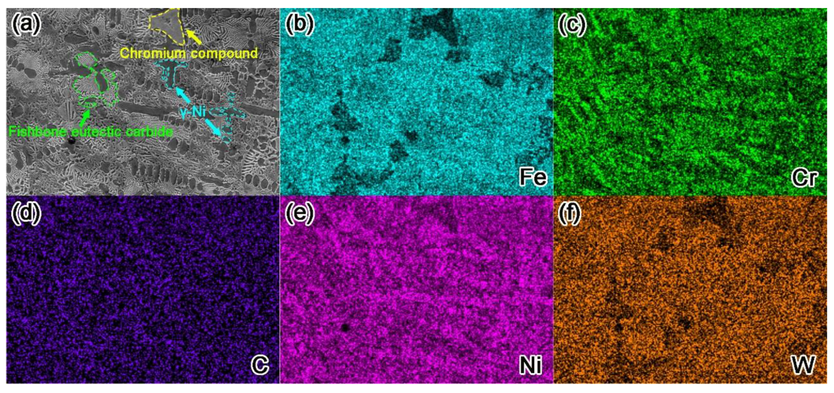
3.2. Analysis of Phase and Microstructure

In order to understand the effect of different content of nano-Y2O3 on the phase evolution of the surfacing layer, the surface of the surfacing layer was analyzed by X-ray diffraction. As can be seen from Figure 8, the main diffraction peak is γ-Ni (Fe), indicating that the γ-Ni (Fe) solid solution is the matrix phase of the surfacing layer. An XRD spectrum shows that carbides such as WC, W2C, M23C6, M6C, Cr7C3, and FeNi3 compounds also exist in the surfacing layer. Overall, the presence or absence of Y2O3 has a small effect on the phase composition of the surfacing layer, but it can be observed that with the addition of nano-Y2O3, the peak strength of carbide increases. This is because nano-Y2O3 does not change the phase composition, but will act as heterogeneous nuclear particles to promote the formation of carbide [37].
Figure 9 shows scanning electron microscope (SEM) and energy dispersive spectrometer (EDS) images of nano-Y2O3 modified surfacing layers with different contents. It can be observed from the figure that the microstructure of the surfacing layer is composed of dendrites and eutectic compounds. Combined with EDS and X-ray diffraction (XRD) analysis, region A contains M6C carbide, region B contains composite carbide with WC, W2C, region C is mainly primary dendrites γ-Ni, region D comprises gray-white particles, and the main elements are W and C and the atomic ratio ≈ 1:1. It can be judged that granular matter is unfused WC.
When the addition of Y2O3 is 0.4 wt.%, the microstructure of the surfacing layer begins to change, and white lamellar eutectic carbide can be observed to begin to appear, with more grey eutectic tissue around it. When Y2O3 content increases to 0.8 wt.%, the distribution of microstructure is relatively dense, the white eutectic carbides around unfused WC increase obviously, and a large number of dendrites are gathered around these carbides. By observing WC in Figure 9e, it can be observed that there is a gray–white area in the center of the WC, which is called the core area. In the periphery of WC, there is a silvery gray area with a thickness of about 3 um, which is called the melting diffusion area. According to the relevant carbide melting mechanism [38], when WC particles enter the melting pool, the outer layer of larger particles melts under the action of high-temperature plasma arc and attaches around the core area. With the addition of nano Y2O3 reaching 1.2 wt.%, as the core of heterogeneous nucleation [37], lamellar eutectic carbides begin to increase, and these eutectic carbides attach to the unfused WC core area and grow around it. Although the presence of Y was not detected in XRD analysis, a small amount of Y was found in EDS analysis.
Studies have shown that high melting point rare nano-Y2O3 has difficulty in completely melting in the process of plasma surfacing, and the incompletely melted Y2O3 powder in the surfacing layer will more easily become the core of heterogeneous phase nucleation, which is conducive to improving nucleation rates and promoting nonspontaneous nucleation so as to refine grains [39]. In this study, only the addition of Y2O3 was changed, and the content of other elements remained unchanged, but the carbides significantly increased, as seen in Figure 9, which confirmed the above view from the side, and the increased carbides were nucleated carbides. At the same time, nano-Y2O3 will decompose into Y atoms with large atomic radius and good chemical activity at high temperature, and Y atoms will gather at the grain boundary, resulting in a drag effect on the grain boundary and inhibiting grain growth [40,41]. When the amount of Y2O3 added to the surfacing layer increases to 1.6 wt.%, the microstructure is observed not to change much, but the eutectic carbides start to decrease and dendrite size increases. This is because the addition of excessive nano-Y2O3 reduces the fluidity of the molten pool, slows down the convection speed, makes it difficult to discharge inclusions and pores, reduces the cooling speed of the molten pool, and increases the size of these dendrites for a long time.
Figure 10 shows the element distribution of the microstructure of the surfacing layer. The areas with bright colors in surface scanning are the enrichment area of the element, and the areas with dark colors are the depleted area of the element. It can be observed intuitively from the figure that the dendrite region is rich in Fe, Ni, and W elements, indicating that this region is mainly composed of γ- Ni matrix phase. The massive area is mainly composed of Cr elements, with low contents of Fe, Ni, and W elements, which should be chromium compounds. The white fishbone microstructure and massive area have more Cr and C elements, and there are Ni, Fe, and W elements, indicating that the microstructure in this area is mostly carbide, which is basically consistent with the previous EDS energy spectrum analysis results.

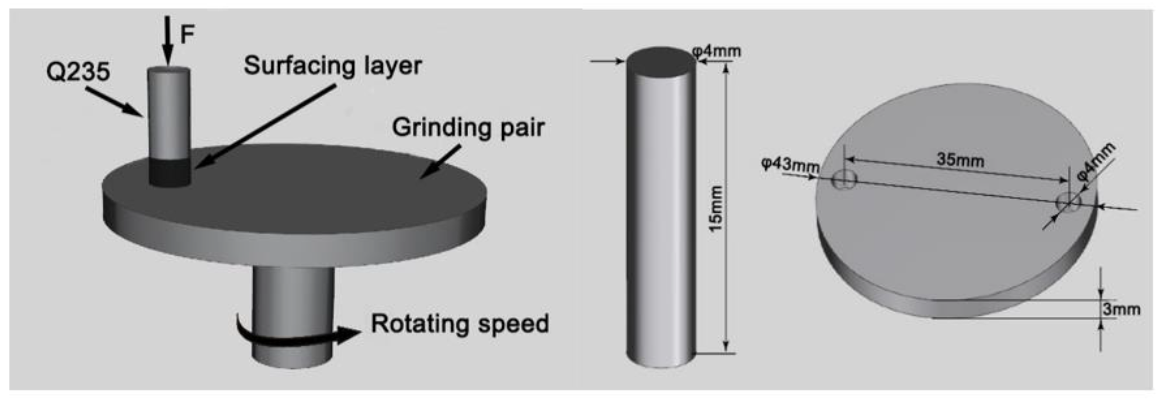
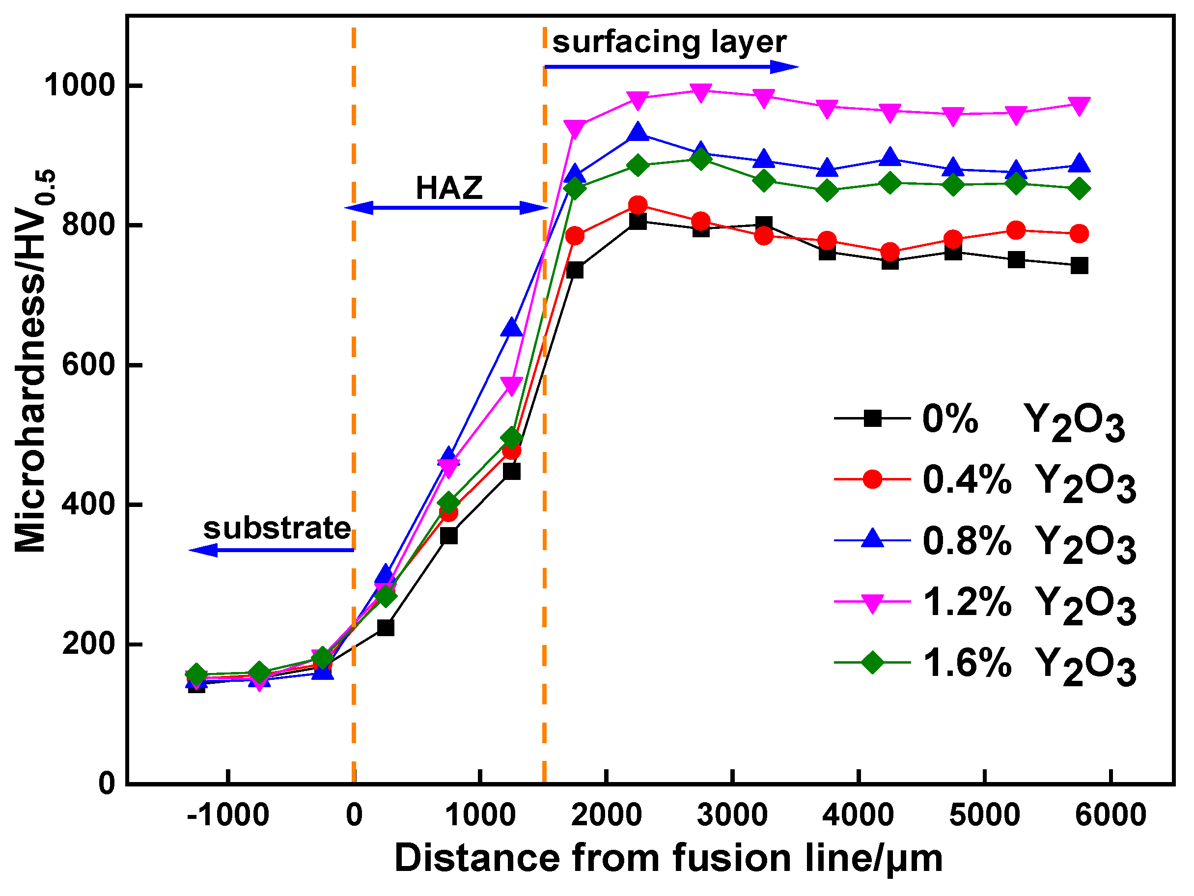
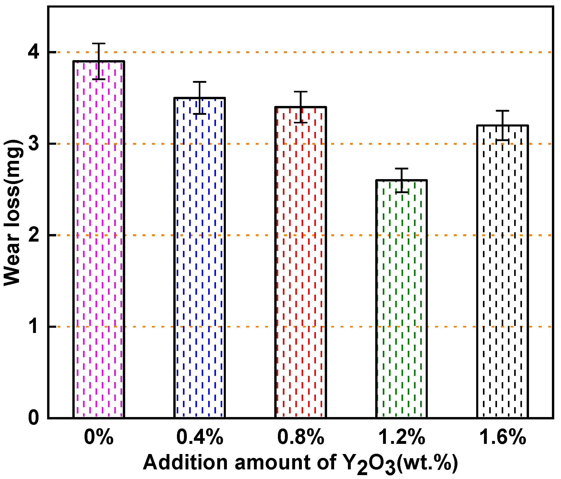
3.3. Microhardness and Wear Resistance Analysis of the Surfacing Layer

Figure 11 shows the microhardness curves of the surfacing layer with different Y2O3 content. From the figure, it can be observed that the microhardness of the surfacing layer has a significant increase compared to the base metal, while the microhardness of the heat affected zone (HAZ) is lower than that of the surfacing layer due to the dilution effect of the base metal. Compared with the surfacing layer without Y2O3, the microhardness of the surfacing layer with Y2O3 increased significantly. When the addition of Y2O3 is 0.4 wt.%, the microhardness of the surfacing layer does not increase significantly. With the addition of Y2O3 increasing to 1.2 wt.%, the average microhardness of the surfacing layer reaches the maximum, which is 970HV0.5, about 6.26 times of the base metal hardness, 283HV0.5 higher than the surfacing layer without Y2O3, and the microhardness value of each point of the surfacing layer is the most uniform under this content.
Some studies show that the transformation of hardness originates from the formation of interdendritic carbides and eutectic structures [42]. Corresponding to Figure 9, it can be observed that the addition of Y2O3 promotes a uniform dispersion of carbides in the surfacing layer during the formation process, and Y2O3 with a high melting point, as a nucleating agent, effectively refines the microstructure. Under the combined action of dispersion strengthening and fine grain strengthening, the hardness of the surfacing layer has been significantly improved. When the addition of Y2O3 is 1.6 wt.%, the microhardness of the surfacing layer decreases obviously. At this time, when Y2O3 is added excessively, the flow performance of the surfacing layer decreases, inclusions are generated in the surfacing layer, gas is difficult to escape, pores and other defects are generated, and the cooling time of the molten pool increases, which affects the microstructure of the surfacing layer so as to reduce the hardness of the surfacing layer.
Figure 12 shows the friction coefficient of the modified surfacing layer with different contents of Y2O3 at room temperature with GCr15 as a grinding pair is worn for 30 min. It can be observed from the figure that the friction coefficient of the surfacing layer modified with different content of Y2O3 varies greatly. In the initial stage of the experiment, the friction coefficient fluctuates greatly, which is caused by the machined surface roughness. Under the action of load, the contact surfaces mesh with each other. After the initial running in stage, the wear debris will fill the bonding interface, the surfacing layer will enter a stable wear stage, and the fluctuation range of the friction coefficient curve tends to be stable. After adding Y2O3, the friction coefficient of the surfacing layer decreases significantly, which can improve the wear performance of the surfacing layer. When the content of Y2O3 is 1.2 wt.%, the friction coefficient of the surfacing layer is the smallest, about 0.3092. It shows that the addition of an appropriate amount of Y2O3 can increase and evenly distribute the hard phase in the surfacing layer and form a wear-resistant skeleton on the surface of the surfacing layer, effectively improving the wear resistance of the surfacing layer. When the addition amount of Y2O3 increases to 1.6 wt.%, it can be observed that the friction coefficient begins to increase. Due to the fact that the content of Y2O3 added is too high and Y2O3 is difficult to melt, it will greatly affect the fluidity of the weld pool in the surfacing process, resulting in uneven distribution of hard phase, and the unmelted Y2O3 and other elements in the weld pool form harmful inclusions. At the same time, it may also produce defects such as pores, deteriorate the microstructure of the surfacing layer, increase the friction coefficient, and reduce the wear resistance of the surfacing layer.
Figure 13 shows the wear weight loss of the Y2O3 modified surfacing layer with different content worn for 30 min at room temperature. It can be observed that the addition of Y2O3 can improve the wear performance of the surfacing layer. With the increase in Y2O3 addition, the wear first decreases and then increases. When the addition amount of Y2O3 is 1.2 wt.% The wear performance of the surfacing layer is the best and the wear amount is the lowest, which constitutes only 2.6 mg. This indicates that the wear resistance of the Y2O3 composite surfacing layer with 1.2 wt.% addition is 1.5-times higher than that of the nickel-based tungsten carbide surfacing layer.
Figure 14 shows the wear morphology of the Y2O3 modified nickel-based tungsten carbide surfacing layer after 30 min of wear at room temperature. The surface of the surfacing layer without the addition of Y2O3 (Figure 14a) shows a large amount of fatigue delamination. With 0.4 wt.% Y2O3 (Figure 14b), a small amount of fatigue delamination is visible on the surface of the surfacing layer, and the wear mechanism is delamination wear. With the addition of 0.8 wt.% Y2O3 (Figure 14c), furrows with different depths can be observed on the surface of the surfacing layer, accompanied by a small amount of white and bright oxidized wear debris. The wear mechanism is mainly abrasive wear, accompanied by oxidative wear and adhesive wear.
After the addition of 1.2 wt.% Y2O3 (Figure 14d), furrows on the surface of the surfacing layer are shallow, the plastic deformation characteristics are not obvious, and there are still peeling pits and oxide debris caused by fatigue. This is because an appropriate amount of Y2O3 can uniformly disperse the hard phase in the surfacing layer, refine the grain, improve the ability to resist dislocation slip and promote γ- Ni matrix forms a wear-resistant skeleton with excellent wear resistance, which can effectively protect the surfacing layer from wear damage when cutting wear occurs between wear debris and matrix. After the addition of 1.6 wt.% Y2O3 (Figure 14e), adhesive wear marks and peeling pits appeared on the surface. Excessive Y2O3 will reduce the fluidity of the melt pool and the refractory Y2O3 will form inclusions with other elements in the melt pool and cause a large number of pores and other defects in the surfacing layer, resulting in a reduction in the hardness of the surfacing layer and affecting the wear performance of the surfacing layer.

4. Conclusions

In this study, the Y2O3-modified nickel-based WC surfacing layer was successfully prepared by adding nano-Y2O3. The effects of Y2O3 on the macro morphology, phase composition, microstructure, hardness, and wear resistance on the surfacing layer of the alloy have been systematically studied. The main conclusions are as follows:
  • By adding different contents of Y2O3 into the 30 wt.% WC-Ni based alloy surfacing layer, it can be observed that the addition of Y2O3 with a content of 1.2% can effectively reduce the wetting angle and improve weld formability. However, an excessive amount of Y2O3 can cause welding defects.
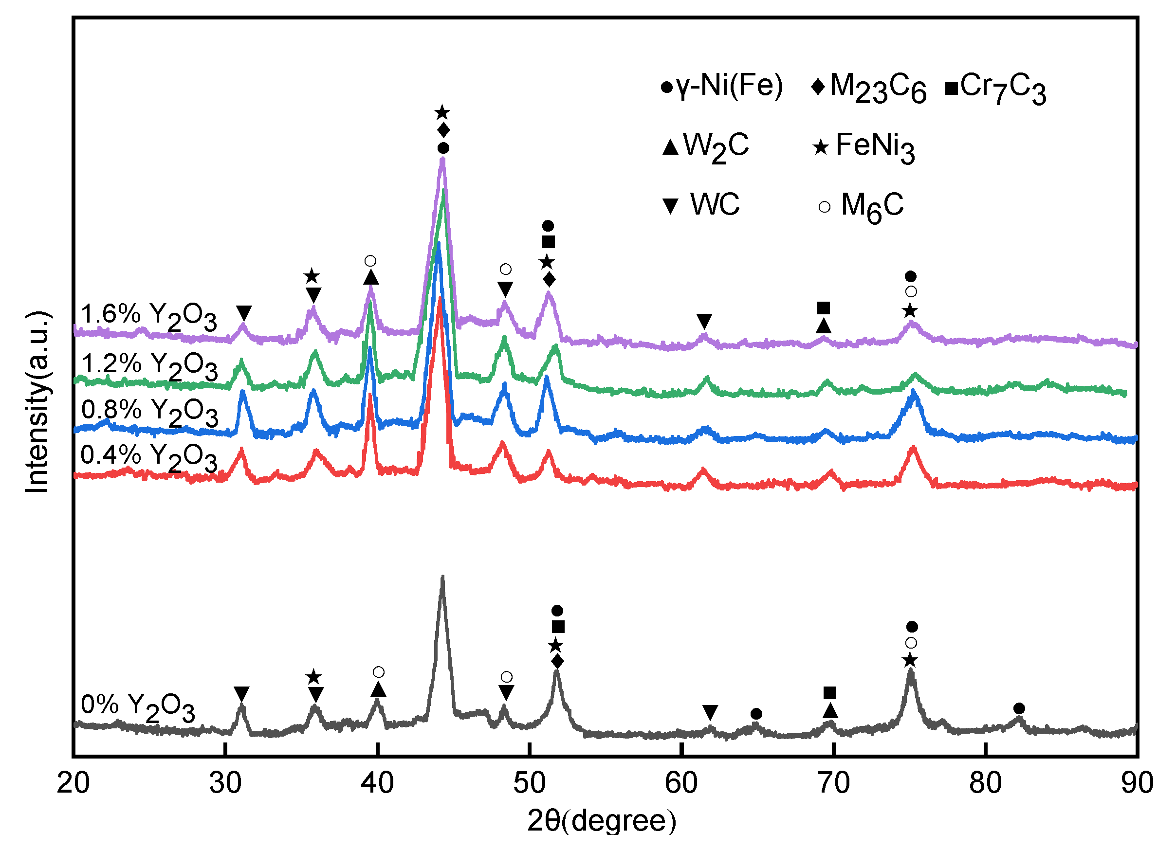
  • The formation of phase was found to be independent of the amount of RE addition, and its main phase is γ-Ni (Fe), FeNi3 solid solution. Carbides were formed with various morphology, namely, WC, W2C, M23C6, M6C, and Cr7C3.
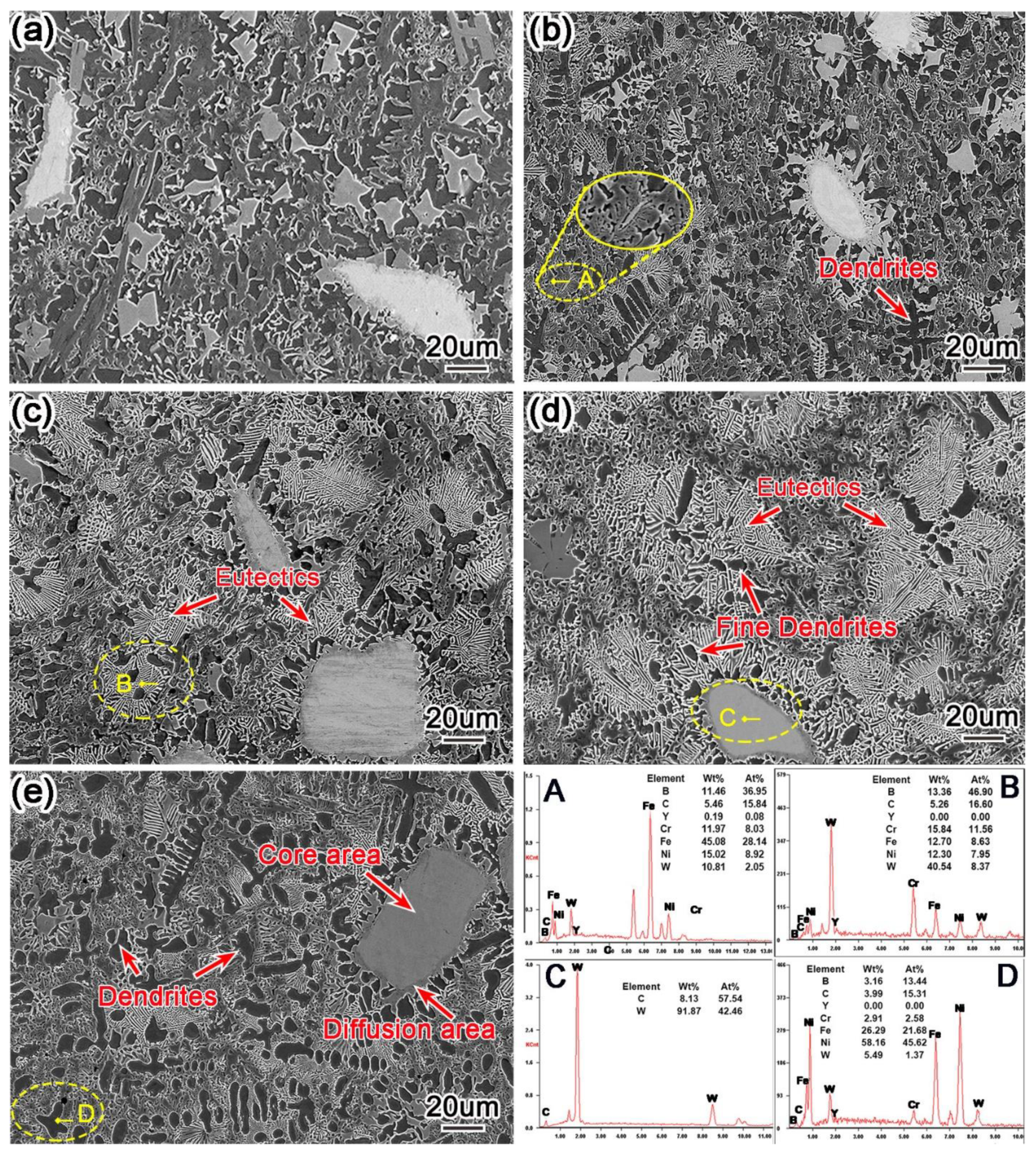
  • An appropriate amount of Y2O3 can significantly refine microstructure and increase the content of eutectic carbides. However, excessive Y2O3 will cause coarse microstructure and reduce the content of carbides.
  • The addition of nano-Y2O3 significantly improved the average hardness of the surfacing layers. With 1.2 wt.% nano-Y2O3, the surfacing layer reaches the maximum average of Vickers hardness, 970HV0.5, which is about six-times harder than the base metal.
  • According to the pin-on-disk wear experiment results, an appropriate amount of nano-Y2O3 at room temperature can reduce the coefficient of friction (COF) and wear of the surfacing layer. The minimum wear of the surfacing layer containing 1.2 wt.% nano-Y2O3 was 2.6 mg, whereas the minimum COF was approximately 0.3092. The wear mechanism is mainly abrasive wear, accompanied by slight adhesive wear.

Author Contributions

Conceptualization, X.A. and Z.L.; data curation, X.A., Z.Z. and Z.W.; investigation, X.A., Z.Z., and Z.W.; methodology, X.A., Z.L., and Z.W.; project administration, Z.L.; supervision, Z.L.; validation, X.A.; writing—original draft, X.A.; writing—review and editing, Z.L. All authors have read and agreed to the published version of the manuscript.

Funding

This research received no external funding.

Institutional Review Board Statement

Not applicable.

Informed Consent Statement

Not applicable.

Data Availability Statement

All the data and results supporting this research paper are already presented within this publication.

Conflicts of Interest

The authors declare no conflict of interest.

References

  1. Bassini, E.; Sivo, A.; Ugues, D. Assessment of the Hardening Behavior and T ensile Properties of a Cold-Rolled Bainitic–Ferritic Steel. Materials 2021, 14, 6662. [Google Scholar] [CrossRef] [PubMed]
  2. Lu, K.; Lu, J. Nanostructured surface layer on metallic materials induced by surface mechanical attrition treatment. Mater. Sci. Eng. A 2004, 375, 38–45. [Google Scholar] [CrossRef] [Green Version]
  3. Weng, F.; Yu, H.; Chen, C.; Liu, J.; Zhao, L. Microstructures and properties of TiN reinforced Co-based composite coatings modified with Y2O3 by laser cladding on Ti–6Al–4V alloy. J. Alloys Compd. 2015, 650, 178–184. [Google Scholar] [CrossRef]
  4. Yao, F.; Fang, L.; Li, G.S. Study on structure and process performance of laser cladding nickel-based coating. J. Mater. Res. Technol. 2021, 13, 138–143. [Google Scholar] [CrossRef]
  5. Chen, B.; Shen, J.; Ye, X.; Jia, L.; Li, S.; Umeda, J.; Takahashi, M.; Kondoh, K. Length Effect of Carbon Nanotubes on the Strengthening Mechanisms in Metal Matrix Composites. Acta Mater. 2017, 140, 317–325. [Google Scholar] [CrossRef]
  6. Ozerov, M.; Stepanov, N.; Kolesnikov, A.; Sokolovsky, V.; Zherebtsov, S. Brittle-to-ductile transition in a Ti–TiB metal-matrix composite. Mater. Lett. 2017, 187, 28–31. [Google Scholar] [CrossRef]
  7. Min, Y.K.; Park, J.S.; Min, K.P.; Kim, K.T.; Hong, S.H. Effect of aspect ratios of in situ formed TiB whiskers on the mechanical properties of TiBw/Ti–6Al–4V composites. Scripta 2012, 66, 487–490. [Google Scholar]
  8. Ozerov, M.S.; Klimova, M.V.; Stepanov, N.D.; Zherebtsov, S.V. Microstructure evolution of a TI/TIB metal-matrix composite during high-temperature deformation. Mater. Phys. Mech. 2018, 38, 54–63. [Google Scholar]
  9. Zherebtsov, S.; Ozerov, M.; Povolyaeva, E.; Sokolovsky, V.; Stepanov, N.; Moskovskikh, D.; Salishchev, G. Effect of Hot Rolling on the Microstructure and Mechanical Properties of a Ti-15Mo/TiB Metal-Matrix Composite. Metals-Open Access Metall. J. 2019, 10, 40. [Google Scholar] [CrossRef] [Green Version]
  10. Morsi, K. Review: Titanium–titanium boride composites. J. Mater. Sci. 2019, 54, 6753–6771. [Google Scholar] [CrossRef]
  11. Ozerov, M.; Povolyaeva, E.; Stepanov, N.; Ventzke, V.; Zherebtsov, S. Laser Beam Welding of a Ti-15Mo/TiB Metal–Matrix Composite. Metals 2021, 11, 506. [Google Scholar] [CrossRef]
  12. Marchese, G.; Bassini, E.; Parizia, S.; Manfredi, D.; Ugues, D.; Lombardi, M.; Fino, P.; Biamino, S. Role of the chemical homogenization on the microstructural and mechanical evolution of prolonged heat-treated laser powder bed fused Inconel 625-ScienceDirect. Mater. Sci. Eng. A 2020, 796, 140007. [Google Scholar] [CrossRef]
  13. He, X.; Song, R.G.; Kong, D.J. Microstructures and properties of Ni/TiC/La2O3 reinforced Al based composite coatings by laser cladding. Opt. Laser Technol. 2019, 117, 18–27. [Google Scholar] [CrossRef]
  14. Wang, X.; Keya, T.; Chou, K. Build Height Effect on the Inconel 718 Parts Fabricated by Selective Laser Melting. Procedia Manuf. 2016, 5, 1006–1017. [Google Scholar] [CrossRef] [Green Version]
  15. Zhang, K.M.; Zhou, J.; Zhang, M.M.; Peng, S.X.; Zhu, S.; Zhang, J.S. A comparison study on wear characteristics of Ni-based, Co-based and Fe-based alloys for heated hot stamping tools manufactured by surfacing technology. Int. J. Adv. Manuf. Technol. 2020, 106, 3659–3668. [Google Scholar] [CrossRef]
  16. Verma, V.; Kumar, B. Tribological characteristics of conventionally sintered TiCN-WC-Ni/Co cermets against cemented carbide. Ceram. Int. 2017, 43, 368–375. [Google Scholar] [CrossRef]
  17. Ward, L.P.; Pilkington, A. The Dry Sliding Wear Behavior of HVOF-Sprayed WC: Metal Composite Coatings. J. Mater. Eng. Perform. 2014, 23, 3266–3278. [Google Scholar] [CrossRef]
  18. Xiang, W.; Zhu, L.; Zhou, Z.; Liu, G.; Wu, X. Tribological Properties of WC-Reinforced Ni-Based Coatings Under Different Lubricating Conditions. J. Therm. Spray Technol. 2015, 24, 1323–1332. [Google Scholar]
  19. Jiménez, H.; Olaya, J.J.; Alfonso, J.E. Tribological Behavior of Ni-Based WC-Co Coatings Deposited via Spray and Fuse Technique Varying the Oxygen Flow. Adv. Tribol. 2021, 2021, 1–10. [Google Scholar] [CrossRef]
  20. Shu, D.; Li, Z.; Zhang, K.; Yao, C.; Li, D.; Dai, Z. In situ synthesized high volume fraction WC reinforced Ni-based coating by laser cladding. Mater. Lett. 2017, 195, 178–181. [Google Scholar] [CrossRef]
  21. Lv, C.; Ren, X.; Wang, C.; Peng, Z. Improved mechanical performance and wear resistance of Ti-coated cBN–WC–Ni composites. J. Mater. Res. 2019, 34, 1–9. [Google Scholar] [CrossRef]
  22. Acker, K.V.; Vanhoyweghen, D.; Persoons, R.; Vangrunderbeek, J. Influence of tungsten carbide particle size and distribution on the wear resistance of laser clad WC/Ni coatings. Wear 2005, 258, 194–202. [Google Scholar] [CrossRef]
  23. Kwon, H.; Suh, C.; Kim, W. Preparation of a highly toughened (Ti, W) C-20Ni cermet through in situ formation of solid solution and WC whiskers. Ceram. Int. 2015, 41, 4223–4226. [Google Scholar] [CrossRef]
  24. Fang, Y.C.; Cui, X.F.; Cai, Z.B.; Wang, C.; Jin, G. Influence of La2O3 addition on nano indentation hardness and residual stress of Stellite 6 coating prepared by plasma cladding. J. Rare Earth 2018, 36, 873–878. [Google Scholar] [CrossRef]
  25. Farahmand, P.; Liu, S.; Zhang, Z.; Kovacevic, R. Laser cladding assisted by induction heating of Ni–WC composite enhanced by nano-WC and La2O3. Ceram. Int. 2014, 40, 15421–15438. [Google Scholar] [CrossRef]
  26. Cui, Y. Study on the Effect of Rare Earth Elements on the Microstructure and Performance of Cladding Layer. Appl. Mech. Mater. 2014, 608, 1035–1038. [Google Scholar] [CrossRef]
  27. Lin, Y.C.; Wang, T.H. Effects of Rare Earth Y2O3 on the Microstructure and Wear Behaviors of Ti-6Al-4V Cladding with SiC. Mater. Sci. Forum 2018, 934, 89–94. [Google Scholar] [CrossRef]
  28. Zhao, N.; Tao, L.; Guo, H.; Zhang, M.Q. Microstructure and Wear Resistance of Laser Cladded Ni-based Coatings with Nanometer La2O3 Addition. Rare Metal Mater. Eng. 2017, 46, 2092–2096. [Google Scholar]
  29. Wang, K.L.; Zhang, Q.B.; Sun, M.L.; Wei, X.G. Microstructural characteristics of laser clad coatings with rare earth metal elements. J. Mater. Process. Technol. 2003, 139, 448–452. [Google Scholar] [CrossRef]
  30. Wang, K.L.; Zhang, Q.B.; Sun, M.L. Microstructure and corrosion resistance of laser clad coatings with rare earth elements. Corros. Sci. 2001, 43, 255–267. [Google Scholar] [CrossRef]
  31. Li, J.; Luo, X.; Li, G.J. Effect of Y2O3 on the Sliding Wear Resistance of TiB/TiC-Reinforced Composite Coatings Fabricated by Laser Cladding. Wear 2014, 310, 72–82. [Google Scholar] [CrossRef]
  32. Yun, X.; Zhou, Y.F.; Zhao, B.; Xing, X.L.; Yang, J.; Yang, Y.L.; Yang, Q.X. Influence of Nano-Y2O3 on Wear Resistance of Hypereutectic Fe–Cr–C Hardfacing Coating. Tribol. Lett. 2015, 58, 23. [Google Scholar] [CrossRef]
  33. Wang, J.F.; Xue, W.H.; Gao, S.Y.; Li, S.; Duan, D.L. Effect of groove surface texture on the fretting wear of Ti–6Al–4V alloy. Wear 2021, 486, 204079. [Google Scholar] [CrossRef]
  34. Lee, J.E.; Kim, K.S.; Inoue, M.; Jiang, J.X. Effects of Ag and Cu addition on microstructure properties and oxidation resistance of Sn-Zn eutectic alloy. J. Alloys Compd. 2008, 454, 310–320. [Google Scholar] [CrossRef]
  35. Chen, C.M.; Chen, C.H. Interfacial Reactions between Eutectic SnZn Solder and Bulk or Thin-Film Cu Substrates. J. Electron. Mater. 2007, 36, 1363–1371. [Google Scholar] [CrossRef]
  36. Sharif, A.; Chan, Y.C. Effect of substrate metallization on interfacial reactions and reliability of Sn-Zn-Bi solder joints. Microelectron. Eng. 2007, 84, 328–335. [Google Scholar] [CrossRef]
  37. Zhang, H.; Zou, Y.; Zeng, Z.D.; Shi, C.W. Effects of CeO2 on microstructure and corrosion resistance of TiC-VC reinforced Fe-based laser cladding layers. J. Rare Earth 2014, 32, 1095–1100. [Google Scholar] [CrossRef]
  38. Xia, M.J.; Gu, D.D.; Ma, C.L.; Zhang, H.M.; Dai, D.H.; Chen, H.Y.; Li, C.P.; Zhou, Z.J.; Chen, G.F.; Kelbassa, I. Fragmentation and refinement behavior and underlying thermodynamic mechanism of WC reinforcement during selective laser melting of Ni-based composites. J. Alloys Compd. 2018, 777, 693–702. [Google Scholar] [CrossRef]
  39. Wang, C.L.; Gao, Y.; Wang, R.; Wei, D.Q.; Cai, M.; Fu, Y.K. Microstructure of laser-clad Ni60 cladding layers added with different amounts of rare-earth oxides on 6063 Al alloys. J. Alloy Compd. 2018, 740, 1099–1107. [Google Scholar] [CrossRef]
  40. Shi, X.L.; Jiang, Y.H.; Zhou, R. Effects of rare earth, titanium, and magnesium additions on microstructures and properties of high-boron medium-carbon alloy. Journal of Iron and Steel. Res. Int. 2016, 23, 1226–1237. [Google Scholar] [CrossRef]
  41. Hou, Q.Y.; Huang, Z.Y.; Gao, J.S. Effects of Y2O3 on the microstructure and wear resistance of cobalt-based alloy coatings deposited by plasma transferred arc process. J. Rare Earth 2007, 26, 103–109. [Google Scholar] [CrossRef]
  42. Ulutan, M.; Kiliçay, K.; Çelik, O.N.; Er, Ü. Microstructure and wear behaviour of plasma transferred arc (PTA)-deposited eCrC composite coatings on AISI5115 steel. J. Mater. Process. Technol. 2016, 236, 26–34. [Google Scholar] [CrossRef]
Figure 1. Morphology of the three powders (a) Ni60, (b) WC, and (c) Nano-Y2O3.
Materials 15 01665 g001
Figure 2. Schematic diagram of powder plasma surfacing equipment.
Materials 15 01665 g002
Figure 3. Schematic diagram of the pin-on-disc wear and specimen size.
Materials 15 01665 g003
Figure 4. Schematic diagram of sampling location.
Materials 15 01665 g004
Figure 5. Macro morphology of surfacing layer with different content of Y2O3 (a) 0 wt.%, (b) 0.4 wt.%, (c) 0.8 wt.%, (d) 1.2 wt.%, and (e) 1.6 wt.%.
Materials 15 01665 g005
Figure 6. Cross-sectional morphology of surfacing layer with different content of Y2O3 (a) 0 wt.%, (b) 0.4 wt.%, (c) 0.8 wt.%, (d) 1.2 wt.%, and (e) 1.6 wt.%.
Materials 15 01665 g006
Figure 7. Schematic diagram of wetting.
Materials 15 01665 g007
Figure 8. X-ray diffraction pattern of surfacing layer with different Y2O3 content.
Materials 15 01665 g008
Figure 9. SEM images of Y2O3-modified Surfacing layer along with EDS maps (a) 0 wt.%, (b) 0.4 wt.%, (c) 0.8 wt.%, (d) 1.2 wt.%, and (e) 1.6 wt.%.
Materials 15 01665 g009
Figure 10. SEM image of the microstructure of the surfacing layer (a) and the corresponding energy dispersive spectroscopy (EDS) maps (bf).
Materials 15 01665 g010
Figure 11. Microhardness of surfacing layer with different Y2O3 content.
Materials 15 01665 g011
Figure 12. Friction coefficient curve of the modified surfacing layer with different contents of Y2O3.
Materials 15 01665 g012
Figure 13. Wear loss of Y2O3 modified surfacing layer with different content.
Materials 15 01665 g013
Figure 14. Wear morphology of modified surfacing layer with different contents of Y2O3 (a) 0 wt.%, (b) 0.4 wt.%, (c) 0.8 wt.%, (d) 1.2 wt.%, and (e) 1.6 wt.%.
Materials 15 01665 g014
Table 1. Chemical composition of Q235 low carbon steel (wt.%).
ElementCMnSiSPFe
Content0.12~0.220.30~0.70≤0.37≤0.050≤0.045bal.
Table 2. Chemical composition of the Ni60 alloy (wt.%).
ElementCBSiCrFeNi
Content0.7~1.03.0~4.53.5~4.515~17≤8Bal.
Table 3. Chemical composition of GCr15 (wt.%).
ElementCSiMnCrMoSPNiCuNi + CuFe
Content0.95~1.050.15~0.350.25~0.451.40~1.65≤0.10≤0.025≤0.025≤0.30≤0.25≤0.50bal.
Publisher’s Note: MDPI stays neutral with regard to jurisdictional claims in published maps and institutional affiliations.

