
Experimental and Numerical Investigation of Effect of Static and Fatigue Loading on Behavior of Different Double Strap Adhesive Joint Configurations in Fiber Metal Laminates

 , , , , , , , ,
  ,
,  and
and
Abstract
:1. Introduction
2. Experimental Procedures
2.1. Materials
2.2. Surface Preparation
2.3. Resin Layup Process
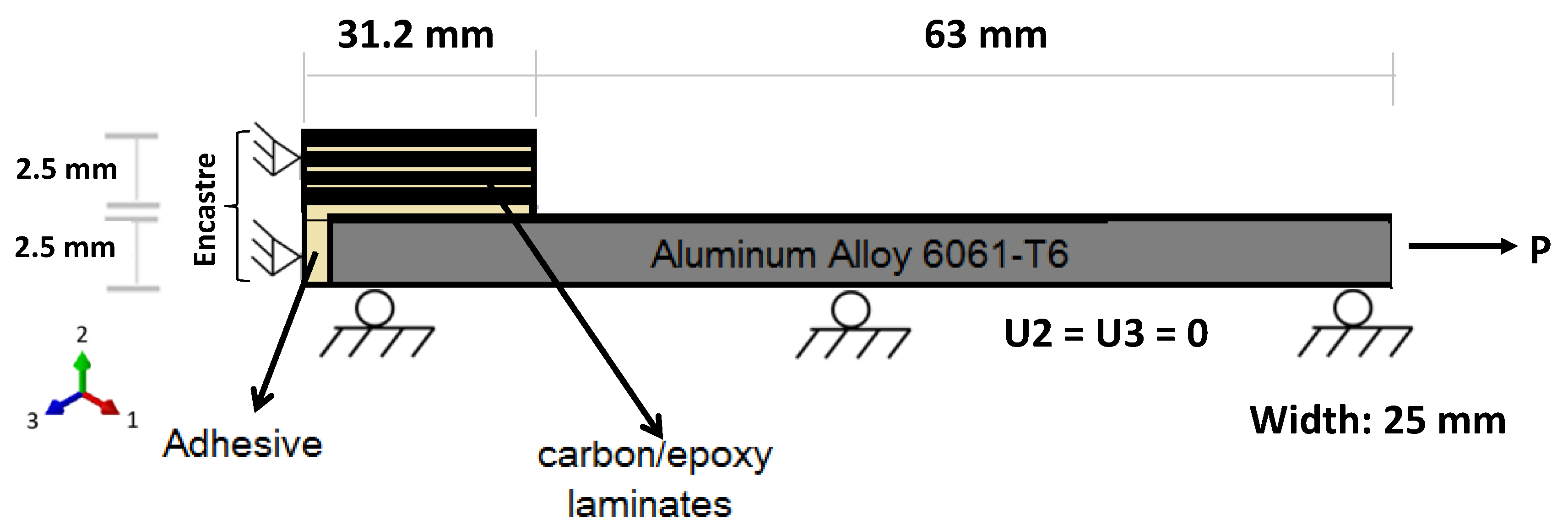
2.4. Specimen Configuration
3. Characterizing Method and Results
3.1. Tensile Test
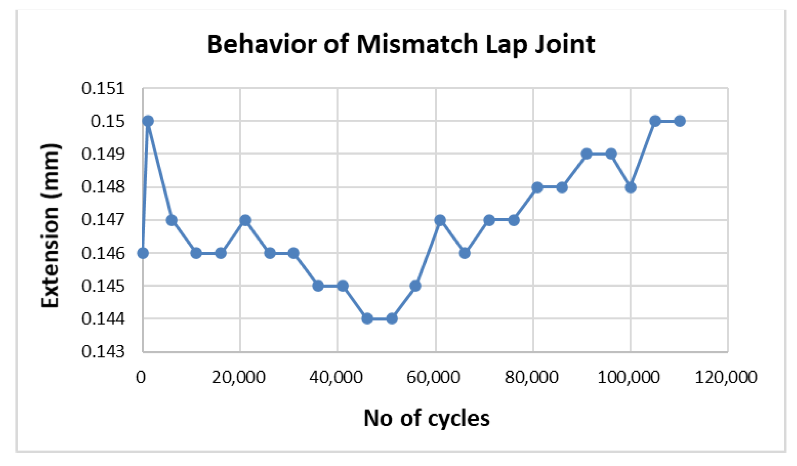
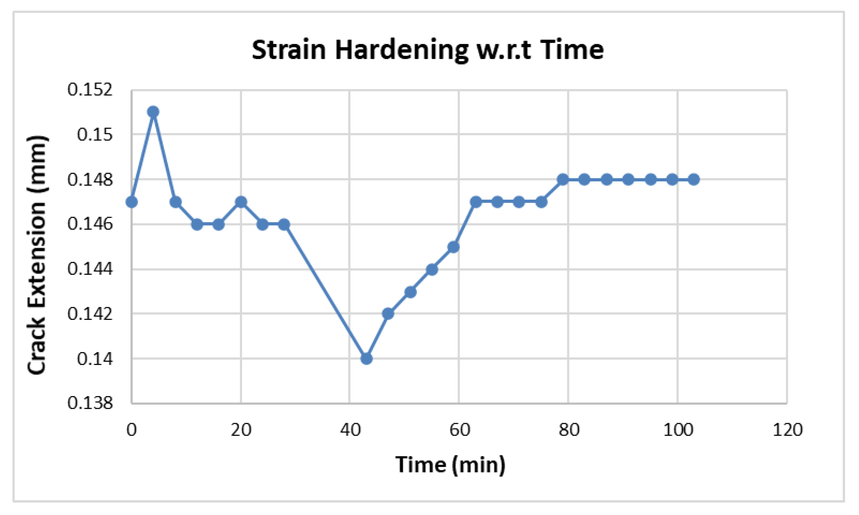
3.2. Fatigue Test
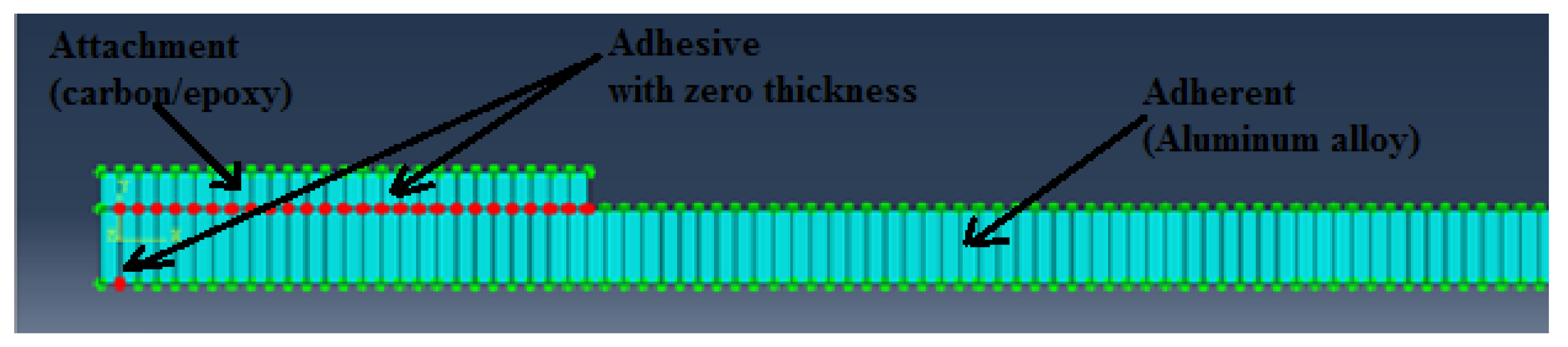
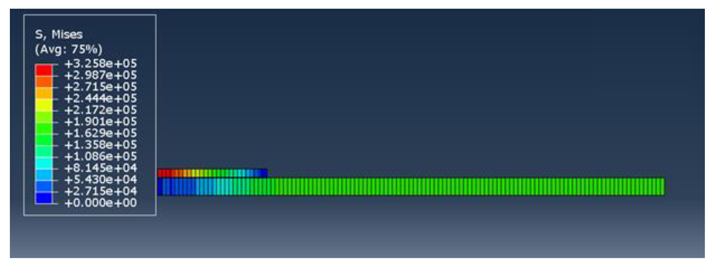
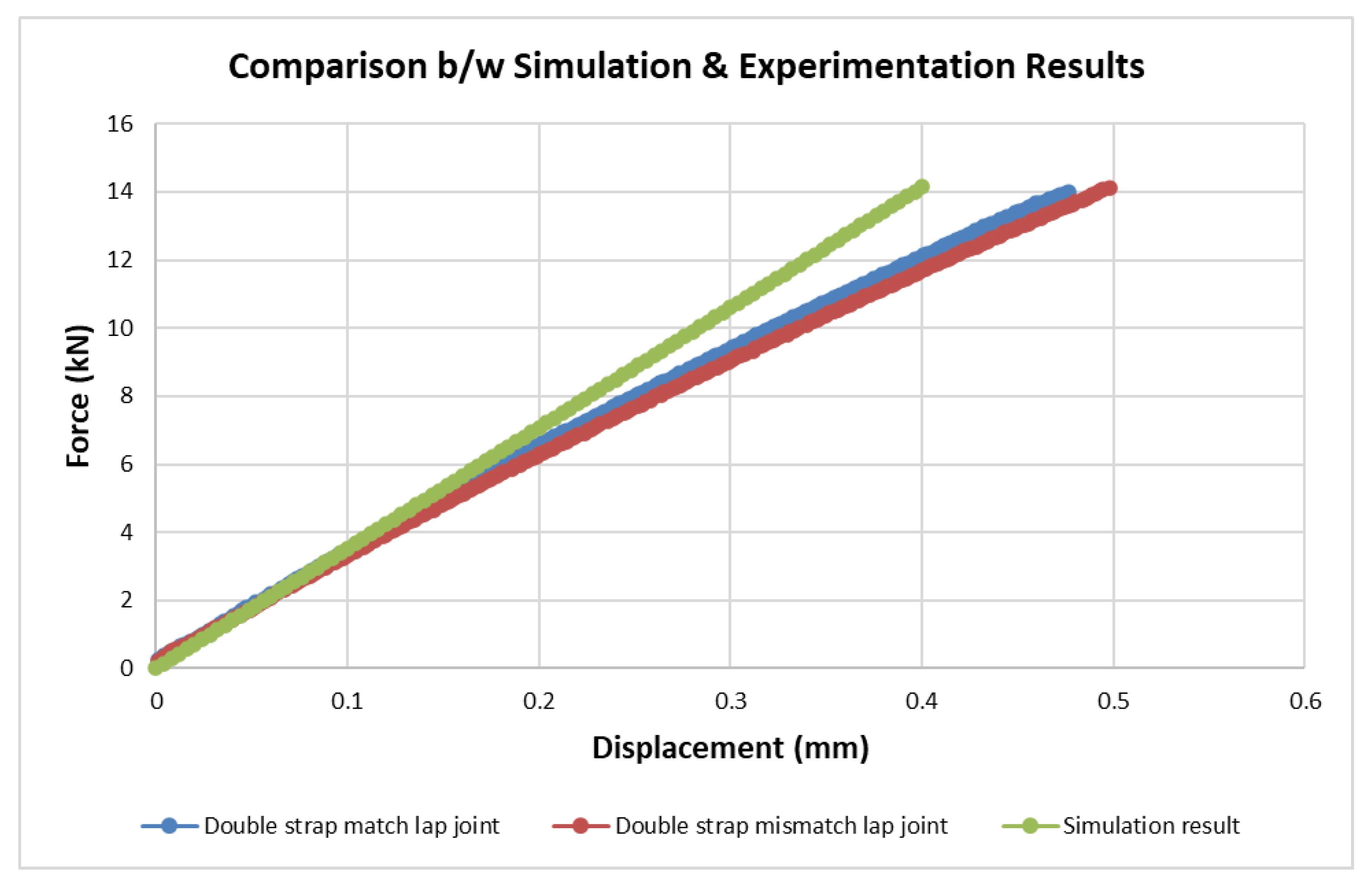
4. Finite Element Analysis
5. Conclusions
Author Contributions
Funding
Institutional Review Board Statement
Informed Consent Statement
Data Availability Statement
Acknowledgments
Conflicts of Interest
Nomenclature
| FMLs | Fiber metal laminates |
| CZM | Cohesive zone model |
| CARALL | Carbon-reinforced aluminum laminate |
| ASTM | American Society of Testing Materials |
| FEA | Finite element analysis |
References
- Lawcock, G.; Ye, L.; Mai, Y.-W.; Sun, C.-T. The Effect of Adhesive Bonding between Aluminum and Composite Prepreg on the Mechanical Properties of Carbon-Fiber-Reinforced Metal Laminates. Compos. Sci. Technol. 1997, 57, 35–45. [Google Scholar] [CrossRef]
- Pate, K.D. Chapter 25-Applications of Adhesives in Aerospace. In Adhesion Science and Engineering; Dillard, D.A., Pocius, A.V., Chaudhury, M., Eds.; Elsevier: Amsterdam, The Netherlands, 2002; pp. 1129–1192. ISBN 978-0-444-51140-9. [Google Scholar]
- Straznicky, P.; Laliberte, J.; Poon, C.; Fahr, A. Applications of Fiber-metal Laminates. Polym. Compos. 2004, 21, 558–567. [Google Scholar] [CrossRef]
- Chapter 7-Joint Design. In Adhesives Technology Handbook, 2nd ed.; Ebnesajjad, S. (Ed.) William Andrew Publishing: Norwich, NY, USA, 2009; pp. 159–181. ISBN 978-0-8155-1533-3. [Google Scholar]
- Pethrick, R.A. 5.15-Bond Inspection in Composite Structures. In Comprehensive Composite Materials; Kelly, A., Zweben, C., Eds.; Pergamon: Oxford, UK, 2000; pp. 359–392. ISBN 978-0-08-042993-9. [Google Scholar]
- Kanerva, M.; Saarela, O. The Peel Ply Surface Treatment for Adhesive Bonding of Composites: A Review. Int. J. Adhes. Adhes. 2013, 43, 60–69. [Google Scholar] [CrossRef]
- Arenas, J.M.; Alía, C.; Narbón, J.J.; Ocaña, R.; González, C. Considerations for the Industrial Application of Structural Adhesive Joints in the Aluminium–Composite Material Bonding. Compos. Part B Eng. 2013, 44, 417–423. [Google Scholar] [CrossRef]
- Arenas, M.A.; Conde, A.; de Damborenea, J.J. Effect of Acid Traces on Hydrothermal Sealing of Anodising Layers on 2024 Aluminium Alloy. Electrochim. Acta 2010, 55, 8704–8708. [Google Scholar] [CrossRef]
- Viejo, F.; Coy, A.E.; García-García, F.J.; Merino, M.C.; Liu, Z.; Skeldon, P.; Thompson, G.E. Enhanced Performance of the AA2050-T8 Aluminium Alloy Following Excimer Laser Surface Melting and Anodising Processes. Thin Solid Film. 2010, 518, 2722–2731. [Google Scholar] [CrossRef]
- Moutarlier, V.; Gigandet, M.; Pagetti, J.; Normand, B. Influence of Oxalic Acid Addition to Chromic Acid on the Anodising of Al 2024 Alloy. Surf. Coat. Technol.-SURF COAT TECH 2004, 182, 117–123. [Google Scholar] [CrossRef]
- Chuang, W.-Y.; Tsai, J.-L. Investigating the Performances of Stepwise Patched Double Lap Joint. Int. J. Adhes. Adhes. 2013, 42, 44–50. [Google Scholar] [CrossRef]
- Benyahia, F.; Albedah, A.; Bachir Bouiadjra, B. Analysis of the Adhesive Damage for Different Patch Shapes in Bonded Composite Repair of Aircraft Structures. Mater. Des. (1980–2015) 2014, 54, 18–24. [Google Scholar] [CrossRef]
- Meneghetti, G.; Quaresimin, M.; Ricotta, M. Damage Mechanisms in Composite Bonded Joints under Fatigue Loading. Compos. Part B Eng. 2012, 43, 210–220. [Google Scholar] [CrossRef]
- Quaresimin, M.; Ricotta, M. Fatigue Behaviour and Damage Evolution of Single Lap Bonded Joints in Composite Material. Compos. Sci. Technol. 2006, 66, 176–187. [Google Scholar] [CrossRef]
- Sandu, M.; Sandu, A.; Constantinescu, D.M.; Apostol, D.A. Single-Strap Adhesively Bonded Joints with Square or Tapered Adherends in Tensile Test Conditions. Int. J. Adhes. Adhes. 2013, 44, 105–114. [Google Scholar] [CrossRef]
- Akpinar, S. Effects of Laminate Carbon/Epoxy Composite Patches on the Strength of Double-Strap Adhesive Joints: Experimental and Numerical Analysis. Mater. Des. 2013, 51, 501–512. [Google Scholar] [CrossRef]
- Lee, H.K.; Pyo, S.H.; Kim, B.R. On Joint Strengths, Peel Stresses and Failure Modes in Adhesively Bonded Double-Strap and Supported Single-Lap GFRP Joints. Compos. Struct. 2009, 87, 44–54. [Google Scholar] [CrossRef]
- Fawzia, S.; Al-Mahaidi, R.; Zhao, X.-L. Experimental and Finite Element Analysis of a Double Strap Joint between Steel Plates and Normal Modulus CFRP. Compos. Struct. 2006, 75, 156–162. [Google Scholar] [CrossRef] [Green Version]
- Park, J.-H.; Choi, J.-H.; Kweon, J.-H. Evaluating the Strengths of Thick Aluminum-to-Aluminum Joints with Different Adhesive Lengths and Thicknesses. Compos. Struct. -COMPOS STRUCT 2010, 92, 2226–2235. [Google Scholar] [CrossRef]
- Nguyen, T.-C.; Bai, Y.; Zhao, X.; Al-Mahaidi, R. Mechanical Characterization of Steel/CFRP Double Strap Joints at Elevated Temperatures. Compos. Struct. 2011, 93, 1604–1612. [Google Scholar] [CrossRef]
- Nguyen, T.-C.; Bai, Y.; Zhao, X.-L.; Al-Mahaidi, R. Durability of Steel/CFRP Double Strap Joints Exposed to Sea Water, Cyclic Temperature and Humidity. Compos. Struct. 2012, 94, 1834–1845. [Google Scholar] [CrossRef]
- Bernasconi, A.; Jamil, A.; Moroni, F.; Pirondi, A. A Study on Fatigue Crack Propagation in Thick Composite Adhesively Bonded Joints. Int. J. Fatigue 2013, 50, 18–25. [Google Scholar] [CrossRef]
- Francine, R.; Desplanques, Y.; Degallaix, S. Fatigue of Glass/Epoxy Composite in Three-Point-Bending with Predominant Shearing. Int. J. Fatigue 2002, 24, 327–337. [Google Scholar] [CrossRef]
- Sinmazcelik, T.; Avcu, E.; Bora, M.; Coban, O. A Review: Fibre Metal Laminates, Background, Bonding Types and Applied Test Methods. Mater. Des. -MATER DESIGN 2011, 32, 3671–3685. [Google Scholar] [CrossRef]
- Al-Zubaidy, H.; Al-Mahaidi, R.; Zhao, X.-L. Finite Element Modelling of CFRP/Steel Double Strap Joints Subjected to Dynamic Tensile Loadings. Compos. Struct. 2013, 99, 48–61. [Google Scholar] [CrossRef]
- Campilho, R.D.S.G.; Banea, M.D.; Neto, J.A.B.P.; da Silva, L.F.M. Modelling Adhesive Joints with Cohesive Zone Models: Effect of the Cohesive Law Shape of the Adhesive Layer. Int. J. Adhes. Adhes. 2013, 44, 48–56. [Google Scholar] [CrossRef] [Green Version]
- He, X. A Review of Finite Element Analysis of Adhesively Bonded Joints. Int. J. Adhes. Adhes.-INT J ADHES ADHES 2011, 31, 248–264. [Google Scholar] [CrossRef]
- Cho, J.U.; Lee, S.K.; Cho, C.; Rodriguez Sanchez, F.S.; Blackman, B.R.K.; Kinloch, A.J. A Study on the Impact Behavior of Adhesively-Bonded Composite Materials. J. Mech. Sci. Technol. 2007, 21, 1671. [Google Scholar] [CrossRef]
- Cheuk, P.T.; Tong, L.; Wang, C.-H.; Baker, A.; Chalkley, P. Fatigue Crack Growth in Adhesively Bonded Composite-Metal Double-Lap Joints. Compos. Struct. 2002, 57, 109–115. [Google Scholar] [CrossRef]
- Trzepieciński, T.; Najm, S.M.; Sbayti, M.; Belhadjsalah, H.; Szpunar, M.; Lemu, H.G. New Advances and Future Possibilities in Forming Technology of Hybrid Metal–Polymer Composites Used in Aerospace Applications. J. Compos. Sci. 2021, 5, 217. [Google Scholar] [CrossRef]
- Vermeeren, C.A.J.R. An Historic Overview of the Development of Fibre Metal Laminates. Appl. Compos. Mater. 2003, 10, 189–205. [Google Scholar] [CrossRef]
- Bieniaś, J.; Jakubczak, P.; Surowska, B. 11-Properties and Characterization of Fiber Metal Laminates. In Hybrid Polymer Composite Materials; Thakur, V.K., Thakur, M.K., Pappu, A., Eds.; Woodhead Publishing: Sawston, UK, 2017; pp. 253–277. ISBN 978-0-08-100787-7. [Google Scholar]
- Li, H.; Hu, Y.; Fu, X.; Zheng, X.; Liu, H.; Tao, J. Effect of Adhesive Quantity on Failure Behavior and Mechanical Properties of Fiber Metal Laminates Based on the Aluminum–Lithium Alloy. Compos. Struct. 2016, 152, 687–692. [Google Scholar] [CrossRef]
- Kolanu, N.R.; Raju, G.; Ramji, M. A Unified Numerical Approach for the Simulation of Intra and Inter Laminar Damage Evolution in Stiffened CFRP Panels under Compression. Compos. Part B Eng. 2020, 190, 107931. [Google Scholar] [CrossRef]
- Rozylo, P. Failure Analysis of Thin-Walled Composite Structures Using Independent Advanced Damage Models. Compos. Struct. 2021, 262, 113598. [Google Scholar] [CrossRef]
- Tan, P. Numerical Simulation of the Ballistic Protection Performance of a Laminated Armor System with Pre-Existing Debonding/Delamination. Compos. Part B Eng. 2014, 59, 50–59. [Google Scholar] [CrossRef]
- Masud, M.; Al Kharusi, M.S.; Ali, M.U.; Mubashar, A.; Hussain, S.J.; Tariq, A.; Rehman, G.U.; Akhtar, M.H.; Javeed, S. Prediction of the Ultimate Strength of Notched and Unnotched IM7/977-3 Laminated Composites Using a Micromechanics Approach. Polymers 2021, 13, 3491. [Google Scholar] [CrossRef] [PubMed]
- Shah, S.Z.H.; Megat-Yusoff, P.S.M.; Karuppanan, S.; Choudhry, R.S.; Sajid, Z. Multiscale Damage Modelling of 3D Woven Composites under Static and Impact Loads. Compos. Part A Appl. Sci. Manuf. 2021, 151, 106659. [Google Scholar] [CrossRef]
- Kim, H.-K.; Park, E.-T.; Song, W.-J.; Kang, B.-S.; Kim, J. Experimental and Numerical Investigation of the High-Velocity Impact Resistance of Fiber Metal Laminates and Al 6061-T6 by Using Electromagnetic Launcher. J. Mech. Sci. Technol. 2019, 33, 1219–1229. [Google Scholar] [CrossRef]
- ASM International. ASM Handbook Volume 2: Properties and Selection: Nonferrous Alloys and Special-Purpose Materials; ASM International: Novelty, OH, USA, 1990; ISBN 978-0-87170-378-1. [Google Scholar]
- Lin, C.T.; Kao, P.W.; Yang, F.S. Fatigue Behaviour of Carbon Fibre-Reinforced Aluminium Laminates. Composites 1991, 22, 135–141. [Google Scholar] [CrossRef]
- Khan, F.; Qayyum, F.; Asghar, W.; Azeem, M.; Anjum, Z.; Nasir, A.; Shah, M. Effect of Various Surface Preparation Techniques on the Delamination Properties of Vacuum Infused Carbon Fiber Reinforced Aluminum Laminates (CARALL): Experimentation and Numerical Simulation. J. Mech. Sci. Technol. 2017, 31, 5265–5272. [Google Scholar] [CrossRef]
- Huntsman Advanced Materials. Advanced Materials; Araldite® LY 5052/Aradur® 5052* COLD CURING EPOXY SYSTEMS; Huntsman Advanced Materials: Woodloch, TX, USA, 2010. [Google Scholar]
- Wegman, R.F.; van Twisk, J. 2-Aluminum and Aluminum Alloys. In Surface Preparation Techniques for Adhesive Bonding, 2nd ed.; Wegman, R.F., van Twisk, J., Eds.; William Andrew Publishing: Norwich, NY, USA, 2013; pp. 9–37. ISBN 978-1-4557-3126-8. [Google Scholar]
- Critchlow, G.W.; Brewis, D.M. Review of Surface Pretreatments for Aluminium Alloys. Int. J. Adhes. Adhes. 1996, 16, 255–275. [Google Scholar] [CrossRef]
- Davis, M.; Bond, D. Principles and Practices of Adhesive Bonded Structural Joints and Repairs. Int. J. Adhes. Adhes. 1999, 19, 91–105. [Google Scholar] [CrossRef]
- ASTM International ASTM D3528-96(2016); Standard Test Method for Strength Properties of Double Lap Shear Adhesive Joints by Tension Loading. ASTM: West Conshohocken, PA, USA, 2016.
- Rotwitt, P.B. Fatigue Life Extension Using Composite Patch Repairs. Master’s Thesis, University of Oslo, Oslo, Norway, 2013. [Google Scholar]
- ASTM International ASTM D1002-10(2019); Standard Test Method for Apparent Shear Strength of Single-Lap-Joint Adhesively Bonded Metal Specimens by Tension Loading (Metal-to-Metal). ASTM: Novelty, OH, USA, 2019.
- ASTM International ASTM D3166-99(2020); Standard Test Method for Fatigue Properties of Adhesives in Shear by Tension Loading (Metal/Metal). ASTM: Novelty, OH, USA, 2020.
- Systèmes, D. Abaqus Standard and Abaqus Documentation for Version 6.14. Dassault Syst. Simulia Corp. 2014, 651, 2–6. [Google Scholar]


| Element | Si | Mg | Cu | Cr | Fe | Mn | Zn | Ti | Al |
| Weight % (max) | 0.8 | 1.2 | 0.4 | 0.35 | 0.7 | 0.15 | 0.25 | 0.15 | Bal |
| Specimen No. | Specimen Configuration | Code Assigned |
|---|---|---|
| 1 | Tensile test for double strap match lap joint | TT-M |
| 2 | Tensile test for double strap mismatch lap joint | TT-MM |
| 3 | Fatigue test for double strap match lap joint | FT-M |
| 4 | Fatigue test for double strap mismatch lap joint | FT-MM |
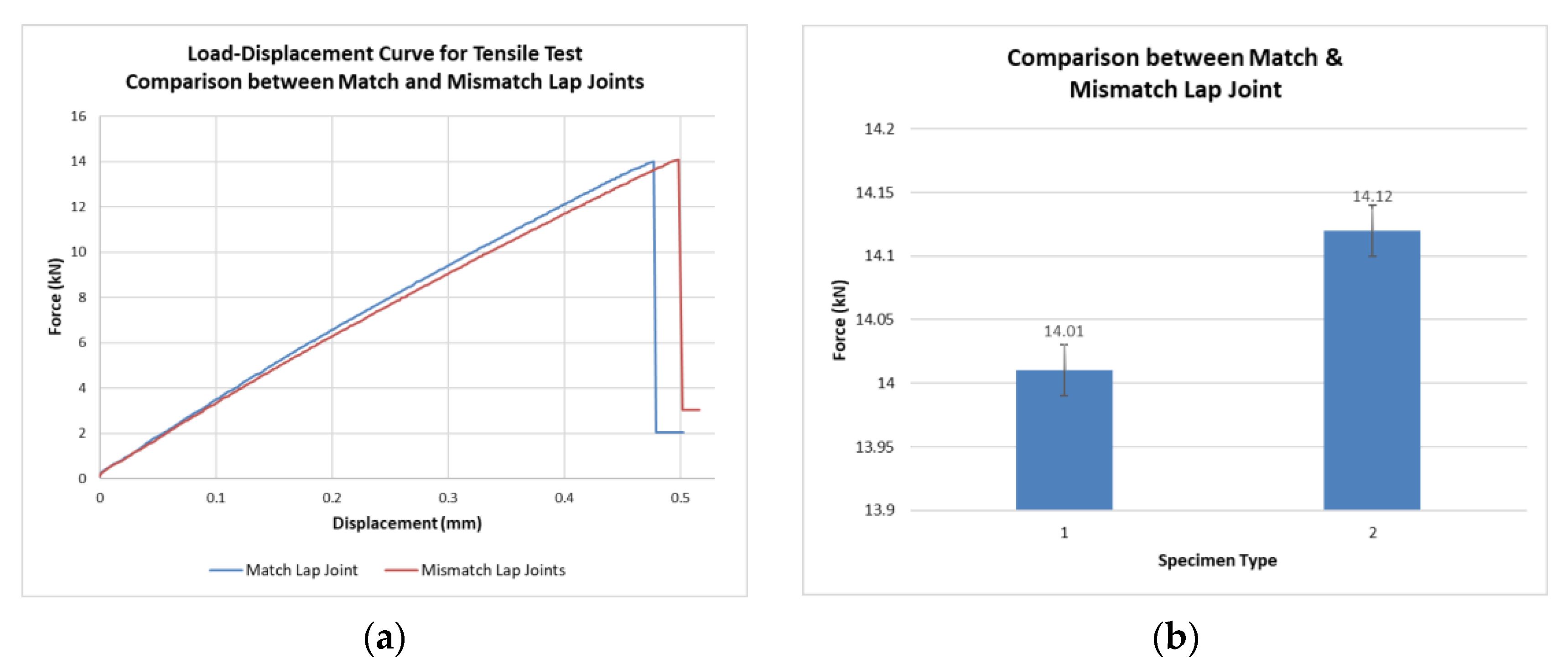
| Specimen Type | Failure Load kN | Failure Load Standard Deviation kN | Extension mm | Extension Standard Deviation mm | Fracture Energy (GIIC) J/m2 |
|---|---|---|---|---|---|
| 1 | 14.01 | 0.01 | 0.47 | 0.003 | 402 |
| 2 | 14.12 | 0.02 | 0.49 | 0.005 | 408.34 |
| Specimen Type | No. of Cycles | ||
|---|---|---|---|
| Sample 1 | Sample 2 | Sample 3 | |
| 3 | 25,737 | 76,135 | 76,243 |
| 4 | 110,000 | 110,340 | 110,169 |
| Materials | Density g/cm3 | Tensile Modulus GPa | Tensile Strength MPa | Poisson’s Ratio |
|---|---|---|---|---|
| Aluminum plate | 2.7 | 68.9 | 241 | 0.33 |
| Carbon fiber | 1.8 | 230 | 3450 | 0.35 |
| E/Knn GPa | G1/Kss GPa | G2/Ktt GPa |
|---|---|---|
| 3.44 | 1.27 | 1.27 |
| Simulation Result | Failure Load kN | Extension mm | Fracture Energy (GIIC) J/m2 |
|---|---|---|---|
| Double strap lap joint | 13.97 | 0.39 | 399.71 |
Publisher’s Note: MDPI stays neutral with regard to jurisdictional claims in published maps and institutional affiliations. |
© 2022 by the authors. Licensee MDPI, Basel, Switzerland. This article is an open access article distributed under the terms and conditions of the Creative Commons Attribution (CC BY) license (https://creativecommons.org/licenses/by/4.0/).
Share and Cite
Azeem, M.; Irfan, M.; Masud, M.; Rehman, G.U.; Ali, H.; Ali, M.U.; Zafar, A.; Muhammad Niazi, U.; Rahman, S.; Legutko, S.; et al. Experimental and Numerical Investigation of Effect of Static and Fatigue Loading on Behavior of Different Double Strap Adhesive Joint Configurations in Fiber Metal Laminates. Materials 2022, 15, 1840. https://doi.org/10.3390/ma15051840
Azeem M, Irfan M, Masud M, Rehman GU, Ali H, Ali MU, Zafar A, Muhammad Niazi U, Rahman S, Legutko S, et al. Experimental and Numerical Investigation of Effect of Static and Fatigue Loading on Behavior of Different Double Strap Adhesive Joint Configurations in Fiber Metal Laminates. Materials. 2022; 15(5):1840. https://doi.org/10.3390/ma15051840
Chicago/Turabian StyleAzeem, Muhammad, Muhammad Irfan, Manzar Masud, Gulfam Ul Rehman, Haider Ali, Muhammad Umair Ali, Amad Zafar, Usama Muhammad Niazi, Saifur Rahman, Stanislaw Legutko, and et al. 2022. "Experimental and Numerical Investigation of Effect of Static and Fatigue Loading on Behavior of Different Double Strap Adhesive Joint Configurations in Fiber Metal Laminates" Materials 15, no. 5: 1840. https://doi.org/10.3390/ma15051840