
Microstructure and Mechanical Properties of Dissimilar Friction Stir Welded Joint AA7020/AA5083 with Different Joining Parameters

 ,
,  , ,
, ,  and
and
Abstract
:1. Introduction
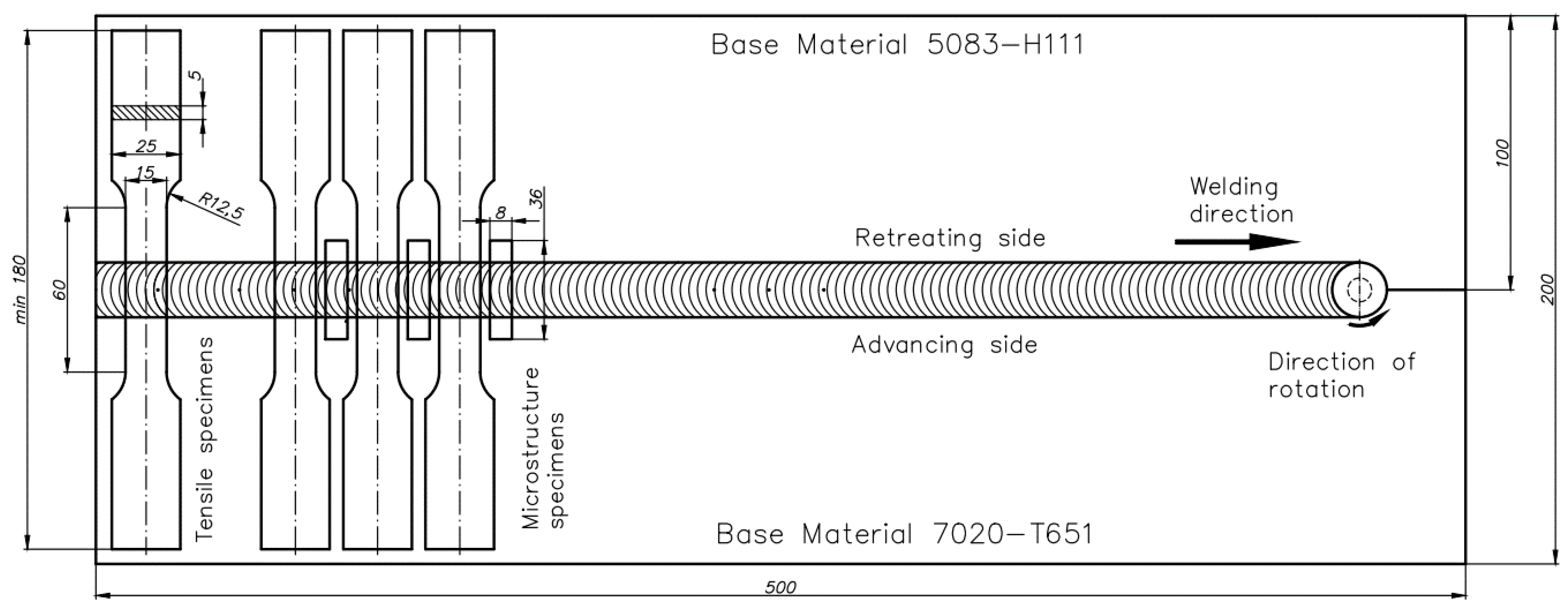
2. Material and Experimental Procedures
3. Results
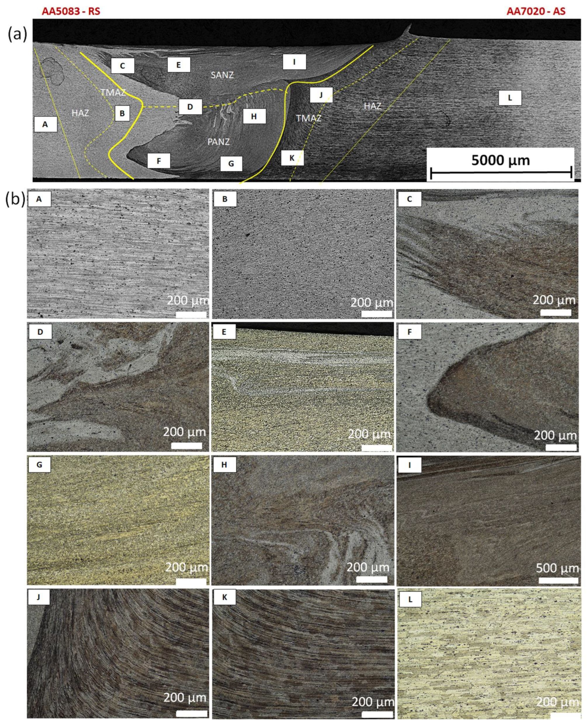
3.1. Macro and Microstructural Investigation
3.2. Microhardness Behavior
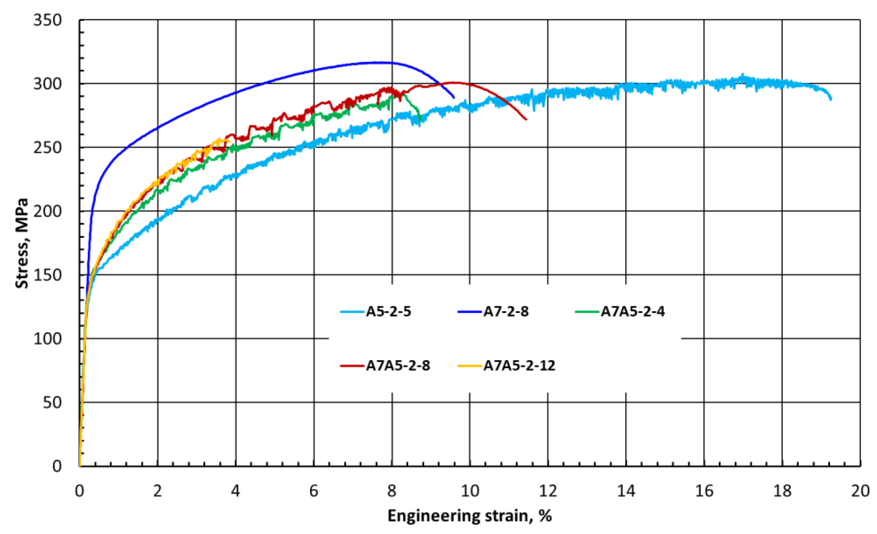
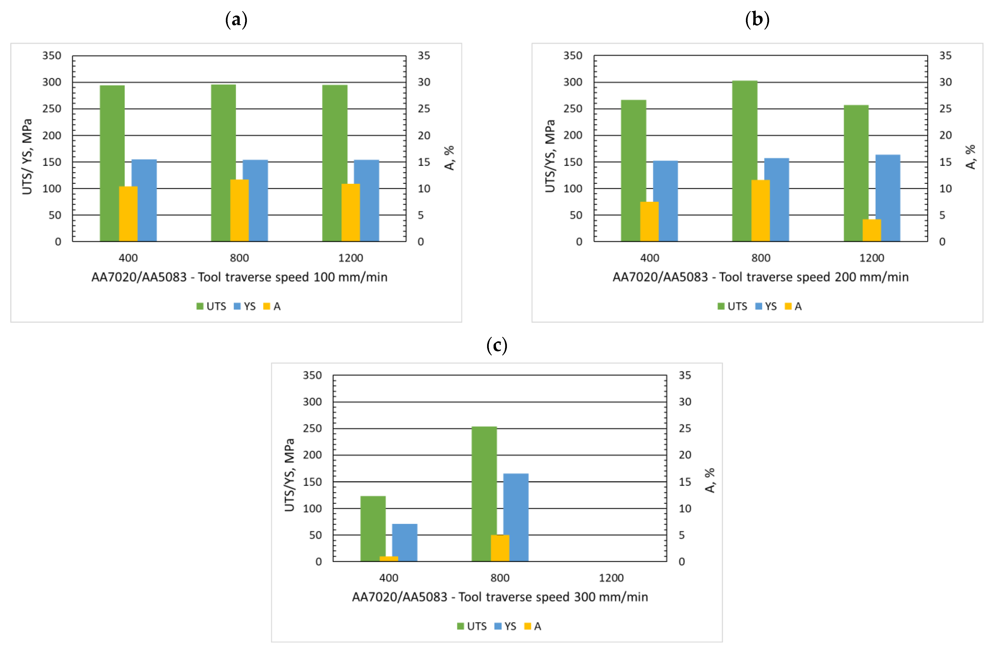
3.3. Tensile Properties
4. Discussion
4.1. Effect of Tool Rotational Speed
4.2. Efect of Tool Traverse Speed
5. Conclusions
- Incorrect selection of the welding speed and rotational speed of the tool leads to the formation of tunnel defects and wormhole defects, which were revealed despite the correct looking joint surfaces. The lack of bonding on the top surface of the joints was observed only in the case of the highest tool rotational speed (1200 rpm) and the highest welding speed (300 mm/min).
- The microscopic observations showed that complete mixing of the materials in the joint was not achieved for the tested alloys. Nevertheless, the strength properties were satisfactory and comparable to the weaker material in the joint: UTS = 303 MPa, YS = 157 MPa, and A = 11.6%.
- It was observed that there was no decrease in the hardness of the base materials in all heat affected-zones for both alloys and three profiles. Regardless of the position of the measuring line, a hardening process occurred in the welding region, and the Vickers micro-hardness for AA7020 alloy in the nugget zone reached values above 110 HV0.1.
- The best obtained 7020/5083 FSW joints showed up to 98% joint efficiency with the viewpoint of ultimate tensile strength weaker material in the joint (5083-H111) and exhibited almost 12% elongation, which exceeds the elongation of the base material (7020-T651).
- These studies show that the main parameters of the FSW process (tool rotational speed and tool traverse speed) cannot be considered separately, and their mutual influence on each other is difficult to describe with a simple relationship, especially concerning dissimilar joints. Motivated by the increase in productivity, the increase in the feed speed while maintaining a constant heat input ratio did not ensure obtaining the correct FSW joint.
Author Contributions
Funding
Institutional Review Board Statement
Informed Consent Statement
Data Availability Statement
Conflicts of Interest
References
- Aluminum Alloy Classification Systems—Knovel. Available online: https://app-1knovel-1com10000126r0084.han.wat.edu.pl/web/view/khtml/show.v/rcid:kpAMA00001/cid:kt00CZ0SN4/viewerType:khtml//root_slug:aerospace-materials-applications/url_slug:aluminum-alloy-classification?b-content-type=book%2Ctsection&b-q=aluminum%20al (accessed on 9 January 2022).
- Samal, P.; Vundavilli, P.R.; Meher, A.; Mahapatra, M.M. Recent progress in aluminum metal matrix composites: A review on processing, mechanical and wear properties. J. Manuf. Process. 2020, 59, 131–152. [Google Scholar] [CrossRef]
- Ahmed, M.M.Z.; Ataya, S.; El-Sayed Seleman, M.M.; Mahdy, A.M.A.; Alsaleh, N.A.; Ahmed, E. Metals Heat Input and Mechanical Properties Investigation of Friction Stir Welded AA5083/AA5754 and AA5083/AA7020. Metals 2021, 11, 68. [Google Scholar] [CrossRef]
- Mishra, R.S.; Ma, Z.Y. Friction stir welding and processing. Mater. Sci. Eng. R 2005, 50, 1–78. [Google Scholar] [CrossRef]
- Msomi, V.; Mbana, N. Mechanical Properties of Friction Stir Welded AA1050-H14 and AA5083-H111 Joint: Sampling Aspect. Metals 2020, 10, 214. [Google Scholar] [CrossRef] [Green Version]
- Haribalaji, V.; Boopathi, S.; Mohammed Asif, M. Optimization of Friction Stir Welding Process to Join Dissimilar AA2014 and AA7075 Aluminum Alloys. Mater. Today Proc. 2022, 50, 2227–2234. [Google Scholar] [CrossRef]
- Patel, V.; Li, W.; Wang, G.; Wang, F.; Vairis, A.; Niu, P. Friction Stir Welding of Dissimilar Aluminum Alloy Combinations: State-of-the-Art. Metals 2019, 9, 270. [Google Scholar] [CrossRef] [Green Version]
- Jenarthanan, M.P.; Varma, C.V.; Manohar, V. Impact of friction stir welding (FSW) process parameters on tensile strength during dissimilar welds of AA2014 and AA6061. Mater. Today Proc. 2018, 5, 14384–14391. [Google Scholar] [CrossRef]
- Dong, J.; Zhang, D.; Zhang, W.; Zhang, W.; Qiu, C. Microstructure Evolution during Dissimilar Friction Stir Welding of AA7003-T4 and AA6060-T4. Materials 2018, 11, 342. [Google Scholar] [CrossRef] [Green Version]
- Ahmed, M.M.Z.; Ataya, S.; El-Sayed Seleman, M.M.; Allam, T.; Alsaleh, N.A.; Ahmed, E. Grain Structure, Crystallographic Texture, and Hardening Behavior of Dissimilar Friction Stir Welded AA5083-O and AA5754-H14. Metals 2021, 11, 181. [Google Scholar] [CrossRef]
- Ilangovan, M.; Rajendra Boopathy, S.; Balasubramanian, V. Effect of tool pin profile on microstructure and tensile properties of friction stir welded dissimilar AA 6061–AA 5086 aluminium alloy joints. Def. Technol. 2015, 11, 174–184. [Google Scholar] [CrossRef] [Green Version]
- Kumar, P.S.; Chander, M.S. Effect of tool pin geometry on FSW dissimilar aluminum alloys—(AA5083 and AA6061). Mater. Today Proc. 2021, 39, 472–477. [Google Scholar] [CrossRef]
- Mastanaiah, P.; Sharma, A.; Reddy, G.M. Dissimilar Friction Stir Welds in AA2219-AA5083 Aluminium Alloys: Effect of Process Parameters on Material Inter-Mixing, Defect Formation, and Mechanical Properties. Trans. Indian Inst. Met. 2015, 69, 1397–1415. [Google Scholar] [CrossRef]
- Ahmed, M.M.Z.; Ataya, S.; El-Sayed Seleman, M.M.; Ammar, H.R.; Ahmed, E. Friction stir welding of similar and dissimilar AA7075 and AA5083. J. Mater. Process. Technol. 2017, 242, 77–91. [Google Scholar] [CrossRef]
- Rodriguez, R.; Jordon, J.; Allison, P.; Rushing, T.; Garcia, L. Microstructure and mechanical properties of dissimilar friction stir welding of 6061-to-7050 aluminum alloys. Mater. Des. 2015, 83, 60–65. [Google Scholar] [CrossRef]
- Shojaeefard, M.H.; Behnagh, R.A.; Akbari, M.; Givi, M.K.B.; Farhani, F. Modelling and Pareto optimization of mechanical properties of friction stir welded AA7075/AA5083 butt joints using neural network and particle swarm algorithm. Mater. Des. 2013, 44, 190–198. [Google Scholar] [CrossRef]
- Ramana, G.V.; Yelamasetti, B.; Vardhan, T.V. Effect of FSW process parameters and tool profile on mechanical properties of AA 5082 and AA 6061 welds. Mater. Today: Proc. 2021, 46, 826–830. [Google Scholar] [CrossRef]
- Bertrand, R.; Robe, H.; Texier, D.; Zedan, Y.; Feulvarch, E.; Bocher, P. Analysis of AA2XXX/AA7XXX friction stir welds. J. Mater. Process. Technol. 2019, 271, 312–324. [Google Scholar] [CrossRef] [Green Version]
- Mishra, R.S.; Mahoney, M.W. Friction Stir Welding and Processing; ASM International® Materials Park: Novelty, OH, USA, 2007. [Google Scholar]
- Threadgilll, P.L.; Leonard, A.J.; Shercliff, H.R.; Withers, P.J. Friction stir welding of aluminium alloys. Int. Mater. Rev. 2009, 54, 49–93. [Google Scholar] [CrossRef]
- Torzewski, J.; Grzelak, K.; Wachowski, M.; Kosturek, R. Microstructure and Low Cycle Fatigue Properties of AA5083 H111 Friction Stir Welded Joint. Materials 2020, 13, 2381. [Google Scholar] [CrossRef]
- Padhy, G.; Wu, C.S.; Gao, S. Friction stir based welding and processing technologies—Processes, parameters, microstructures and applications: A review. J. Mater. Sci. Technol. 2018, 34, 1–38. [Google Scholar] [CrossRef]
- Luijendijk, T. Welding of dissimilar aluminum alloys. J. Mater. Process Technol. 2000, 103, 29–35. [Google Scholar] [CrossRef]
- Seung-Ju, S.; Jungseok, K.; Woo, L.; Jae Yong, L.; Yohan, G.; Young, K. Influence of Friction Stir Welding on Mechanical Properties of Butt Joints of AZ61 Magnesium Alloy. Adv. Mater. Sci. Eng. 2017, 2017, 7381403. [Google Scholar]
- Dixit, V.; Mishra, R.; Lederich, R.J.; Talwar, R. Influence of process parameters on microstructural evolution and mechanical properties in friction stirred Al-2024 (T3) alloy. Sci. Technol. Weld. Join. 2009, 14, 346–355. [Google Scholar] [CrossRef]
- Arbegast, W. Hot Deformation of Aluminium Alloys III; TMS: Warrendale, PA, USA, 2003; pp. 313–327. [Google Scholar]
- Kasman, S.; Kahraman, F.; Emiralioglu, A. A Case Study for the Welding of Dissimilar EN AW 6082 and ENAW 5083 Aluminum Alloys by Friction Stir Welding. Metals 2016, 7, 6. [Google Scholar] [CrossRef] [Green Version]
- Kasman, Ş.; Yenier, Z. Analyzing dissimilar friction stir welding of AA5754/AA7075. Int. J. Adv. Manuf. Technol. 2014, 70, 145–156. [Google Scholar] [CrossRef]
- No, K.; Yoo, J.-T.; Yoon, J.-H.; Lee, H.-S. Effect of Process Parameters on Friction Stir Welds on AA2219-AA2195 Dissimilar Aluminum Alloys. Korean J. Mater. Res. 2017, 27, 331–338. [Google Scholar] [CrossRef]
- Kim, N.-K.; Kim, B.-C.; An, Y.-G.; Jung, B.-H.; Song, S.-W.; Kang, C.-Y. The effect of material arrangement on mechanical properties in Friction Stir Welded dissimilar A5052/A5J32 aluminum alloys. Met. Mater. Int. 2009, 15, 671–675. [Google Scholar] [CrossRef]
- Song, Y.; Yang, X.; Cui, L.; Hou, X.; Shen, Z.; Xu, Y. Defect features and mechanical properties of friction stir lap welded dissimilar AA2024–AA7075 aluminum alloy sheets. Mater. Des. 2014, 55, 9–18. [Google Scholar] [CrossRef]
- Ramachandran, K.K.; Murugan, N.; Shashi Kumar, S. Influence of tool traverse speed on the characteristics of dissimilar friction stir welded aluminium alloy, AA5052 and HSLA steel joints. Arch. Civ. Mech. Eng. 2015, 15, 822–830. [Google Scholar] [CrossRef]
- Koilraj, M.; Sundareswaran, V.; Vijayan, S.; Rao, S.K. Friction stir welding of dissimilar aluminum alloys AA2219 to AA5083—Optimization of process parameters using Taguchi technique. Mater. Des. 2012, 42, 1–7. [Google Scholar] [CrossRef]
- Karam, A.; Mahmoud, T.S.; Zakaria, H.M.; Khalifa, T.A. Friction Stir Welding of Dissimilar A319 and A413 Cast Aluminum Alloys. Arab. J. Sci. Eng. 2014, 39, 6363–6373. [Google Scholar] [CrossRef]
- Palanivel, R.; Laubscher, R.F.; Dinaharan, I.; Murugan, N. Developing a friction-stir welding window for joining the dissimilar aluminum alloys AA6351 and AA5083. Mater. Teh. 2017, 51, 5–9. [Google Scholar] [CrossRef]
- Guo, J.F.; Chen, H.C.; Sun, C.N.; Bi, G.; Sun, Z.; Wei, J. Friction stir welding of dissimilar materials between AA6061 and AA7075 Al alloys effects of process parameters. Mater. Des. 2013, 56, 185–192. [Google Scholar] [CrossRef]


| Alloy | Al | Mg | Mn | Si | Fe | Cr | Zn | Ti | Cu |
|---|---|---|---|---|---|---|---|---|---|
| AA5083 | Bal. | 4.34 | 0.63 | 0.076 | 0.13 | 0.064 | 0.035 | 0.055 | 0.032 |
| AA7020 | Bal. | 1.30 | 0.24 | 0.16 | 0.32 | 0.14 | 4.7 | 0.034 | 0.05 |
| Alloy | Tensile Strength (MPa) | 0.2% Yield Strength (MPa) | Elongation (%) | Microhardness Hv0.1 |
|---|---|---|---|---|
| AA5083-H111 | 310 | 165 | 20.2 | 82 |
| AA7020-T651 | 390 | 300 | 8.6 | 107 |
| Processing Parameter | Tool Rotational Speed, ω (rpm) | |||
|---|---|---|---|---|
| 400 | 800 | 1200 | ||
| Tool traverse speed, v (mm/min) | 100 | A7A5-1-4 | A7A5-1-8 | A7A5-1-12 |
| 200 | A7A5-2-4 | A7A5-2-8 | A7A5-2-12 | |
| 300 | A7A5-3-4 | A7A5-3-8 | A7A5-3-12 | |
| Sample Designation | Surface Morphology | FSW Joints Macrostructure |
|---|---|---|
| A7A5–1–4 | 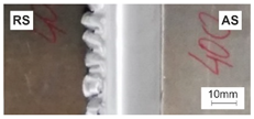 |  |
| A7A5–1–8 | 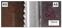 | 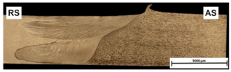 |
| A7A5–1–12 | 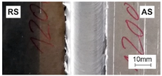 |  |
| A7A5–2–4 |  | 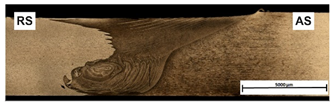 |
| A7A5–2–8 | 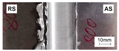 |  |
| A7A5–2–12 | 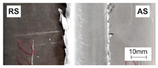 | 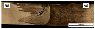 |
| A7A5–3–4 | 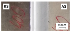 | 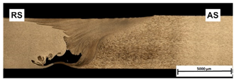 |
| A7A5–3–8 | 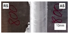 | 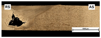 |
| Sample Designation | Tensile Strength (MPa) | 0.2% Yield Strength (MPa) | Elongation (%) | Weld Efficiency (%) |
|---|---|---|---|---|
| A7A5-1-4 | 294 (±3.2) | 155 (±1) | 10.4 (±1.7) | 95 |
| A7A5-1-8 | 296 (±6.1) | 154 (±3.5) | 11.7 (±0.8) | 95 |
| A7A5-1-12 | 295 (±0.1) | 154 (±0.6) | 10.9 (±0.2) | 95 |
| A7A5-2-4 | 267 (±25) | 152 (±1.7) | 7.5 (±4.5) | 86 |
| A7A5-2-8 | 303 (±1.8) | 157 (±1.1) | 11.6 (±0.2) | 98 |
| A7A5-2-12 | 256.6 (±7.8) | 164 (±0.5) | 4.2 (±0.3) | 83 |
| A7A5-3-4 | 123 (±24) | 71 (±26.2) | 0.95 (±0.05) | 40 |
| A7A5-3-8 | 254 (±47.7) | 165 (±0.7) | 5 (±3.6) | 82 |
| Sample Designation v-ω | A5A7-1-4 | A5A7-1-8 | A5A7-1-12 | A5A7-2-4 | A5A7-2-8 | A5A7-2-12 | A5A7-3-4 | A5A7-3-8 | A5A7-3-12 |
|---|---|---|---|---|---|---|---|---|---|
| Heat Input Ratio | 4 | 8 | 12 | 2 | 4 | 6 | 1.3 | 2.6 | 4 |
| Heat Input Index | 0.16 | 0.64 | 1.44 | 0.08 | 0.32 | 0.72 | 0.053 | 0.213 | 0.48 |
Publisher’s Note: MDPI stays neutral with regard to jurisdictional claims in published maps and institutional affiliations. |
© 2022 by the authors. Licensee MDPI, Basel, Switzerland. This article is an open access article distributed under the terms and conditions of the Creative Commons Attribution (CC BY) license (https://creativecommons.org/licenses/by/4.0/).
Share and Cite
Torzewski, J.; Łazińska, M.; Grzelak, K.; Szachogłuchowicz, I.; Mierzyński, J. Microstructure and Mechanical Properties of Dissimilar Friction Stir Welded Joint AA7020/AA5083 with Different Joining Parameters. Materials 2022, 15, 1910. https://doi.org/10.3390/ma15051910
Torzewski J, Łazińska M, Grzelak K, Szachogłuchowicz I, Mierzyński J. Microstructure and Mechanical Properties of Dissimilar Friction Stir Welded Joint AA7020/AA5083 with Different Joining Parameters. Materials. 2022; 15(5):1910. https://doi.org/10.3390/ma15051910
Chicago/Turabian StyleTorzewski, Janusz, Magdalena Łazińska, Krzysztof Grzelak, Ireneusz Szachogłuchowicz, and Janusz Mierzyński. 2022. "Microstructure and Mechanical Properties of Dissimilar Friction Stir Welded Joint AA7020/AA5083 with Different Joining Parameters" Materials 15, no. 5: 1910. https://doi.org/10.3390/ma15051910
APA StyleTorzewski, J., Łazińska, M., Grzelak, K., Szachogłuchowicz, I., & Mierzyński, J. (2022). Microstructure and Mechanical Properties of Dissimilar Friction Stir Welded Joint AA7020/AA5083 with Different Joining Parameters. Materials, 15(5), 1910. https://doi.org/10.3390/ma15051910