
Boron Oxide Enhancing Stability of MoS2 Anode Materials for Lithium-Ion Batteries


Abstract
:
1. Introduction
2. Materials and Methods
2.1. Chemical Materials
2.2. Exfoliation of MoS2 NSs
2.3. Preparation of Boron Oxide Decorated MoS2 NS
2.4. Material Characterization
2.5. Electrochemical Measurements
3. Results and Discussion
4. Conclusions
Author Contributions
Funding
Institutional Review Board Statement
Informed Consent Statement
Data Availability Statement
Conflicts of Interest
References
- Yang, J.; Shin, H.S. Recent advances in layered transition metal dichalcogenides for hydrogen evolution reaction. J. Mater. Chem. A 2014, 2, 5979–5985. [Google Scholar] [CrossRef]
- Kwon, K.C.; Kim, C.; Le, Q.V.; Gim, S.; Jeon, J.-M.; Ham, J.Y.; Lee, J.-L.; Jang, H.W.; Kim, S.Y. Synthesis of Atomically Thin Transition Metal Disulfides for Charge Transport Layers in Optoelectronic Devices. ACS Nano 2015, 9, 4146–4155. [Google Scholar] [CrossRef] [PubMed]
- Yang, T.; Song, T.T.; Callsen, M.; Zhou, J.; Chai, J.W.; Feng, Y.P.; Wang, S.J.; Yang, M. Atomically Thin 2D Transition Metal Oxides: Structural Reconstruction, Interaction with Substrates, and Potential Applications. Adv. Mater. Interfaces 2019, 6, 1801160. [Google Scholar] [CrossRef] [Green Version]
- Tan, C.; Zhang, H. Two-dimensional transition metal dichalcogenide nanosheet-based composites. Chem. Soc. Rev. 2015, 44, 2713–2731. [Google Scholar] [CrossRef] [PubMed]
- Chhowalla, M.; Shin, H.S.; Eda, G.; Li, L.J.; Loh, K.P.; Zhang, H. The chemistry of two-dimensional layered transition metal dichalcogenide nanosheets. Nat. Chem. 2013, 5, 263–275. [Google Scholar] [CrossRef]
- Castellanos-Gomez, A.; Poot, M.; Steele, G.A.; Van der Zant, H.S.; Agraït, N.; Rubio-Bollinger, G. Mechanical properties of freely suspended semiconducting graphene-like layers based on MoS2. Nanoscale. Res. Lett. 2012, 7, 233. [Google Scholar] [CrossRef] [PubMed] [Green Version]
- Radisavljevic, B.; Radenovic, A.; Brivio, J.; Giacometti, V.; Kis, A. Single-layer MoS2 transistors. Nat. Nanotechnol. 2011, 6, 147–150. [Google Scholar] [CrossRef]
- Xu, M.; Liang, T.; Shi, M.; Chen, H. Graphene-Like Two-Dimensional Materials. Chem. Rev. 2013, 113, 3766–3798. [Google Scholar] [CrossRef]
- Kim, C.; Nguyen, T.P.; Le, Q.V.; Jeon, J.M.; Jang, H.W.; Kim, S.Y. Performances of Liquid-Exfoliated Transition Metal Dichalcogenides as Hole Injection Layers in Organic Light-Emitting Diodes. Adv. Funct. Mater. 2015, 25, 4512–4519. [Google Scholar] [CrossRef]
- Nguyen, V.H.; Nguyen, T.P.; Le, T.H.; Vo, D.V.N.; Nguyen, D.L.T.; Trinh, Q.T.; Kim, I.T.; Le, Q.V. Recent advances in two-dimensional transition metal dichalcogenides as photoelectrocatalyst for hydrogen evolution reaction. J. Chem. Technol. Biotechnol. 2020, 95, 2597–2607. [Google Scholar] [CrossRef]
- Stephenson, T.; Li, Z.; Olsen, B.; Mitlin, D. Lithium ion battery applications of molybdenum disulfide (MoS2) nanocomposites. Energy Environ. Sci. 2014, 7, 209–231. [Google Scholar] [CrossRef]
- Shu, H.; Li, F.; Hu, C.; Liang, P.; Cao, D.; Chen, X. The capacity fading mechanism and improvement of cycling stability in MoS2-based anode materials for lithium-ion batteries. Nanoscale 2016, 8, 2918–2926. [Google Scholar] [CrossRef] [PubMed]
- Wang, Z.; von dem Bussche, A.; Qiu, Y.; Valentin, T.M.; Gion, K.; Kane, A.B.; Hurt, R.H. Chemical Dissolution Pathways of MoS2 Nanosheets in Biological and Environmental Media. Environ. Sci. Technol. 2016, 50, 7208–7217. [Google Scholar] [CrossRef] [PubMed] [Green Version]
- Xiao, J.; Wang, X.J.; Yang, X.Q.; Xun, S.D.; Liu, G.; Koech, P.K.; Liu, J.; Lemmon, J.P. Electrochemically Induced High Capacity Displacement Reaction of PEO/MoS2/Graphene Nanocomposites with Lithium. Adv. Funct. Mater. 2011, 21, 2840–2846. [Google Scholar] [CrossRef]
- Xiang, T.; Fang, Q.; Xie, H.; Wu, C.; Wang, C.; Zhou, Y.; Liu, D.; Chen, S.; Khalil, A.; Tao, S.; et al. Vertical 1T-MoS2 nanosheets with expanded interlayer spacing edged on a graphene frame for high rate lithium-ion batteries. Nanoscale 2017, 9, 6975–6983. [Google Scholar] [CrossRef]
- Nguyen, T.P.; Kim, I.T. Ag Nanoparticle-Decorated MoS2 Nanosheets for Enhancing Electrochemical Performance in Lithium Storage. Nanomaterials 2021, 11, 626. [Google Scholar] [CrossRef]
- Zhu, X.; Yang, C.; Xiao, F.; Wang, J.; Su, X. Synthesis of nano-TiO2-decorated MoS2 nanosheets for lithium ion batteries. J. Chem. 2015, 39, 683–688. [Google Scholar] [CrossRef]
- Lu, L.; Min, F.; Luo, Z.; Wang, S.; Teng, F.; Li, G.; Feng, C. Synthesis and electrochemical properties of tin-doped MoS2 (Sn/MoS2) composites for lithium ion battery applications. J. Nanopart. Res. 2016, 18, 357. [Google Scholar] [CrossRef]
- Chen, Y.; Lu, J.; Wen, S.; Lu, L.; Xue, J. Synthesis of SnO2/MoS2 composites with different component ratios and their applications as lithium ion battery anodes. J. Mater. Chem. A 2014, 2, 17857–17866. [Google Scholar] [CrossRef]
- Li, Z.; Sun, P.; Zhan, X.; Zheng, Q.; Feng, T.; Braun, P.V.; Qi, S. Metallic 1T phase MoS2/MnO composites with improved cyclability for lithium-ion battery anodes. J. Alloys Compd. 2019, 796, 25–32. [Google Scholar] [CrossRef]
- Kong, D.; He, H.; Song, Q.; Wang, B.; Lv, W.; Yang, Q.-H.; Zhi, L. Rational design of MoS2@graphene nanocables: Towards high performance electrode materials for lithium ion batteries. Energy Environ. Sci. 2014, 7, 3320–3325. [Google Scholar] [CrossRef]
- Yoo, H.; Tiwari, A.P.; Lee, J.; Kim, D.; Park, J.H.; Lee, H. Cylindrical nanostructured MoS2 directly grown on CNT composites for lithium-ion batteries. Nanoscale 2015, 7, 3404–3409. [Google Scholar] [CrossRef] [PubMed]
- Ren, J.; Ren, R.-P.; Lv, Y.-K. A flexible 3D graphene@CNT@MoS2 hybrid foam anode for high-performance lithium-ion battery. Chem. Eng. J. 2018, 353, 419–424. [Google Scholar] [CrossRef]
- Qu, B.; Sun, Y.; Liu, L.; Li, C.; Yu, C.; Zhang, X.; Chen, Y. Ultrasmall Fe2O3 nanoparticles/MoS2 nanosheets composite as high-performance anode material for lithium ion batteries. Sci. Rep. 2017, 7, 42772. [Google Scholar] [CrossRef]
- Zhao, S.; Zha, Z.; Liu, X.; Tian, H.; Wu, Z.; Li, W.; Sun, L.-B.; Liu, B.; Chen, Z. Core–Sheath Structured MoO3@MoS2 Composite for High-Performance Lithium-Ion Battery Anodes. Energy Fuels 2020, 34, 11498–11507. [Google Scholar] [CrossRef]
- Yoon, M.; Dong, Y.; Hwang, J.; Sung, J.; Cha, H.; Ahn, K.; Huang, Y.; Kang, S.J.; Li, J.; Cho, J. Reactive boride infusion stabilizes Ni-rich cathodes for lithium-ion batteries. Nat. Energy 2021, 6, 362–371. [Google Scholar] [CrossRef]
- Li, J.; Liu, Z.; Wang, Y.; Wang, R. Investigation of facial B2O3 surface modification effect on the cycling stability and high-rate capacity of LiNi1/3Co1/3Mn1/3O2 cathode. J. Alloys Compd. 2020, 834, 155150. [Google Scholar] [CrossRef]
- Hayashi, A.; Nakai, M.; Tatsumisago, M.; Minami, T.; Katada, M. Structural Studies in Lithium Insertion into SnO-B2O3 Glasses and Their Applications for All-Solid-State Batteries. J. Electrochem. Soc. 2003, 150, A582. [Google Scholar] [CrossRef]
- Vijayakumar, E.; Govinda raj, M.; Neppolian, B.; Kumar Lakhera, S.; John Bosco, A. Hierarchical layered nanostructure of MoS2/boron doped reduced graphene oxide composites under visible light irradiation for effective antibiotic degradation and hexavalent chromium reduction. Mater. Lett. 2021, 296, 129891. [Google Scholar] [CrossRef]
- Riyanto; Sahroni, I.; Bindumadhavan, K.; Chang, P.Y.; Doong, R.A. Boron Doped Graphene Quantum Structure and MoS2 Nanohybrid as Anode Materials for Highly Reversible Lithium Storage. Front. Chem. 2019, 7, 116. [Google Scholar] [CrossRef]
- Balcı, S.; Sezgi, N.A.; Eren, E. Boron Oxide Production Kinetics Using Boric Acid as Raw Material. Ind. Eng. Chem. Res. 2012, 51, 11091–11096. [Google Scholar] [CrossRef]
- Huber, C.; Jahromy, S.S.; Jordan, C.; Schreiner, M.; Harasek, M.; Werner, A.; Winter, F. Boric Acid: A High Potential Candidate for Thermochemical Energy Storage. Energies 2019, 12, 1086. [Google Scholar] [CrossRef] [Green Version]
- Nguyen, T.P.; Kim, I.T. Self-Assembled Few-Layered MoS2 on SnO2 Anode for Enhancing Lithium-Ion Storage. Nanomaterials 2020, 10, 2558. [Google Scholar] [CrossRef] [PubMed]
- Bai, S.; Wang, L.; Chen, X.; Du, J.; Xiong, Y. Chemically exfoliated metallic MoS2 nanosheets: A promising supporting co-catalyst for enhancing the photocatalytic performance of TiO2 nanocrystals. Nano Res. 2015, 8, 175–183. [Google Scholar] [CrossRef]
- Nguyen, T.P.; Sohn, W.; Oh, J.H.; Jang, H.W.; Kim, S.Y. Size-Dependent Properties of Two-Dimensional MoS2 and WS2. J. Phys. Chem. C 2016, 120, 10078–10085. [Google Scholar] [CrossRef]
- Voiry, D.; Yamaguchi, H.; Li, J.; Silva, R.; Alves, D.C.B.; Fujita, T.; Chen, M.; Asefa, T.; Shenoy, V.B.; Eda, G.; et al. Enhanced catalytic activity in strained chemically exfoliated WS2 nanosheets for hydrogen evolution. Nat. Mater. 2013, 12, 850–855. [Google Scholar] [CrossRef] [PubMed]
- George, C.; Morris, A.J.; Modarres, M.H.; De Volder, M. Structural Evolution of Electrochemically Lithiated MoS2 Nanosheets and the Role of Carbon Additive in Li-Ion Batteries. Chem. Mater. 2016, 28, 7304–7310. [Google Scholar] [CrossRef] [Green Version]
- Liu, R.; Li, D.; Tian, D.; Xia, G.; Wang, C.; Xiao, N.; Li, N.; Mack, N.H.; Li, Q.; Wu, G. Promotional role of B2O3 in enhancing hollow SnO2 anode performance for Li-ion batteries. J. Power Sources 2014, 251, 279–286. [Google Scholar] [CrossRef]
- Pritchard, H.O. The Determination of Electron Affinities. Chem. Rev. 1953, 52, 529–563. [Google Scholar] [CrossRef]
- Pender, J.P.; Jha, G.; Youn, D.H.; Ziegler, J.M.; Andoni, I.; Choi, E.J.; Heller, A.; Dunn, B.S.; Weiss, P.S.; Penner, R.M.; et al. Electrode Degradation in Lithium-Ion Batteries. ACS Nano 2020, 14, 1243–1295. [Google Scholar] [CrossRef] [Green Version]
- Choi, S.H.; Lee, S.J.; Kim, H.J.; Park, S.B.; Choi, J.W. Li2O–B2O3–GeO2 glass as a high performance anode material for rechargeable lithium-ion batteries. J. Mater. Chem. A 2018, 6, 6860–6866. [Google Scholar] [CrossRef]
- Li, G.; Huang, Q.; He, X.; Gao, Y.; Wang, D.; Kim, S.H.; Wang, D. Self-Formed Hybrid Interphase Layer on Lithium Metal for High-Performance Lithium–Sulfur Batteries. ACS Nano 2018, 12, 1500–1507. [Google Scholar] [CrossRef] [PubMed]
- Zhang, C.; Lin, Y.; Liu, J. Sulfur double locked by a macro-structural cathode and a solid polymer electrolyte for lithium–sulfur batteries. J. Mater. Chem. A 2015, 3, 10760–10766. [Google Scholar] [CrossRef]
- Huang, L.; Xu, L.; Yang, Y.; Yu, H.; Tao, H.; Li, D.; Dong, X. Superhydrophilic MoS2–Ni3S2 nanoflake heterostructures grown on 3D Ni foam as an efficient electrocatalyst for overall water splitting. J. Mater. Sci. Mater. Electron 2020, 31, 6607–6617. [Google Scholar] [CrossRef]
- Fominski, V.; Demin, M.; Nevolin, V.; Fominski, D.; Romanov, R.; Gritskevich, M.; Smirnov, N. Reactive Pulsed Laser Deposition of Clustered-Type MoSx (x ~ 2, 3, and 4) Films and Their Solid Lubricant Properties at Low Temperature. Nanomaterials 2020, 10, 653. [Google Scholar] [CrossRef] [Green Version]
- Hussain, S.; Singh, J.; Vikraman, D.; Singh, A.K.; Iqbal, M.Z.; Khan, M.F.; Kumar, P.; Choi, D.-C.; Song, W.; An, K.-S.; et al. Large-area, continuous and high electrical performances of bilayer to few layers MoS2 fabricated by RF sputtering via post-deposition annealing method. Sci. Rep. 2016, 6, 30791. [Google Scholar] [CrossRef] [Green Version]
- David, L.; Bhandavat, R.; Barrera, U.; Singh, G. Polymer-Derived Ceramic Functionalized MoS2 Composite Paper as a Stable Lithium-Ion Battery Electrode. Sci. Rep. 2015, 5, 9792. [Google Scholar] [CrossRef] [Green Version]
- Hu, S.; Chen, W.; Zhou, J.; Yin, F.; Uchaker, E.; Zhang, Q.; Cao, G. Preparation of carbon coated MoS2 flower-like nanostructure with self-assembled nanosheets as high-performance lithium-ion battery anodes. J. Mater. Chem. A 2014, 2, 7862–7872. [Google Scholar] [CrossRef]
- Rana, M.; Boaretto, N.; Mikhalchan, A.; Vila Santos, M.; Marcilla, R.; Vilatela, J.J. Composite Fabrics of Conformal MoS2 Grown on CNT Fibers: Tough Battery Anodes without Metals or Binders. ACS Appl. Energy Mater. 2021, 4, 5668–5676. [Google Scholar] [CrossRef]


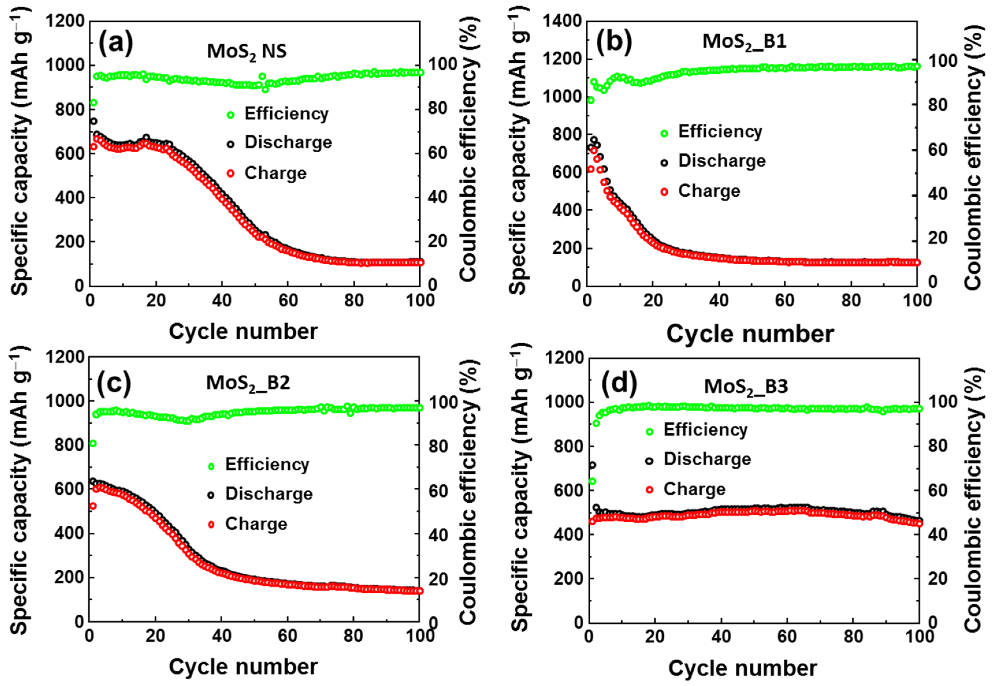
| Anode | Initial Capacity (mAh g−1) | Current Rate (A∙g−1) | Capacity after 100 Cycles (mAh∙g−1) |
|---|---|---|---|
| Bare MoS2 | 747.1 | 0.1 | 109 |
| MoS2_B1 | 717.7 | 0.1 | 125 |
| MoS2_B2 | 638.1 | 0.1 | 140 |
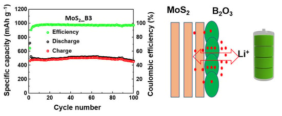
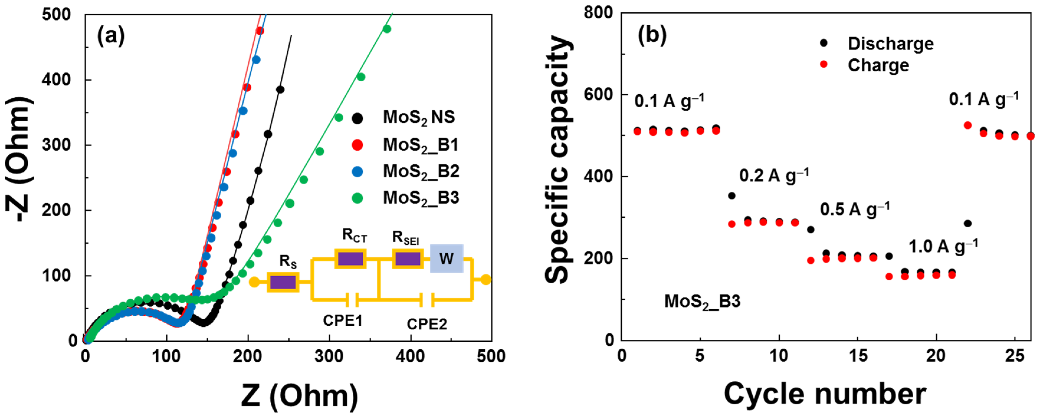
| MoS2_B3 | 717.2 | 0.1 | 451 |
| Anode Material | Current Density (A∙g−1) | Initial Discharge Capacity (mAh∙g−1) | Cycle Number | Specific Capacity (mAh∙g−1) | References |
|---|---|---|---|---|---|
| Ag decorated MoS2 | 0.1 | ~900 | 100 | 510 | [16] |
| TiO2 decorated MoS2 | 0.1 | 827 | 100 | 604 | [17] |
| SiCN-MoS2 | ~0.1 | ~726 | 20 | 445.6 | [47] |
| Carbon coated MoS2 | 0.1 | 1419 | 50 | 837 | [48] |
| MoS2 on CNT | 0.025 | 1200 | 50 | 650 | [49] |
| B2O3 on MoS2 | 0.1 | 717 | 100 | 451 | This work |
Publisher’s Note: MDPI stays neutral with regard to jurisdictional claims in published maps and institutional affiliations. |
© 2022 by the authors. Licensee MDPI, Basel, Switzerland. This article is an open access article distributed under the terms and conditions of the Creative Commons Attribution (CC BY) license (https://creativecommons.org/licenses/by/4.0/).
Share and Cite
Nguyen, T.P.; Kim, I.T. Boron Oxide Enhancing Stability of MoS2 Anode Materials for Lithium-Ion Batteries. Materials 2022, 15, 2034. https://doi.org/10.3390/ma15062034
Nguyen TP, Kim IT. Boron Oxide Enhancing Stability of MoS2 Anode Materials for Lithium-Ion Batteries. Materials. 2022; 15(6):2034. https://doi.org/10.3390/ma15062034
Chicago/Turabian StyleNguyen, Thang Phan, and Il Tae Kim. 2022. "Boron Oxide Enhancing Stability of MoS2 Anode Materials for Lithium-Ion Batteries" Materials 15, no. 6: 2034. https://doi.org/10.3390/ma15062034
APA StyleNguyen, T. P., & Kim, I. T. (2022). Boron Oxide Enhancing Stability of MoS2 Anode Materials for Lithium-Ion Batteries. Materials, 15(6), 2034. https://doi.org/10.3390/ma15062034