Corrosion Damage to Joints of Lattice Towers Designed from Weathering Steels
Abstract
:1. Introduction
- When manufacturing and assembling structures made of weathering steel, it is usually possible to reduce the scope of some of the main production operations and, as a result, partially reduce the price of the structure realization. In particular, costs can be saved on the corrosion protection coating systems. On the other hand, the final price is partly increased by the increased costs of the initial rolled material and welding consumables, or possibly by the costs associated with the necessary corrosion allowances. The resulting total cost for a newly manufactured and assembled weathering steel structure is typically 2 to 10% less than a similar structure designed from other structural steels protected by a corrosion protection coating system [7].
- The possible savings for the implementation of corrosion protection coating treatments, according to the previous paragraph, are directly followed by the possibility of achieving significant savings in the time required for the realization of the construction. This advantage is significant and important, especially for investors and contractors of large structures, such as motorway bridges [8].
- The essential, and most important, advantage of using weathering steels is a significant reduction in the amount of labour, time, and cost required to ensure the inspection and necessary maintenance of long-term structures [9]. For weathering steel structures, the range and cost of these important activities is relatively small compared to the range and cost of a complete corrosion protection restoration of a comparable structure made of other structural steels [10]. In the case of weathering steel structures, inspection and maintenance are mainly the observation of the conditions required for the protective function of the patina, in particular the necessary surface cleanliness of the material in all elements of the structure and, if needed, also carrying out the necessary local repairs, and providing corrosion protection in corrosion-damaged details of the structure where a sufficiently protective and stable patina has not formed [11].
- Removing the residues of old corrosion protection, and applying a new coating system when revitalising old structures protected by coating systems or metallization, are operations that can be harmful to the health of workers and the surrounding environment. Ensuring the environmentally sound execution of a repair or resurfacing is technically challenging, and increases the cost of execution. The elimination of these operations due to the use of weathering steels, therefore, represents an undeniable advantage for health and environmental protection [12].
- The natural appearance and dark brown or dark purple colour of the stable patina may be advantageous in relation to the colour of the surrounding environment or vegetation [13]. The ability to naturally modify partial irregularities or damage created in the texture or colour of the patina is also advantageous.
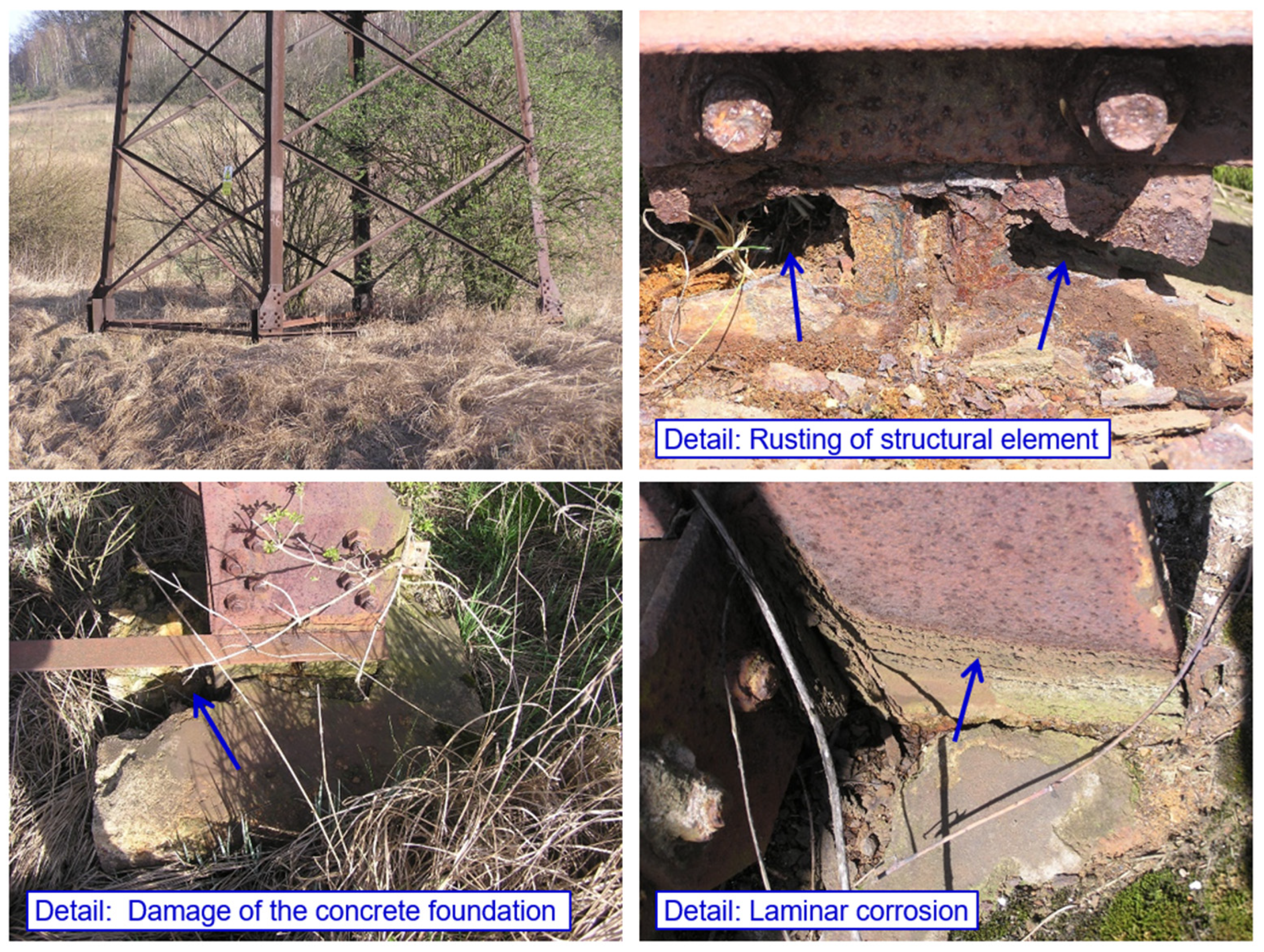
- Anchoring the structure to concrete foundations;
- Bolted joints of leg members.
2. Materials and Methods
2.1. Loading Tests of Bolted Joints
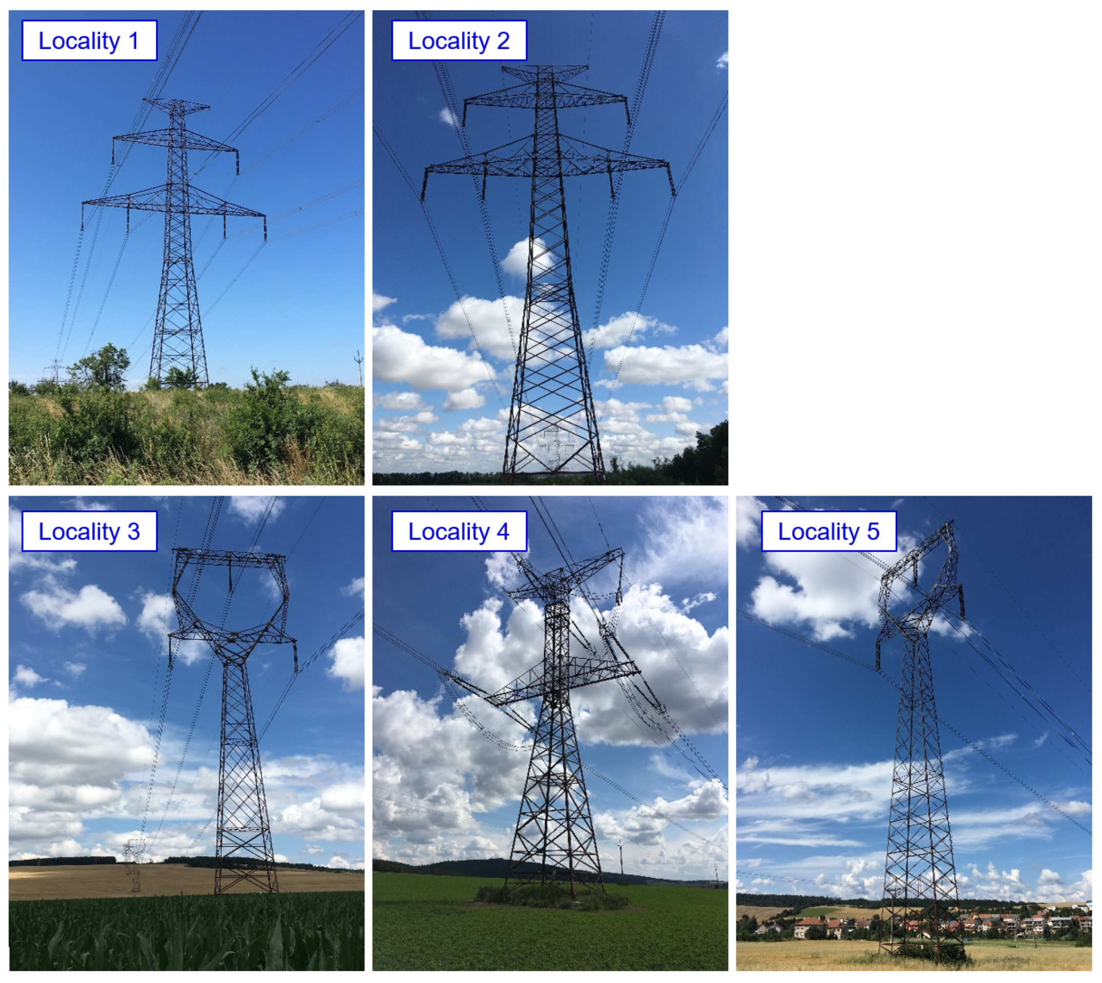
2.2. Assessment of the Technical Condition of the Transmission Towers in Operation
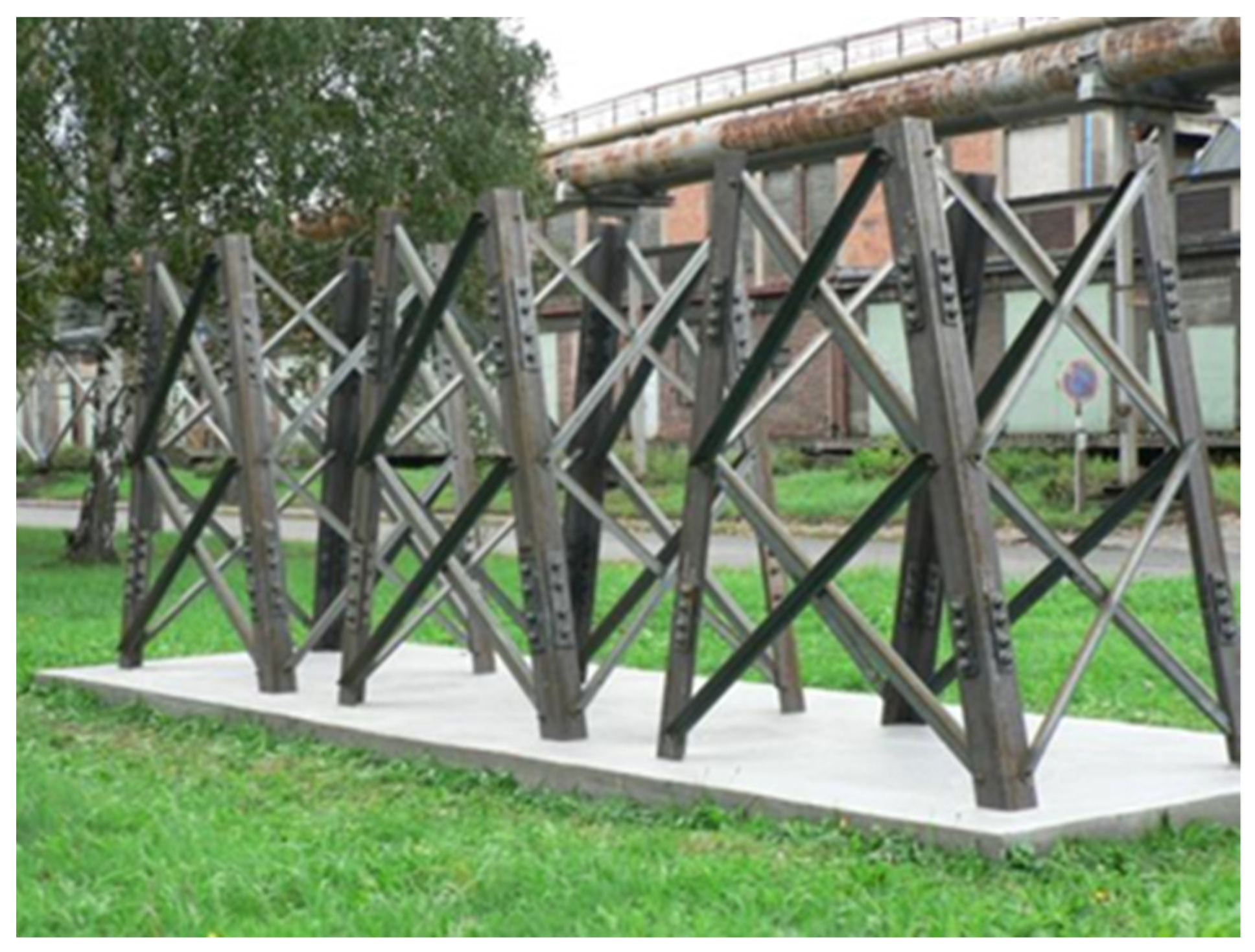
2.3. Experimental Lattice Towers
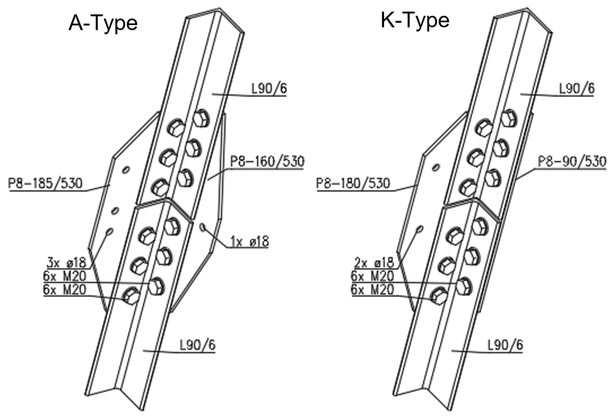
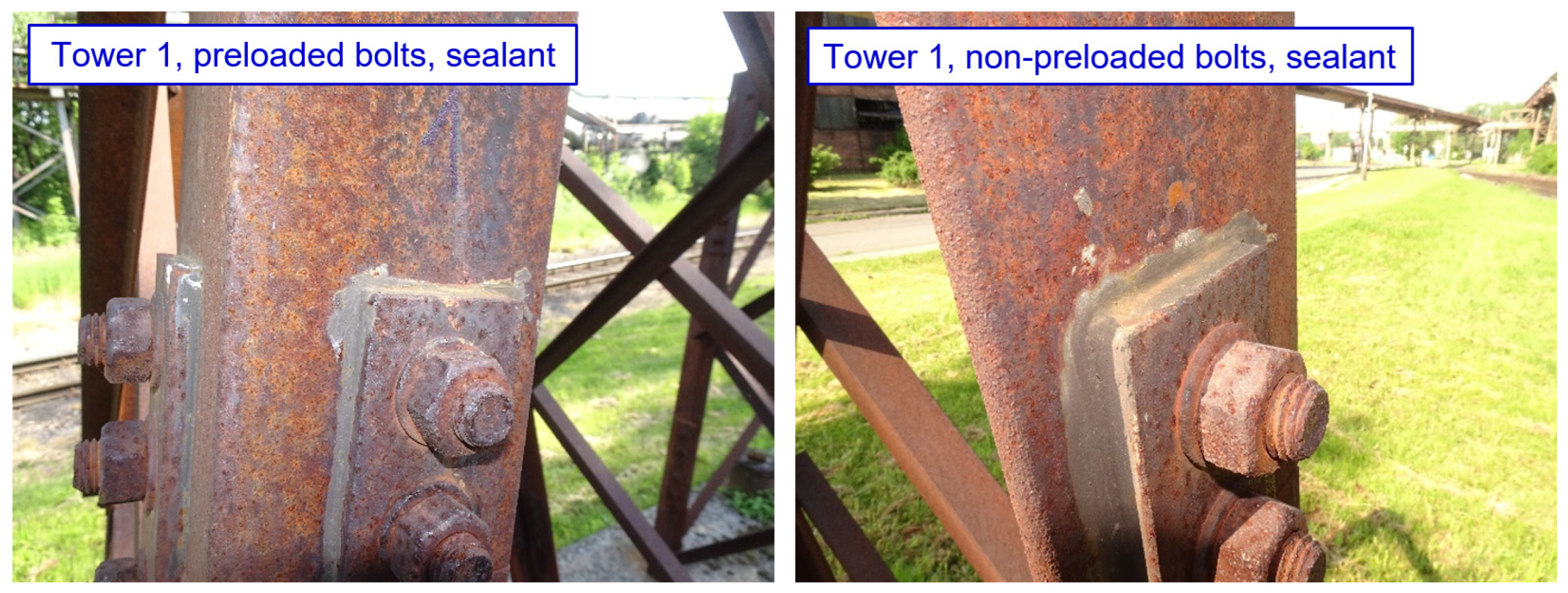
- The effect of spacings between centres of fasteners and of end, and edge, distances from the centre of a fastener in the connection. Connections with the minimum allowable spacing and end/edge distances were expected to be less susceptible to crevice corrosion. Therefore, for tower 1, all splices were designed with smaller spacings and end/edge distances, compared to towers 2 and 3 (for tower 1, the minimum permissible values were chosen in accordance with EN 1993-1-8).
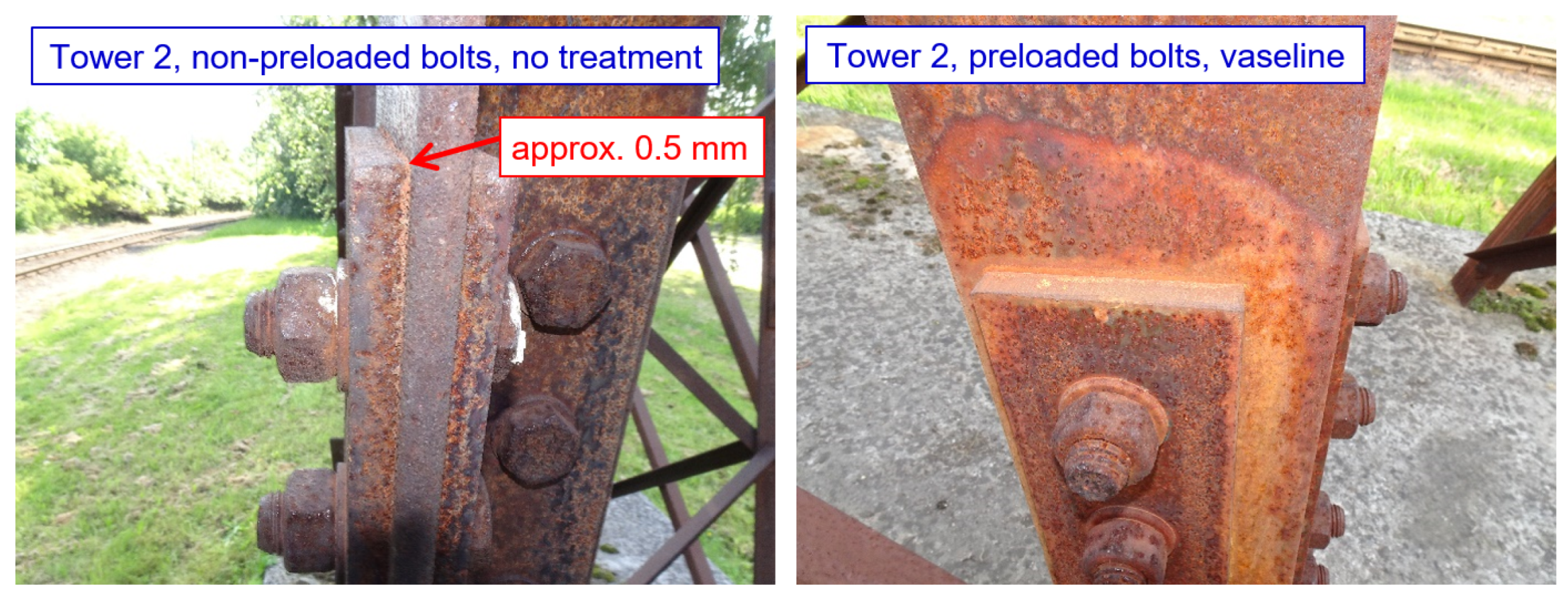
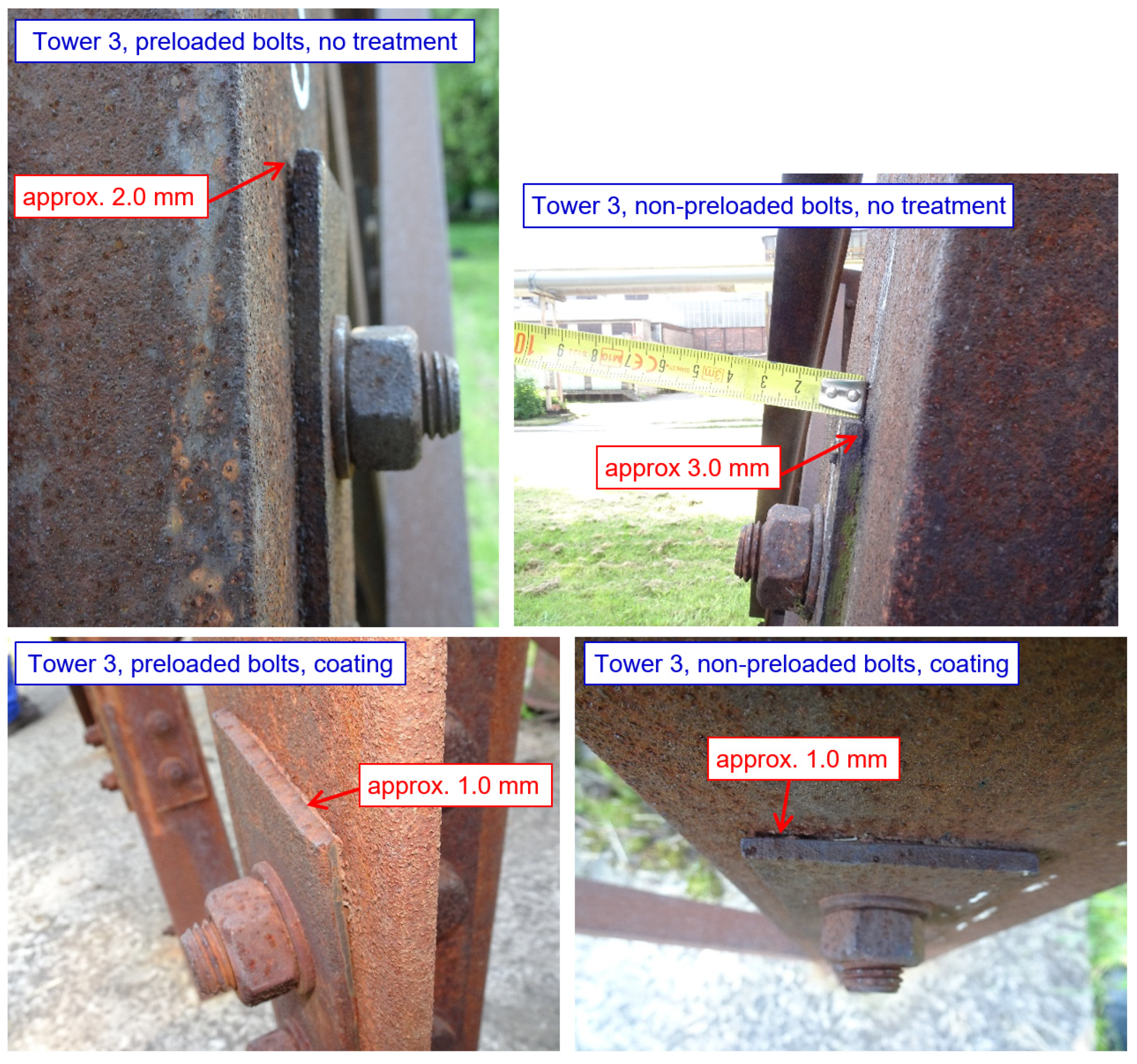
- The effect of the thickness of the splice. It was assumed that joints with thicker splices are less susceptible to crevice corrosion. On towers 1 and 2, all splices were designed with a nominal thickness of t = 10 mm, and on tower 3 the splices were designed with a nominal thickness of t = 5 mm.
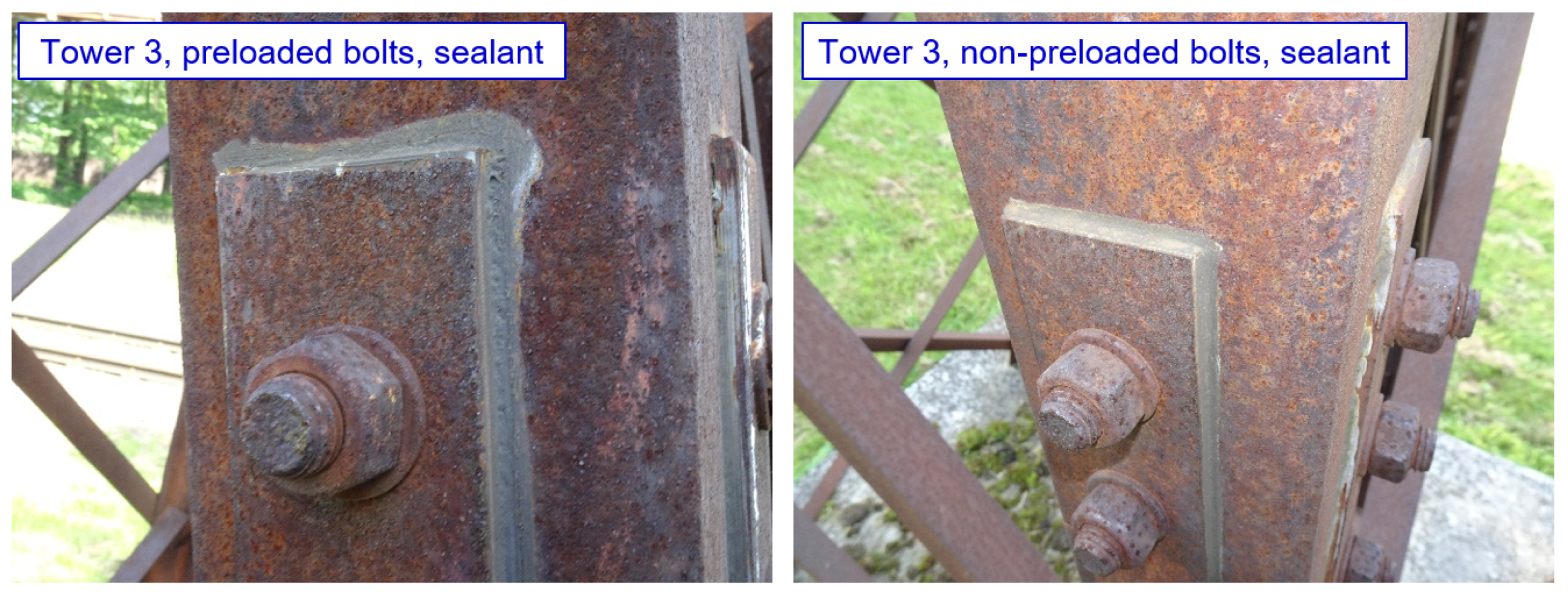
- The effect of bolt preloading. Joints with preloaded bolts were expected to be less susceptible to crevice corrosion. Half of the bolted joints on each tower included preloaded bolts (uncoated M20 bolts, strength class 8.8, bolt shank coated with Teflon Vaseline M8062, tightening moment 400 Nm).
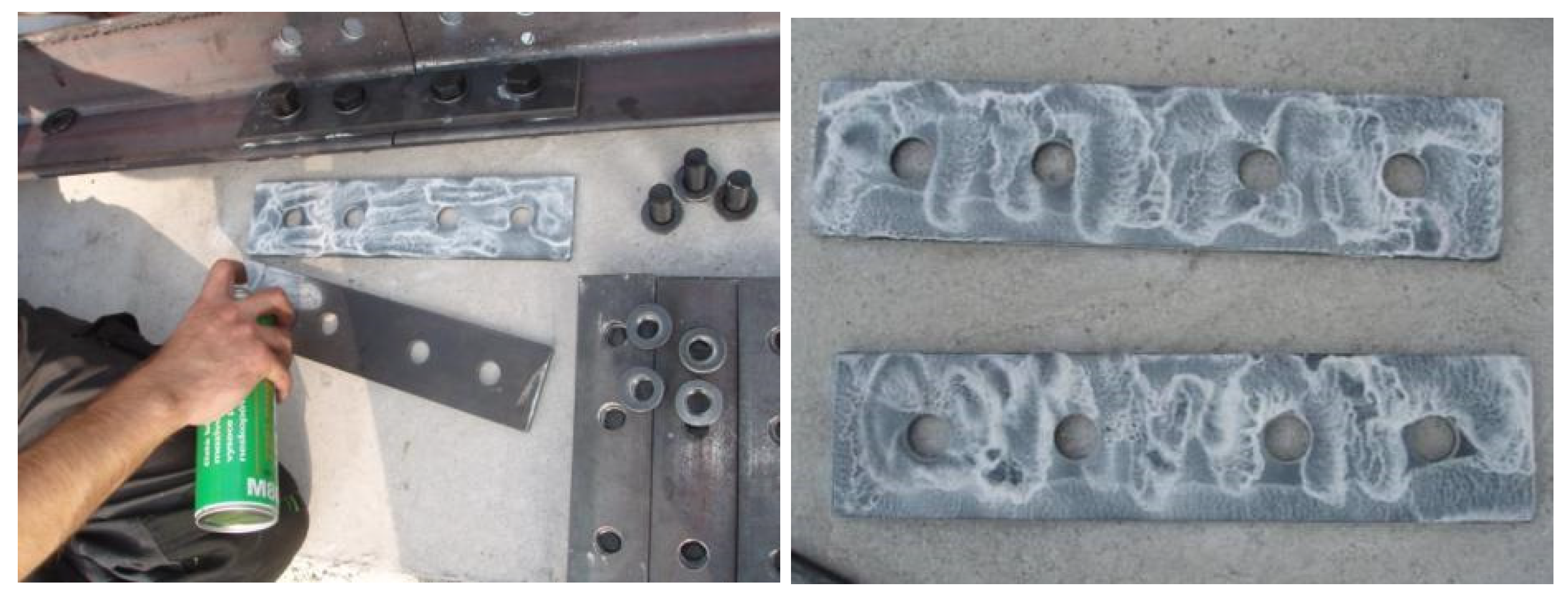
- The effect of treatment of the contact surface of the splices and leg members. It was assumed that connections with treated contact surfaces are less susceptible to crevice corrosion. Four types of contact surfaces were tested—contact surface of splices without treatment, contact surface of splices with paint (FEST-B S2141 paint), contact surface of splices with silicone sealant (neutral silicone OXIM; the method of application of silicone sealant is documented in Figure 8), and the contact surface of splices with Vaseline (Teflon Vaseline M8062; the method of application of Teflon Vaseline is illustrated in Figure 9). There are always two joints on each lattice tower with the appropriate contact surface treatment—one joint with non-preloaded bolts, the other joint with preloaded bolts.
3. Results
3.1. Loading Tests of Bolted Joints
3.1.1. Calculation of the Resistance of the Bolted Connection
- Angle subjected to tension (calculation of Npl,Rd and Nu,Rd for the angle);
- Contact splices subjected to tension (calculation of Npl,Rd and Nu,Rd for the splices);
- Block tearing of a bolt group out of the angle (calculation of Veff,2,Rd);
- Bolts subjected to shear (calculation of Fv,Rd and Fb,Rd).
3.1.2. Analytical Calculation of the Tensile Force in Bolts Due to Pressure of Corrosion Products in the Crevice
3.1.3. Results of Loading Tests
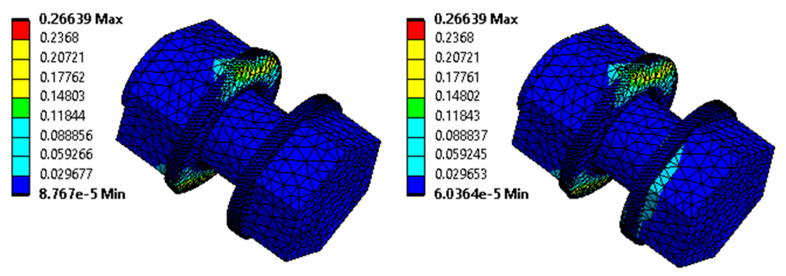
3.1.4. Results of Numerical Models
3.2. Assessment of the Technical Condition of the Transmission Towers in Operation
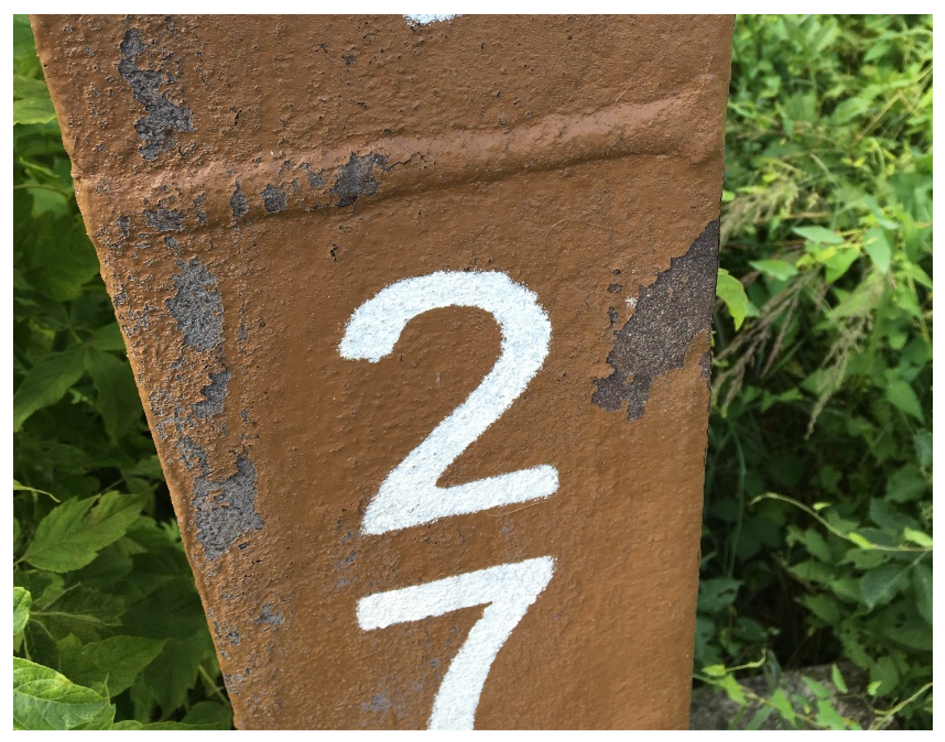
3.2.1. Development of Corrosion Products on Leg Members and Diagonals
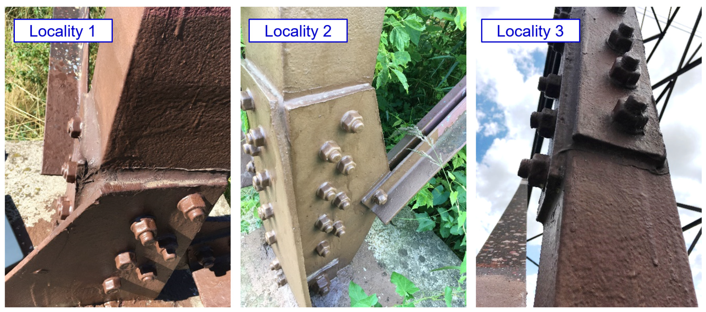
3.2.2. The Bolted Joints of the Leg Members
3.3. Experimental Lattice Towers
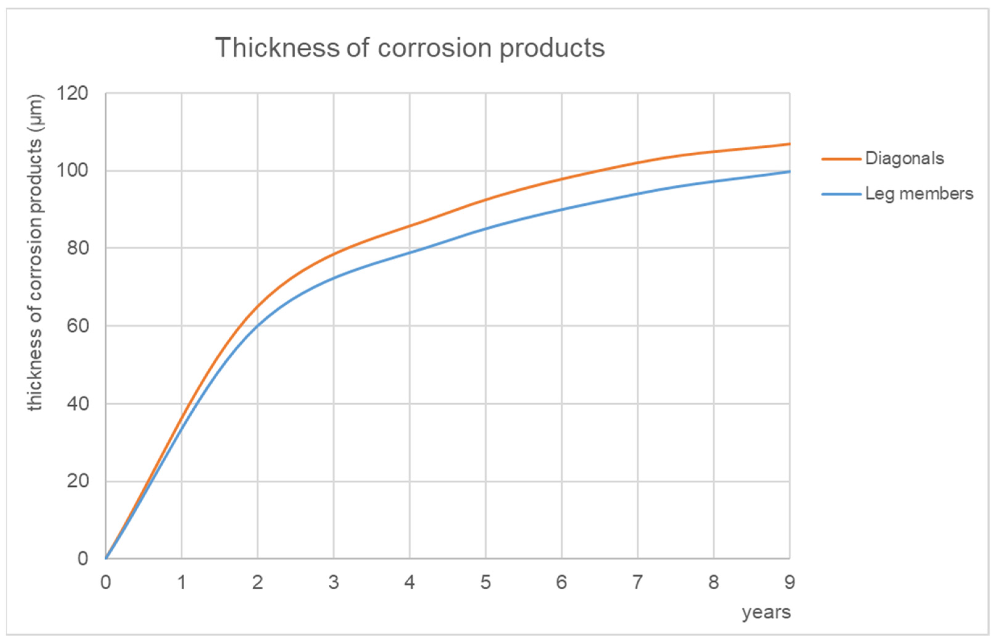
3.3.1. Development of Corrosion Products on Leg Members and Diagonals
3.3.2. The Bolted Joints of the Leg Members
4. Discussion
- Verification of the static resistance of bolted joints where crevice corrosion has already developed;
- Design and long-term verification of structural measures that eliminate the occurrence or further development of crevice corrosion in the long term.
4.1. Verification of the Static Resistance of Bolted Joints
- The shear and bearing resistance of the bolts will be minimally affected, because the bolt shank is located inside the connection, and the corrosion weakening of the bolt head and nut does not have a significant effect on the way the leg members are stressed.
- The greatest corrosion damage to the splices is expected in the gross cross-section between the bolts. However, the splices satisfy the resistance criterions with a margin in this cross-section, because they are not weakened by the bolt hole. In the net cross-section at the bolt, the effect of corrosion is less than in the cross-section between the bolts, due to the bolt tightening the crevice. The results of residual thickness measurements in the joint are found in [17], and the least corrosion weakening was found in the circumference of bolt holes.
- The corrosion weakening of the leg members designed from angles is similar to that of the contact splices. As a result of the smaller cross-sectional area, and the smaller thickness of the leg member, this effect may be more pronounced than for splices, and should always be assessed according to the specific condition of the towers. Therefore, the angle of the leg member is likely to remain the weakest component of the joint when considering corrosion weakening.
4.2. Design Solutions for New Transmission Towers
4.3. Recommended Method of Rehabilitation of Bolt Joints of the Leg Members
- The removal of corrosion products. The crevice between the splice and the web is cleaned of corrosion products to a minimum depth equal to the thickness of the crevice. Cleaning of the external surfaces around the connection is carried out by manual cleaning, or by cleaning with small machinery. In accessible locations, cleaning by blasting, such as high-speed blasting with thermo-blast technology, is recommended to remove corrosion products instead of manual cleaning.
- The application of the primer, with an overlap of up to 200 mm from the edge of the connection.
- Sealing the joint. First, it is necessary to seal the inner space of the scratched crevice, then the space between the splice and the leg member is sealed and smoothed, so that the sealant is evenly distributed and does not overlap the splice.
- Cover the sealant and the overlap from the edge of the connection with a coating (primer and topcoat).
5. Conclusions
- The capacity of the bolted joint of the leg member is not significantly affected by the development of corrosion products in the crevice, provided that higher strength bolts (8.8 or 10.9) are used, and no significant corrosion weakening of the corner bolt occurs. This finding was verified both by tensile tests on specimens taken from actually operated transmission lattice towers, and by analytical and numerical calculations and static assessments.
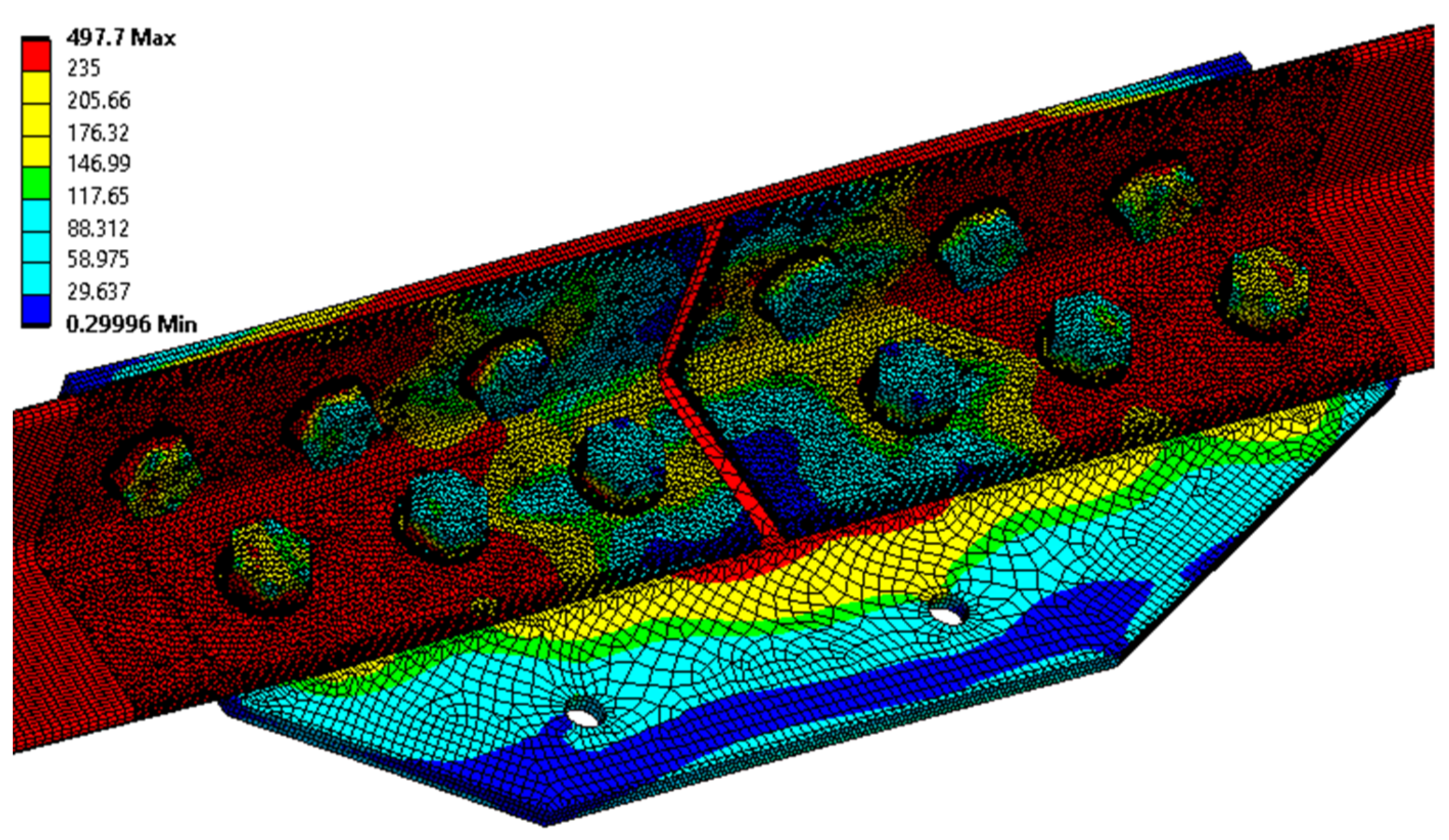
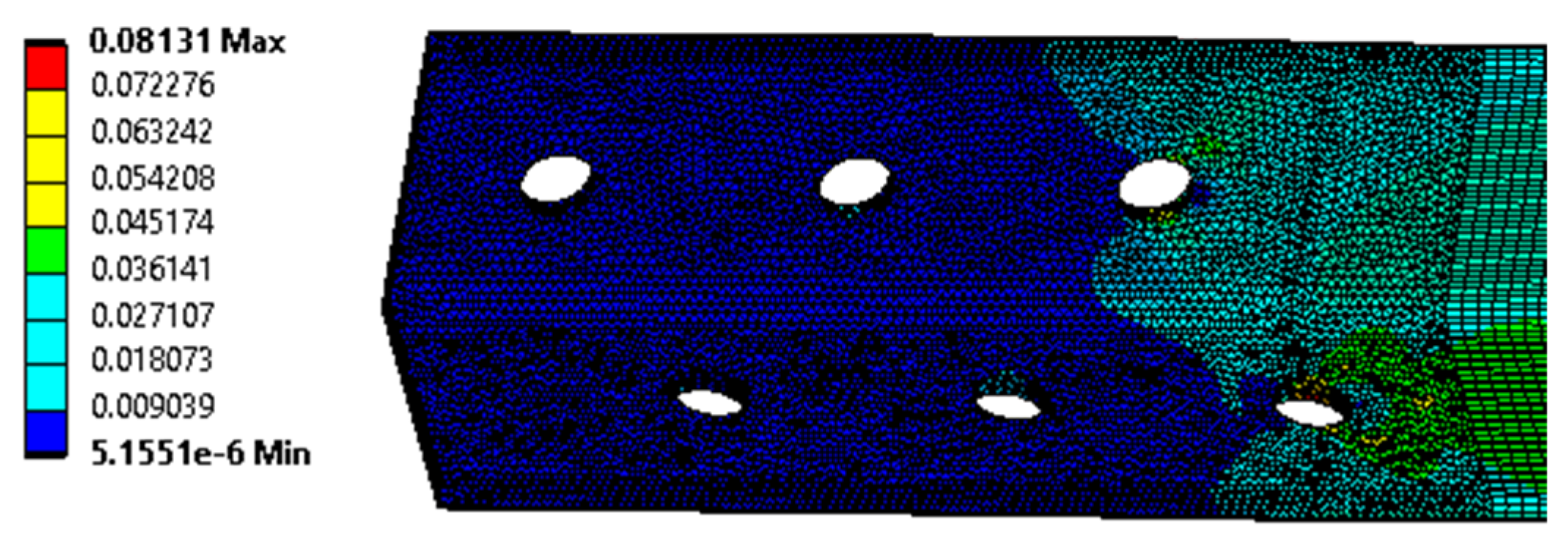
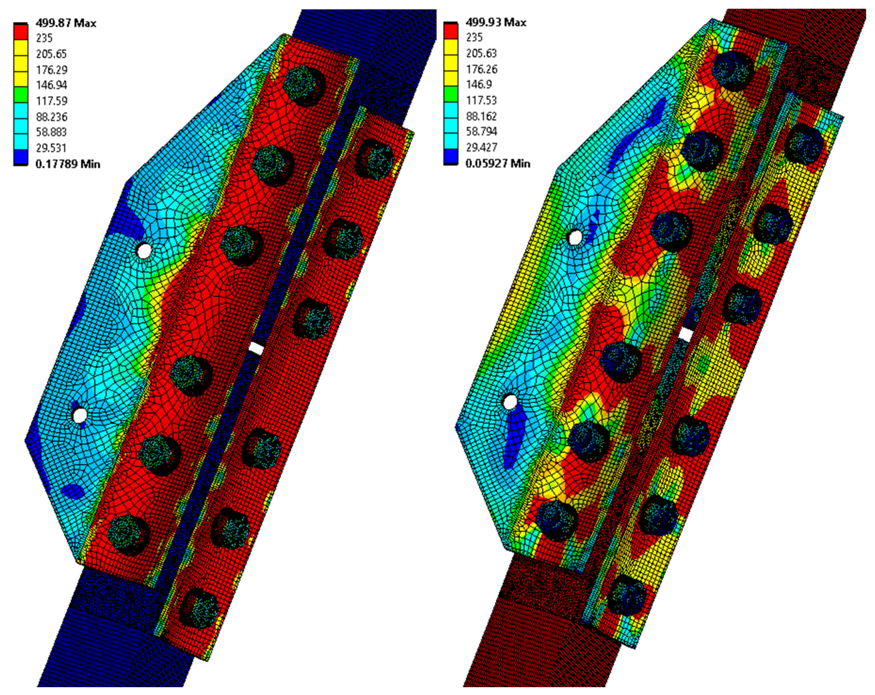
- Using analytical or numerical models, it is possible to determine the static resistance of the joint affected by crevice corrosion with sufficient accuracy. Both calculation procedures given in Section 3.1.1 and Section 3.1.4 can be used in the assessment of structures.
- The basic design measure is the design of sufficiently rigid splices. It is advisable to design the minimum recommended values for bolt spacing, and the end and edge distances. It is recommended to preload the bolts. This structural recommendation is supported by the results of long-term testing using experimental lattice towers.
- The application of silicone sealant seems to be the appropriate measure. The measure is effective in the long term, simple to apply, and also relatively cheap. The suitability of this measure is verified for new towers, and also for the rehabilitation of bolted joints in lattice structures in operation.
Author Contributions
Funding
Institutional Review Board Statement
Informed Consent Statement
Data Availability Statement
Conflicts of Interest
References
- Lebet, J.P.; Lang, T.P. Brücken Aus Wetterfestem Stahl; ICOM Construction Métallique, EPFL: Lausanne, Switzerland, 2001. [Google Scholar]
- Morcillo, M.; Díaz, I.; Chico, B.; Cano, H.; de la Fuente, D. Weathering steels: From empirical development to scientific design. A review. Corros. Sci. 2014, 83, 6–31. [Google Scholar] [CrossRef] [Green Version]
- Morcillo, M.; Chico, B.; Díaz, I.; Cano, H.; de la Fuente, D. Atmospheric corrosion data of weathering steels. A review. Corros. Sci. 2013, 77, 6–24. [Google Scholar] [CrossRef] [Green Version]
- Albrecht, P.; Naeemi, A. Performance of Weathering Steel in Bridges; NCHRP: Washington, DC, USA, 1984. [Google Scholar]
- Bupesh Raja, V.K.; Palanikumar, K.; Renish, R.R.; Ganesh Babu, A.N.; Varma, J.; Gopal, P. Corrosion resistance of corten steel—A review. Mater. Today Proc. 2021, 46, 3572–3577. [Google Scholar] [CrossRef]
- Kocich, J.; Ševčíková, J.; Tuleja, S. Effect of atmospheric corrosion on the mechanical properties of the weathering steel Atmofix 52A. Corros. Sci. 1993, 35, 719–725. [Google Scholar] [CrossRef]
- Ungermann, D.; Hatke, P. European Design Guide for the Use of Weathering Steel in Bridge Construction, 2nd ed.; ECCS A3 Bridge Committee: Brussels, Belgium, 2021. [Google Scholar]
- McConnell, J.; Shenton, H.W.; Mertz, D.R.; Kaur, D. Performance of Uncoated Weathering Steel Highway Bridges Throughout the United States. Transp. Res. Rec. 2014, 2406, 61–67. [Google Scholar] [CrossRef]
- CD 361 Weathering Steel for Highway Structures; Highways England: London, UK, 2019.
- Rigueiro, C.; Jehlička, P.; Ryjáček, P.; Wald, F. Life Cycle Assessment of Steel Concrete Bridges I. General Issues and Examples; CTU in Prague: Prague, Czech Republic, 2018. (In Czech) [Google Scholar]
- Goto, H.; Moriya, S.; Naitoh, Y.; Yamamoto, M.; Fujishiro, M.; Saito, M. Examination of Repairing Methods of Weathering Steel by Painting. Zair. Kankyo 2010, 59, 10–17. [Google Scholar] [CrossRef] [Green Version]
- Lambert, P. 6-Sustainability of metals and alloys in construction. In Woodhead Publishing Series in Civil and Structural Engineering; CRC Press Inc.: Boca Raton, FL, USA, 2016; pp. 105–128. [Google Scholar]
- Targowski, W.; Kulowski, A. Influence of the Widespread Use of Corten Plate on the Acoustics of the European Solidarity Centre Building in Gdańsk. Buildings 2021, 11, 133. [Google Scholar] [CrossRef]
- EN 1993-3-1; Eurocode 3: Design of Steel Structures—Part 3-1: Towers, Masts and Chimneys—Towers and Masts. CEN: Brussels, Belgium, 2006.
- Shangwu, Z.; Delu, X.; Daijun, L.; Guang, L.; Jianwei, C.; Chao, F. A study on weathering steel bolts for transmission towers. J. Constr. Steel Res. 2020, 174, 106295. [Google Scholar]
- Brockenbrough, R.L.; Schmitt, R.J. Considerations in the performance of bare high-strength low-alloy steel transmission towers. IEEE Trans. Power Appar. Syst. 1975, 94, 1–6. [Google Scholar]
- Knotkova, D.; Vlckova, J. Atmospheric Corrosion of Bolted Lap Joints Made of Weathering Steel; ASTM Special Technical Publications: West Conshohocken, PA, USA, 1995; pp. 114–136. [Google Scholar]
- Kreislova, K.; Geiplova, H.; Mindos, L.; Novakova, R. Corrosion Protection of Infrastructure of Power Industry. Mater. Sci. Forum. 2015, 811, 31–40. [Google Scholar] [CrossRef]
- Krivy, V.; Urban, V.; Kreislova, K. Development and failures of corrosion layers on typical surfaces of weathering steel bridges. Eng. Fail. Anal. 2016, 69, 147–160. [Google Scholar] [CrossRef]
- Krivy, V.; Kubzova, M.; Kreislova, K.; Urban, V. Characterization of corrosion products on weathering steel bridges influenced by chloride deposition. Metals 2017, 7, 336. [Google Scholar] [CrossRef] [Green Version]
- Kelly, R.G.; Lee, J.S. Localized Corrosion: Crevice Corrosion. Encyclopedia of Interfacial Chemistry. In Encyclopedia of Interfacial Chemistry; Elsevier: Amsterdam, The Netherlands, 2018; pp. 291–301. ISBN 9780128098943. [Google Scholar]
- Jones, D.A.; Wilde, B.E. Effect of Alternating Current on the Atmospheric Corrosion of Low-Alloy Weathering Steel in Bolted Lap Joints. Corrosion 1987, 43, 66–70. [Google Scholar] [CrossRef]
- Leygraf, C.; Wallinder, I.O.; Tidblad, J.; Graedel, T. Atmospheric Corrosion, 2nd ed.; John Wiley & Sons, Inc.: Hoboken, NJ, USA, 2016. [Google Scholar]
- EN 1993-1-1; Eurocode 3: Design of Steel Structures—Part 1–1: General Rules and Rules for Buildings. CEN: Brussels, Belgium, 2006.
- EN 1993-1-8; Eurocode 3: Design of Steel Structures—Part 1–8: Design of Joints. CEN: Brussels, Belgium, 2006.
- Ye, J.; Quan, G.; Yun, X.; Guo, X.; Chen, J. An improved and robust finite element model for simulation of thin-walled steel bolted connections. Eng. Struct. 2022, 250, 113368. [Google Scholar] [CrossRef]
- Belardi, V.G.; Fanelli, P.; Vivio, F. Theoretical definition of a new custom finite element for structural modeling of composite bolted joints. Compos. Struct. 2021, 258, 113199. [Google Scholar] [CrossRef]
- McCarthy, M.A.; McCarthy, C.T.; Lawlor, V.P.; Stanley, W.F. Three-dimensional finite element analysis of single-bolt, single-lap composite bolted joints: Part I—Model development and validation. Compos. Struct. 2005, 71, 140–158. [Google Scholar] [CrossRef]
- Albrecht, P.; Hall, T.T. Atmospheric corrosion resistance of structural steels. J. Mater. Civ. Eng. 2003, 15, 2–24. [Google Scholar] [CrossRef]
- Wang, Z.; Liu, J.; Wu, L.; Han, R.; Sun, Y. Study of the corrosion behavior of weathering steels in atmospheric environments. Corros. Sci. 2013, 67, 1–10. [Google Scholar] [CrossRef]
- Raman, A.; Nasrazadani, S.; Sharma, L. Morphology of rust phases formed on weathering steels in various laboratory corrosion tests. Metallography 1989, 22, 79–96. [Google Scholar] [CrossRef]
- Guo, X.; Zhu, J.; Kang, J.; Duan, M.; Wang, Y. Rust layer adhesion capability and corrosion behavior of weathering steel under tension during initial stages of simulated marine atmospheric corrosion. Constr. Build. Mater. 2020, 234, 117393. [Google Scholar] [CrossRef]
- Strieška, M.; Koteš, P. Sensitivity of dose-response function for carbon steel under various conditions in Slovakia. Transp. Res. Procedia 2019, 40, 912–919. [Google Scholar] [CrossRef]
- ČSN 41 5217; Steel Cr-Ni-Cu-P (National Standard). Office for Standards and Measurements: Prague, Czech Republic, 1986. (In Czech)
- EN 10025-5; Hot Rolled Products of Structural Steels—Part 5: Technical Delivery Conditions for Structural Steels with Improved Atmospheric Corrosion Resistance. CEN: Brussels, Belgium, 2020.
- Rozlívka, L.; Melcher, J. Loading Tests of Bolted Joints of Lattice Transmission Towers Made of Atmofix Steel; Research Report; Institute of Steel Structures, Ltd.: Frýdek Místek, Czech Republic; Brno University of Technology: Brno, Czech Republic, 2001. (In Czech) [Google Scholar]
- EN ISO 6892-1; Metallic Materials—Tensile Testing—Part 1: Method of Test at Room Temperature. CEN: Brussels, Belgium, 2021.
- Ramberg, W.; Osgood, W.R. Description of Stress–Strain Curves by Three Parameters; Technical Note No. 902; National Advisory Committee for Aeronautics: Washington, DC, USA, 1943. [Google Scholar]
- ASTM G101-04:2020; Standard Guide for Estimating the Atmospheric Corrosion Resistance of Low-Alloy Steels. ASTM International: West Conshohocken, PA, USA, 2020.
- Krivy, V.; Konecny, P. Real material properties of weathering steels used in bridge structures. Procedia Eng. 2013, 57, 624–633. [Google Scholar] [CrossRef] [Green Version]
- Yamaguchi, E. Maintenance of weathering steel bridges. Steel Constr. Today Tomorrow 2015, 45, 12–15. [Google Scholar]
- Krivy, V.; Kreislova, K.; Rozlivka, L.; Knotkova, D. Guidelines for the Use of Steels with Improved Atmospheric Corrosion Resistance; Czech Constructional Steelwork Association: Ostrava, Czech Republic, 2011. (In Czech) [Google Scholar]
- Krejslova, K.; Knotkova, D. The Results of 45 Years of Atmospheric Corrosion Study in the Czech Republic. Materials 2017, 10, 394. [Google Scholar] [CrossRef] [PubMed] [Green Version]
- Holický, M.; Viljoen, C.; Retlief, J.V. Assessment of existing structures. In Advances in Engineering Materials, Structures and Systems: Innovations, Mechanics and Applications; CRC Press: London, UK, 2019. [Google Scholar]






| Standard Test Piece | C | Mn | Si | P | S | Cu | Ni | Cr |
|---|---|---|---|---|---|---|---|---|
| EN 10025-5 | max 0.19 | 0.45 1.60 | max 0.55 | max 0.35 | max 0.030 | 0.20 0.60 | max 0.70 | 0.35 0.85 |
| CSN 41 5217 | max 0.14 | 0.25 1.10 | 0.22 0.85 | 0.06 0.18 | max 0.040 | 0.25 0.60 | 0.25 0.65 | 0.45 1.35 |
| Leg member No. 1 (L90x6) | 0.103 | 0.48 | 0.481 | 0.103 | 0.012 | 0.397 | 0.486 | 0.849 |
| Leg member No. 2 (L90x6) | 0.107 | 0.56 | 0.499 | 0.100 | 0.018 | 0.481 | 0.408 | 0.702 |
| Splice No. 1 (P8) | 0.111 | 0.59 | 0.378 | 0.091 | 0.009 | 0.367 | 0.378 | 0.810 |
| Standard Test Piece | Yield Strength ReH (MPa) | Tensile Strength Rm (MPa) | Extension A5 (%) |
|---|---|---|---|
| EN 10025-5 | 355 | 470–630 | 22 |
| CSN 41 5217 | 355 | 490–630 | 22 |
| Leg member No. 1 (L90x6) | 420 | 504 | 29.2 |
| Leg member No. 2 (L90x6) | 402 | 529 | 29.9 |
| Leg member No. 3 (L90x6) | 379 | 500 | 28.8 |
| Leg member No. 4 (L90x6) | 375 | 524 | 24.3 |
| Leg member No. 5 (L90x6) | 376 | 517 | 25.0 |
| Splice No. 1 (P8) | 355 | 505 | 26.5 |
| Splice No. 2 (P8) | 385 | 515 | 34.0 |
| Splice No. 3 (P8) | 359 | 497 | 26.9 |
| minimum measured value | 355 | 497 | 24.3 |
| average of measured values | 381.4 | 511.4 | 28.1 |
| maximum measured value | 420 | 529 | 34.0 |
| Fe | Cu | Ni | Mn | Cr | P | S | C |
| 36.53 | 0.04 | 0.08 | 0.47 | 0.05 | 0.42 | 1.61 | 16.40 |
| O | Na | Mg | Al | Si | Cl | K | Ca |
| 38.60 | 0.83 | 0.80 | 1.20 | 2.13 | 0.26 | 0.39 | 0.19 |
| Fe | Cu | Ni | Mn | Cr | P | S | C |
| 13.86 | 0.01 | 0.03 | 0.18 | 0.02 | 0.29 | 1.06 | 28.94 |
| O | Na | Mg | Al | Si | Cl | K | Ca |
| 51.12 | 0.77 | 0.70 | 0.94 | 1.61 | 0.16 | 0.21 | 0.10 |
| C | Mn | Si | P | S | Cu | Ni | Cr | Al | V | N |
| 0.11 | 1.00 | 0.21 | 0.11 | 0.007 | 0.33 | 0.17 | 0.49 | 0.030 | 0.04 | 0.011 |
| Yield Strength ReH | Tensile Strength Rm | Extension A5 | Impact Strength KV 7.5 mm (J) | ||
|---|---|---|---|---|---|
| (MPa) | (MPa) | (%) | T = 0 °C | T = −20 °C | T = −50 °C |
| 427 | 541 | 29.7 | 189 | 157 | 71 |
| Yield Strength ReH | Tensile Strength Rm | Extension A5 | Impact Strength KV 7.5 mm (J) | ||
|---|---|---|---|---|---|
| (MPa) | (MPa) | (%) | T = 0 °C | T = −20 °C | T = −50 °C |
| 419 | 553 | 32.9 | 79 | 50 | - |
| Member | Yield Strength ReH | Tensile Strength Rm | Extension A5 | Impact Strength KV 7.5 mm (J) | ||
|---|---|---|---|---|---|---|
| (MPa) | (MPa) | (%) | T = 0 °C | T = −20 °C | T = −50 °C | |
| P80 × 10 | 409 | 544 | 29.7 | 194 | 180 | - |
| P60 × 10 | 395 | 574 | 30.3 | 184 | 166 | - |
| L80 × 5 | 438 | 558 | 28.9 | 83 | 65 | - |
| Test Specimen | Fmax 1 (kN) | umax 2 (mm) | Fel 3 (kN) | uel 4 (mm) | Failure Mode |
|---|---|---|---|---|---|
| A1 | 462 | 18.3 | ~350 | 6.4 | rupture of the angle |
| A2 | 452 | 25.5 | 10.5 | ||
| A3 | 468 | 22.4 | 11.2 | ||
| K1 | 484 | 26.6 | 11.2 | ||
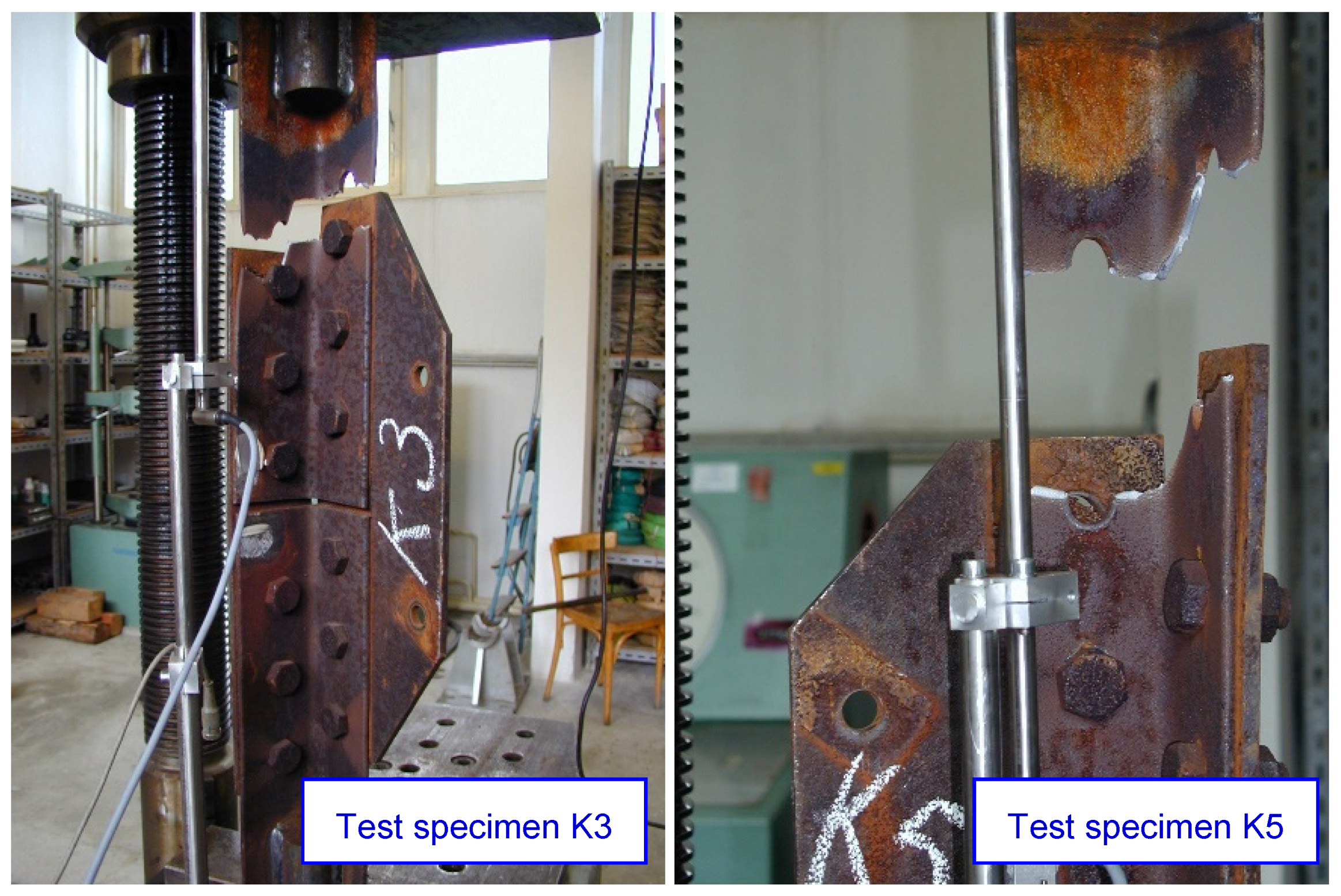
| K2 | 475 | 15.0 | 4.6 | failure of the bolts | |
| K3 | 472 | 25.1 | 12.4 | rupture of the angle | |
| K4 | 481 | 27.2 | 10.4 | ||
| K5 | 441 | 16.6 | 5.8 | ||
| minimum | 441.0 | 15.0 | N/A | 4.6 | N/A |
| average | 466.9 | 22.1 | 9.1 | ||
| maximum | 484.0 | 27.2 | 12.4 |
| Locality | Member | n | Mean (μm) | Std (μm) | Min (μm) | Max (μm) |
|---|---|---|---|---|---|---|
| Locality 1 GPS: 48.8226420N, 16.1303896E | leg member | 30 | 161.0 | 37.8 | 110 | 226 |
| leg member | 30 | 151.1 | 30.5 | 88 | 196 | |
| diagonal | 30 | 138.3 | 39.8 | 72 | 254 | |
| diagonal | 30 | 139.5 | 29.0 | 74 | 194 | |
| Locality 2 GPS: 48.7637931N, 16.0989825E | leg member | 30 | 197.7 | 50.8 | 102 | 316 |
| leg member | 30 | 157.1 | 42.5 | 90 | 270 | |
| Locality 3 GPS: 49.1171492N, 16.3673119E | leg member | 30 | 167.3 | 47.2 | 94 | 298 |
| leg member | 30 | 157.1 | 26.4 | 100 | 190 | |
| diagonal | 30 | 178.2 | 42.0 | 108 | 286 | |
| diagonal | 30 | 136.3 | 32.0 | 80 | 192 | |
| diagonal | 30 | 194.0 | 42.7 | 130 | 292 | |
| Locality 4 GPS: 49.1847531N, 16.4080061E | leg member | 30 | 165.1 | 32.1 | 114 | 226 |
| leg member | 30 | 194.0 | 40.8 | 116 | 282 | |
| diagonal | 30 | 150.6 | 29.9 | 104 | 218 | |
| diagonal | 30 | 146.9 | 27.5 | 102 | 192 | |
| diagonal | 30 | 148.9 | 26.7 | 100 | 206 | |
| Locality 5 GPS: 49.2328666N, 16.4083097E | leg member | 30 | 170.5 | 34.7 | 110 | 244 |
| leg member | 30 | 161.8 | 35.4 | 112 | 254 | |
| diagonal | 30 | 154.7 | 27.1 | 118 | 230 | |
| diagonal | 30 | 149.9 | 35.2 | 102 | 238 |
Publisher’s Note: MDPI stays neutral with regard to jurisdictional claims in published maps and institutional affiliations. |
© 2022 by the authors. Licensee MDPI, Basel, Switzerland. This article is an open access article distributed under the terms and conditions of the Creative Commons Attribution (CC BY) license (https://creativecommons.org/licenses/by/4.0/).
Share and Cite
Křivý, V.; Vašek, Z.; Vacek, M.; Mynarzová, L. Corrosion Damage to Joints of Lattice Towers Designed from Weathering Steels. Materials 2022, 15, 3397. https://doi.org/10.3390/ma15093397
Křivý V, Vašek Z, Vacek M, Mynarzová L. Corrosion Damage to Joints of Lattice Towers Designed from Weathering Steels. Materials. 2022; 15(9):3397. https://doi.org/10.3390/ma15093397
Chicago/Turabian StyleKřivý, Vít, Zdeněk Vašek, Miroslav Vacek, and Lucie Mynarzová. 2022. "Corrosion Damage to Joints of Lattice Towers Designed from Weathering Steels" Materials 15, no. 9: 3397. https://doi.org/10.3390/ma15093397
APA StyleKřivý, V., Vašek, Z., Vacek, M., & Mynarzová, L. (2022). Corrosion Damage to Joints of Lattice Towers Designed from Weathering Steels. Materials, 15(9), 3397. https://doi.org/10.3390/ma15093397


