
Pressure Drop Performance of Porous Composites Based on Cotton Cellulose Nanofiber and Aramid Nanofiber for Cigarette Filter Rod

 ,
,
Abstract
:1. Introduction
2. Experimental Section
2.1. Synthesis of Cotton Cellulose Nanofiber/Aramid Nanofiber Hydrogel
2.2. Synthesis of Porous Cellulose Nanofiber/Aramid Nanofiber Cigarette Filter Rod
2.3. Characterization
3. Results and Discussion
4. Conclusions
Author Contributions
Funding
Institutional Review Board Statement
Informed Consent Statement
Data Availability Statement
Conflicts of Interest
References
- Matsuda, Y.; Ookawara, S.; Yasuda, T.; Yoshikawa, S.; Matsumoto, H. Framework for discovering porous materials: Structural hybridization and Bayesian optimization of conditional generative adversarial network. Digit. Chem. Eng. 2022, 5, 100058. [Google Scholar] [CrossRef]
- Yasuda, T.; Ookawara, S.; Yoshikawa, S.; Matsumoto, H. Materials processing model-driven discovery framework for porous materials using machine learning and genetic algorithm: A focus on optimization of permeability and filtration efficiency. Chem. Eng. J. 2023, 453, 139540. [Google Scholar] [CrossRef]
- Diaz-Marin, C.D.; Zhang, L.; Lu, Z.; Alshrah, M.; Grossman, J.C.; Wang, E.N. Kinetics of Sorption in Hygroscopic Hydrogels. Nano Lett. 2022, 22, 1100–1107. [Google Scholar] [CrossRef] [PubMed]
- Ding, M.; Liu, X.; Ma, P.; Yao, J. Porous materials for capture and catalytic conversion of CO2 at low concentration. Coord. Chem. Rev. 2022, 465, 214576. [Google Scholar] [CrossRef]
- Chen, Y.; Xia, L.; Li, G. The progress on porous organic materials for chiral separation. J. Chromatogr. A 2022, 1677, 463341. [Google Scholar] [CrossRef] [PubMed]
- Ji, X.; Zhao, J.; Jung, S.M.; Hrdina, A.I.H.; Wolf, M.J.; Yang, X.; Vaartstra, G.; Xie, H.; Luo, S.L.; Lu, A.Y.; et al. Bottom-Up Synthesized All-Thermal-Catalyst Aerogels for Heat-Regenerative Air Filtration. Nano Lett. 2021, 21, 8160–8165. [Google Scholar] [CrossRef]
- Li, S.; He, Y.; Ye, X.; Fu, X.; Hou, Y.; Tian, H.; Huang, J.; Gan, L. Improved piezoelectricity of porous cellulose material via flexible polarization-initiate bridge for self-powered sensor. Carbohydr. Polym. 2022, 298, 120099. [Google Scholar] [CrossRef]
- Shoeibi, S.; Saemian, M.; Kargarsharifabad, H.; Hosseinzade, S.; Rahbar, N.; Khiadani, M.; Rashidi, M.M. A review on evaporation improvement of solar still desalination using porous material. Int. Commun. Heat Mass Transf. 2022, 138, 106387. [Google Scholar] [CrossRef]
- Dashtbani, R.; Afra, E. Producing Cellulose nanofiber from Cotton wastes by electrospinning method. Int. J. Nano Dimens. 2015, 6, 1–9. [Google Scholar]
- Rustemeyer, P. 1. History of CA and evolution of the markets. Macromol. Symp. 2004, 208, 1–6. [Google Scholar] [CrossRef]
- Dobaradaran, S.; Schmidt, T.C.; Lorenzo-Parodi, N.; Jochmann, M.A.; Nabipour, I.; Raeisi, A.; Stojanovic, N.; Mahmoodi, M. Cigarette butts: An overlooked source of PAHs in the environment? Env. Pollut 2019, 249, 932–939. [Google Scholar] [CrossRef] [PubMed]
- Mazzotta, M.G.; Reddy, C.M.; Ward, C.P. Rapid Degradation of Cellulose Diacetate by Marine Microbes. Environ. Sci. Technol. Lett. 2021, 9, 37–41. [Google Scholar] [CrossRef]
- Maderuelo-Sanz, R.; Gómez Escobar, V.; Meneses-Rodríguez, J.M. Potential use of cigarette filters as sound porous absorber. Appl. Acoust. 2018, 129, 86–91. [Google Scholar] [CrossRef]
- Zhao, Z.; Guo, Y.; Zhang, T.; Ma, J.; Li, H.; Zhou, J.; Wang, Z.; Sun, R. Preparation of carbon dots from waste cellulose diacetate as a sensor for tetracycline detection and fluorescence ink. Int. J. Biol. Macromol. 2020, 164, 4289–4298. [Google Scholar] [CrossRef]
- Liu, H.; Chen, Y.; Xue, Y. Reutilization of Recycled Cellulose Diacetate From Discarded Cigarette Filters in Production of Stone Mastic Asphalt Mixtures. Front. Mater. 2021, 8, 770150. [Google Scholar] [CrossRef]
- Li, J.; Song, Z.; Li, D.; Shang, S.; Guo, Y. Cotton cellulose nanofiber-reinforced high density polyethylene composites prepared with two different pretreatment methods. Ind. Crops Prod. 2014, 59, 318–328. [Google Scholar] [CrossRef]
- Aruchamy, K.; Subramani, S.P.; Palaniappan, S.K.; Pal, S.K.; Mylsamy, B.; Chinnasamy, V. Effect of Blend Ratio on the Thermal Comfort Characteristics of Cotton/Bamboo Blended Fabrics. J. Nat. Fibers 2020, 19, 105–114. [Google Scholar] [CrossRef]
- Korolovych, V.F.; Cherpak, V.; Nepal, D.; Ng, A.; Shaikh, N.R.; Grant, A.; Xiong, R.; Bunning, T.J.; Tsukruk, V.V. Cellulose nanocrystals with different morphologies and chiral properties. Polymer 2018, 145, 334–347. [Google Scholar] [CrossRef]
- Teixeira, E.d.M.; Lotti, C.; Corrêa, A.C.; Teodoro, K.B.R.; Marconcini, J.M.; Mattoso, L.H.C. Thermoplastic corn starch reinforced with cotton cellulose nanofibers. J. Appl. Polym. Sci. 2011, 120, 2428–2433. [Google Scholar] [CrossRef]
- Liu, X.; Li, M.; Liu, H.; Duan, W.; Fasel, C.; Chen, Y.; Qu, F.; Xie, W.; Fan, X.; Riedel, R.; et al. Nanocellulose-polysilazane single-source-precursor derived defect-rich carbon nanofibers/SiCN nanocomposites with excellent electromagnetic absorption performance. Carbon 2022, 188, 349–359. [Google Scholar] [CrossRef]
- Bai, X.; Dong, W.; Peng, G.; Gong, R.; Zhang, Y.; Mou, D. Nanoporous Fiber Filter Additive Material, Preparation Method and Application for Reducing the Release of Hydrocyanic Acid in Cigarette Smoke. CN102423138B, 7 May 2014. [Google Scholar]
- Zeng, J.; Wang, T.; Cheng, Z.; Liu, L.; Hu, F. Ultrahigh Adsorption of Toxic Substances from Cigarette Smoke Using Nanocellulose-SiO2 Hybrid Aerogels. ACS Appl. Polym. Mater. 2022, 4, 1173–1182. [Google Scholar] [CrossRef]
- Yang, B.; Wang, L.; Zhang, M.; Luo, J.; Lu, Z.; Ding, X. Fabrication, Applications, and Prospects of Aramid Nanofiber. Adv. Funct. Mater. 2020, 30, 2000186. [Google Scholar] [CrossRef]
- Zhang, B.; Wang, W.; Tian, M.; Ning, N.; Zhang, L. Preparation of aramid nanofiber and its application in polymer reinforcement: A review. Eur. Polym. J. 2020, 139, 109996. [Google Scholar] [CrossRef]
- Koo, J.M.; Kim, H.; Lee, M.; Park, S.-A.; Jeon, H.; Shin, S.-H.; Kim, S.-M.; Cha, H.G.; Jegal, J.; Kim, B.-S.; et al. Nonstop Monomer-to-Aramid Nanofiber Synthesis with Remarkable Reinforcement Ability. Macromolecules 2019, 52, 923–934. [Google Scholar] [CrossRef]
- Yang, B.; Zhang, M.; Lu, Z.; Tan, J.; Luo, J.; Song, S.; Ding, X.; Wang, L.; Lu, P.; Zhang, Q. Comparative study of aramid nanofiber (ANF) and cellulose nanofiber (CNF). Carbohydr. Polym. 2019, 208, 372–381. [Google Scholar] [CrossRef]
- Patterson, B.A.; Malakooti, M.H.; Lin, J.; Okorom, A.; Sodano, H.A. Aramid nanofibers for multiscale fiber reinforcement of polymer composites. Compos. Sci. Technol. 2018, 161, 92–99. [Google Scholar] [CrossRef]
- Soni, B.; Hassan, E.B.; Mahmoud, B. Chemical isolation and characterization of different cellulose nanofibers from cotton stalks. Carbohydr. Polym. 2015, 134, 581–589. [Google Scholar] [CrossRef]
- Kamboj, G.; Gaff, M.; Smardzewski, J.; Haviarová, E.; Hui, D.; Rezaei, F.; Sethy, A.K. Effect of cellulose nanofiber and cellulose nanocrystals reinforcement on the strength and stiffness of PVAc bonded joints. Compos. Struct. 2022, 295, 115821. [Google Scholar] [CrossRef]
- Pakharenko, V.; Sameni, J.; Konar, S.; Pervaiz, M.; Yang, W.; Tjong, J.; Oksman, K.; Sain, M. Cellulose nanofiber thin-films as transparent and durable flexible substrates for electronic devices. Mater. Des. 2021, 197, 109274. [Google Scholar] [CrossRef]
- Zhu, J.; Cao, W.; Yue, M.; Hou, Y.; Han, J.; Yang, M. Strong and stiff aramid nanofiber/carbon nanotube nanocomposites. ACS Nano 2015, 9, 2489–2501. [Google Scholar] [CrossRef]
- Xia, G.; Zhou, Q.; Xu, Z.; Zhang, J.; Zhang, J.; Wang, J.; You, J.; Wang, Y.; Nawaz, H. Transparent cellulose/aramid nanofibers films with improved mechanical and ultraviolet shielding performance from waste cotton textiles by in-situ fabrication. Carbohydr. Polym. 2021, 273, 118569. [Google Scholar] [CrossRef] [PubMed]
- Chen, W.; Abe, K.; Uetani, K.; Yu, H.; Liu, Y.; Yano, H. Individual cotton cellulose nanofibers: Pretreatment and fibrillation technique. Cellulose 2014, 21, 1517–1528. [Google Scholar] [CrossRef]
- de Morais Teixeira, E.; Corrêa, A.C.; Manzoli, A.; de Lima Leite, F.; de Oliveira, C.R.; Mattoso, L.H.C. Cellulose nanofibers from white and naturally colored cotton fibers. Cellulose 2010, 17, 595–606. [Google Scholar] [CrossRef]
- Xiao, G.; Di, J.; Li, H.; Wang, J. Highly thermally conductive, ductile biomimetic boron nitride/aramid nanofiber composite film. Compos. Sci. Technol. 2020, 189, 108021. [Google Scholar] [CrossRef]
- Yang, B.; Wang, L.; Zhang, M.; Luo, J.; Ding, X. Timesaving, High-Efficiency Approaches To Fabricate Aramid Nanofibers. ACS Nano 2019, 13, 7886–7897. [Google Scholar] [CrossRef]
- Articles, G.; Shapes, G. Standard Test Methods for Apparent Porosity, Apparent Specific Gravity, and Bulk. Current 2000, 85, 4–6. [Google Scholar]

| Sample Name | Composition |
|---|---|
| CCNF/ANF-0 | 2.5 g CCNF |
| CCNF/ANF-1 | 2.5 g CCNF and 0.89 g ANF |
| CCNF/ANF-2 | 3 g CCNF and 0.89 g ANF |
| CCNF/ANF-3 | 4 g CCNF and 0.89 g ANF |
| CCNF/ANF-4 | 5 g CCNF and 0.89 g ANF |
| CCNF/ANF-5 | 6 g CCNF and 0.89 g ANF |
| CCNF/ANF-6 | 6 g CCNF |
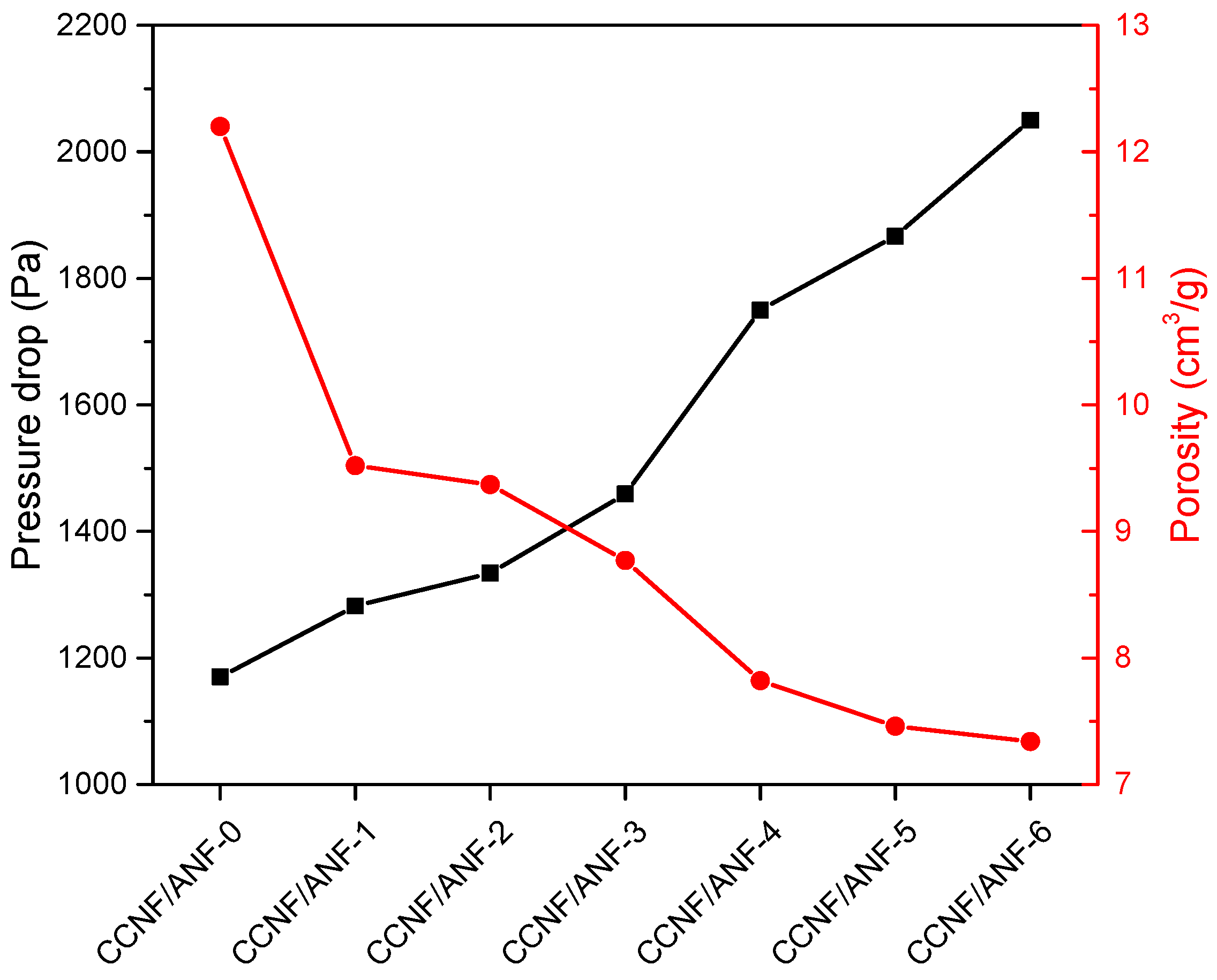
| Sample ID | Average Pressure Drop (Pa) | Standard Deviation (Pa) |
|---|---|---|
| CCNF/ANF-0 | 1170 | 30.50 |
| CCNF/ANF-1 | 1282 | 32.18 |
| CCNF/ANF-2 | 1334 | 21.37 |
| CCNF/ANF-3 | 1459 | 24.01 |
| CCNF/ANF-4 | 1750 | 31.81 |
| CCNF/ANF-5 | 1867 | 25.33 |
| CCNF/ANF-6 | 2050 | 27.84 |
| Sample ID | Porous Composite Weight M1 (g) | Apparent Density ρ1 (g/cm3) | Porosity P (cm3/g) |
|---|---|---|---|
| CCNF/ANF-0 | 0.266 | 0.079 | 12.2 |
| CCNF/ANF-1 | 0.337 | 0.100 | 9.52 |
| CCNF/ANF-2 | 0.342 | 0.101 | 9.37 |
| CCNF/ANF-3 | 0.364 | 0.107 | 8.77 |
| CCNF/ANF-4 | 0.406 | 0.12 | 7.82 |
| CCNF/ANF-5 | 0.424 | 0.125 | 7.46 |
| CCNF/ANF-6 | 0.43 | 0.127 | 7.34 |
Disclaimer/Publisher’s Note: The statements, opinions and data contained in all publications are solely those of the individual author(s) and contributor(s) and not of MDPI and/or the editor(s). MDPI and/or the editor(s) disclaim responsibility for any injury to people or property resulting from any ideas, methods, instructions or products referred to in the content. |
© 2023 by the authors. Licensee MDPI, Basel, Switzerland. This article is an open access article distributed under the terms and conditions of the Creative Commons Attribution (CC BY) license (https://creativecommons.org/licenses/by/4.0/).
Share and Cite
Yang, G.; Hou, N.; Li, Z.; Huang, K.; Zhang, B.; Xu, J.; Sun, J. Pressure Drop Performance of Porous Composites Based on Cotton Cellulose Nanofiber and Aramid Nanofiber for Cigarette Filter Rod. Materials 2023, 16, 411. https://doi.org/10.3390/ma16010411
Yang G, Hou N, Li Z, Huang K, Zhang B, Xu J, Sun J. Pressure Drop Performance of Porous Composites Based on Cotton Cellulose Nanofiber and Aramid Nanofiber for Cigarette Filter Rod. Materials. 2023; 16(1):411. https://doi.org/10.3390/ma16010411
Chicago/Turabian StyleYang, Guangyuan, Ning Hou, Zheming Li, Ke Huang, Bin Zhang, Jie Xu, and Jiuxiao Sun. 2023. "Pressure Drop Performance of Porous Composites Based on Cotton Cellulose Nanofiber and Aramid Nanofiber for Cigarette Filter Rod" Materials 16, no. 1: 411. https://doi.org/10.3390/ma16010411