Article

In Situ Reactive Formation of Mixed Oxides in Additively Manufactured Cobalt Alloy

1
School of Materials Engineering, Purdue University, West Lafayette, IN 47907, USA
2
Praxair Surface Technologies, Inc., Indianapolis, IN 46222, USA
3
School of Electrical and Computer Engineering, Purdue University, West Lafayette, IN 47907, USA
*
Author to whom correspondence should be addressed.
Materials 2023, 16(10), 3707; https://doi.org/10.3390/ma16103707
Submission received: 22 April 2023 / Revised: 5 May 2023 / Accepted: 10 May 2023 / Published: 13 May 2023
(This article belongs to the Special Issue Advances in Materials Processing Engineering)

Abstract

:
Oxide-dispersion-strengthened (ODS) alloys have long been considered for high temperature turbine, spacecraft, and nuclear reactor components due to their high temperature strength and radiation resistance. Conventional synthesis approaches of ODS alloys involve ball milling of powders and consolidation. In this work, a process-synergistic approach is used to introduce oxide particles during laser powder bed fusion (LPBF). Chromium (III) oxide (Cr2O3) powders are blended with a cobalt-based alloy, Mar-M 509, and exposed to laser irradiation, resulting in reduction–oxidation reactions involving metal (Ta, Ti, Zr) ions from the metal matrix to form mixed oxides of increased thermodynamic stability. A microstructure analysis indicates the formation of nanoscale spherical mixed oxide particles as well as large agglomerates with internal cracks. Chemical analyses confirm the presence of Ta, Ti, and Zr in agglomerated oxides, but primarily Zr in the nanoscale oxides. Mechanical testing reveals that agglomerate particle cracking is detrimental to tensile ductility compared to the base alloy, suggesting the need for improved processing methods to break up oxide particle clusters and promote their uniform dispersion during laser exposure.

1. Introduction

Laser powder bed fusion (LPBF) is a widely used metal additive manufacturing (AM) technology, which has advanced beyond rapid prototyping and into commercial part production. For high-value-added aerospace and medical industries, the resolution and part complexity achievable with LPBF can lead to improved performance [1]. In fact, the strength of LPBF AM components often exceeds their cast or wrought counterparts, owing to a refined microstructure formed during the rapid laser melting and the resolidification of metal powders [2]. A further improvement of material performance for high temperature components can be achieved by metal matrix composites (MMCs) reinforced with high temperature ceramic particles [3]. An important type of MMCs is the oxide-dispersion-strengthened (ODS) alloy. It is challenging to use AM techniques to fabricate ODS alloys, and it is important to investigate discrete powder particle mixtures to identify and assess the processing challenges.
ODS MMCs are desirable for nuclear applications for their resistance to radiation-induced void swelling and high strength at high temperatures [4,5]. Since oxide particles are hard enough to be considered nondeformable, the dislocation bowing theory indicates that their strengthening effect is maximized at smaller particle radii [6]. Oxide particles act as stable pinning sites, preventing grain growth at higher temperatures. Traditional approaches for producing an ODS material involve long-duration mechanical alloying combined with powder metallurgy consolidation methods such as spark plasma sintering and hot isostatic pressing [7,8,9]. Another process called gas-atomized reactive (GAR) atomization has been employed to form oxide particles within metal powder particles by the controlled introduction of oxygen into the argon gas atomization process [10,11,12,13]. Similarly, some studies have formed the oxide particles during LPBF by the addition of oxygen to the process atmosphere [14,15]. This work uses a straightforward approach of the mixture of oxide nanopowders with LPBF alloy powders prior to LPBF fabrication, which has been shown to be capable of forming nanoscale oxide reinforcement [16,17].
While powder metallurgy approaches can achieve small oxide sizes, these methods pose challenges for the fabrication of complex part geometries. Consolidation techniques generally require simple geometry even for pressure distribution, and the fine crystallites produced in mechanical alloying make the deformation processing of complex shapes arduous. In contrast, LPBF can produce parts with complex geometric features, which do not add to the processing cost [18]. Additionally, the local laser melting of the tracks of powder material can also promote oxide-particle-size refinement and distribution [19]. In conjunction, oxide particles in the melt pool can act as nucleation sites, refining grain size and reducing grain texture anisotropy. Multiple groups have studied the use of LPBF as a fabrication method for particle-reinforced MMCs. In some cases, an oxygen-containing atmosphere is used for in situ oxide synthesis in the melt pool [19]. Directed energy deposition (DED), a laser-based powder-fed process with large melt pools has also been used [20]. Typical reinforcement particles include SiC, TiC, Y2O3, and Al2O3 [17,21,22,23,24] in matrix alloys such as Al, ferritic or austenitic steels, or Ni alloys [14]. In ODS with titanium-containing matrix alloys, a complex Y2Ti2O7 oxide is formed [25]. Similarly, multiple groups have shown that the addition of elemental hafnium results in the formation of a Y2Hf2O7 complex oxide accompanied with a decrease in oxide particle size from 50 nm to 10 nm [26,27].
To date, there is little study on Co-based ODS alloys. The Mar-M 509 cobalt alloy was introduced in 1965 by Lockheed Martin as an elevated temperature cast alloy strengthened with carbides for blading applications [28,29,30]. Cobalt has a higher melting temperature and higher thermal conductivity than Nickel, enabling higher operating temperatures in actively cooled components [31]. Co-base alloys such as Mar-M 509 also possess improved sulfidation resistance [32]. While in many of the hot sections of engines, where blades have been replaced with Ni-base superalloys due to the improved creep resistance mechanisms in γ/γ′ microstructures, there remains a need for carbide- and solid solution-strengthened Co alloys for stationary components such as nozzle guide vanes [33]. These components encounter high temperature exposure for long periods and applied loads are low enough that thermomechanical fatigue and surface oxidation become a more important concern [34]. Solid solution strengthening contributions arise from the matrix substitution of W, Ta, and Cr [35]. Carbides are desirable precipitates that improve tensile and creep strength and they have better thermal stability than γ′ precipitates, [36,37,38,39]. In cast Mar-M 509, Cr contributes to the formation of M23C6 carbides at room and intermediate temperatures and M7C3 carbides at higher temperatures during solidification [29,40]. Mixed MC carbides enriched in Ta, W, Ti, and Zr are stable across all temperatures and form in the mushy zone during solidification [40,41]. However, the exact carbide phases present from nonequilibrium solidification in LPBF Mar-M 509 are not well characterized.
In this work, 1.5 weight percent Cr2O3 powders were incorporated into Mar-M 509 Co alloy powders and processed into ODS composite material by LPBF. The resulting microstructures contained a combination of 10–100 nm oxide nanoparticles within cellular solidification structures and 10–50 µm oxide agglomerates, which are extensively characterized by microscopy. Both morphologies of oxide transformed into a mixed Ta-, Ti-, Zr-rich oxide phase by a hypothesized reduction–oxidation reaction. Tension testing and fracture surface investigation indicated that the larger agglomerated oxide particles are responsible for greatly reduced tensile strain. Both the nanoscale oxides and micron-scale agglomerates suggest that improvements in processing can lead to success in the fabrication of homogenous ODS alloys by LPBF.

2. Materials and Methods

LPBF specimens were produced using commercial Mar-M 509 argon gas-atomized powder sourced from Praxair Surface Technologies, Inc. (PST), Indianapolis, IN, USA. Scanning electron microscopy (SEM) images of the as-received powders are given in Figure 1a,b. The powder particle size was measured by MICROTRAC analysis, providing results of d10, d50, d90 (10th, 50th, 90th diameter percentile) of 22.2, 30.4, and 43.6 µm, respectively. The Mar-M 509 alloy powder chemistry as measured by inductively coupled plasma mass spectrometry is provided in Table 1. Cr2O3 powder provided by PST had MICROTRAC d10, d50, d90 of 1.59, 3.22, and 9.97 µm, respectively. ODS powders and Co alloy powders were mixed in a commercial V blender until uniform and stored in containers filled with argon gas until use in additive manufacturing. SEM micrographs in Figure 1 indicate that the Cr2O3 powder exists as surface-bonded and isolated forms, as indicated by Figure 1d and the energy dispersive spectroscopy (EDS) map in Figure 1e,f.
Both virgin and ODS Mar-M 509 powders were fabricated using an EOS M290 LPBF device on 316L stainless steel build plate held at 80 °C using baseline parameters of 285 W laser power, 960 mm/s laser scan speed, 110 µm hatch spacing, and 40 µm nominal layer thickness. Using Equation (1), the volumetric energy density (VED), ψ, can be calculated, which is a useful index for comparing relative heat input of combinations of parameter sets. P is the laser power in W, v is the laser scan speed in mm/s, d is the layer thickness in mm, resulting in ψ units of J/mm3.
ψ = P v h d
Laser power and scan speed were increased/decreased by 15% in conjunction with probe higher and lower energy inputs. The parameter sets and respective energy densities are given in Table 2. Sample geometries fabricated consisted of cubes with 1 cm3 volume for microstructure analysis and 40 × 8 × 1.5 mm flat coupons for tensile dogbone production, oriented with the 1.5 × 40 mm face bonded to the build plate. The LPBF scan strategy utilized a contour–infill approach where the infill is a simple raster across the part profile. The raster direction was rotated by 67° for each successive layer to prevent the alignment of laser track boundaries.
Fabricated samples were removed from the 316 stainless-steel build plate by wire electrical discharge machining. Tensile dogbones were laser-cut and polished to 800 grit SiC paper to reduce the impact of surface defects on tension results. Tension testing was performed using an MTS Insight 100 Universal Test System equipped with a 30 kN load cell and a strain rate of 10−3. Strain was measured using an extensometer.
X-ray diffraction was performed on the XY and YZ polished planes using a Bruker (Billerica, MA, USA) D8 Focus with Cu Kα radiation (λ = 1.54 Å) over the 2θ range from 30° to 100°. SEM and electron dispersive spectroscopy (EDS) were performed using FEI (Hillsboro, OH, USA) Quanta 650 Field Emission Gun (FEG) and FEI Quanta 3D FEG microscopes using 20 kV accelerating voltage.
Samples for transmission electron microscopy (TEM) were prepared by mechanically grinding foils to ~70 µm in thickness before using the twin-jet polishing method to form an electron-transparent region surrounding the electropolished perforation in the 3 mm punched disc. Twin-jet polishing was performed with a Fischione (Export, PA, USA) Model 110 electropolisher using a 5% perchloric acid solution in ethanol cooled to −30 °C at the beginning of polishing. A 27 V potential was applied, resulting in a current of 16 mA through the disc sample. TEM and EDS experiments were performed using an FEI Talos 200X transmission electron microscope operated at 200 kV.

3. Results

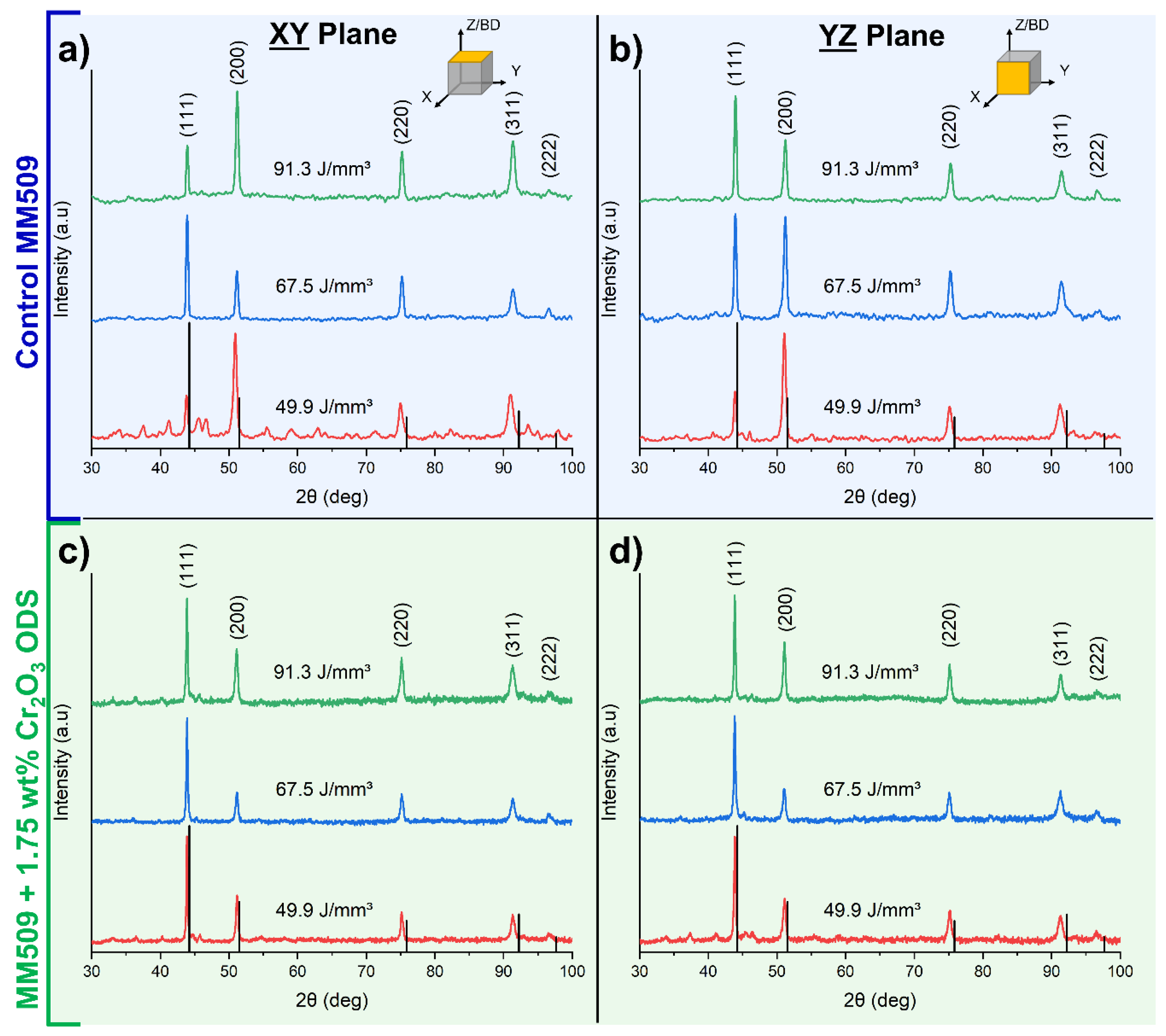
3.1. X-ray Diffraction and Texture Analysis

The X-ray diffraction spectra for control and ODS materials in the XY and YZ planes can be seen in Figure 2. As has been previously observed in laser additive-manufactured microstructures with face-centered cubic (FCC) matrix crystal structures, there is preferential orientation along the (200) direction of the XY plane of control samples (Figure 2d) [42]. This is the preferred growth direction in FCC crystals during directional solidification due to thermal gradients [43]. The dominant peak in the ODS samples shifts to the (111) peak. Peak shift toward the lower 2θ compared to the reference peaks indicates a larger interplanar spacing in the Mar-M 509 alloy. This effect can be explained by the presence of solid solution elements in the matrix such as Cr, Ta, and W, which have larger atomic radii than the Co, increasing the interplanar spacing. Low intensity carbide peaks are visible in some samples, but the fluorescence phenomenon of cobalt under Cu Kα radiation causes high background intensity, making the reliable deconvolution of low intensity peaks from the background challenging.

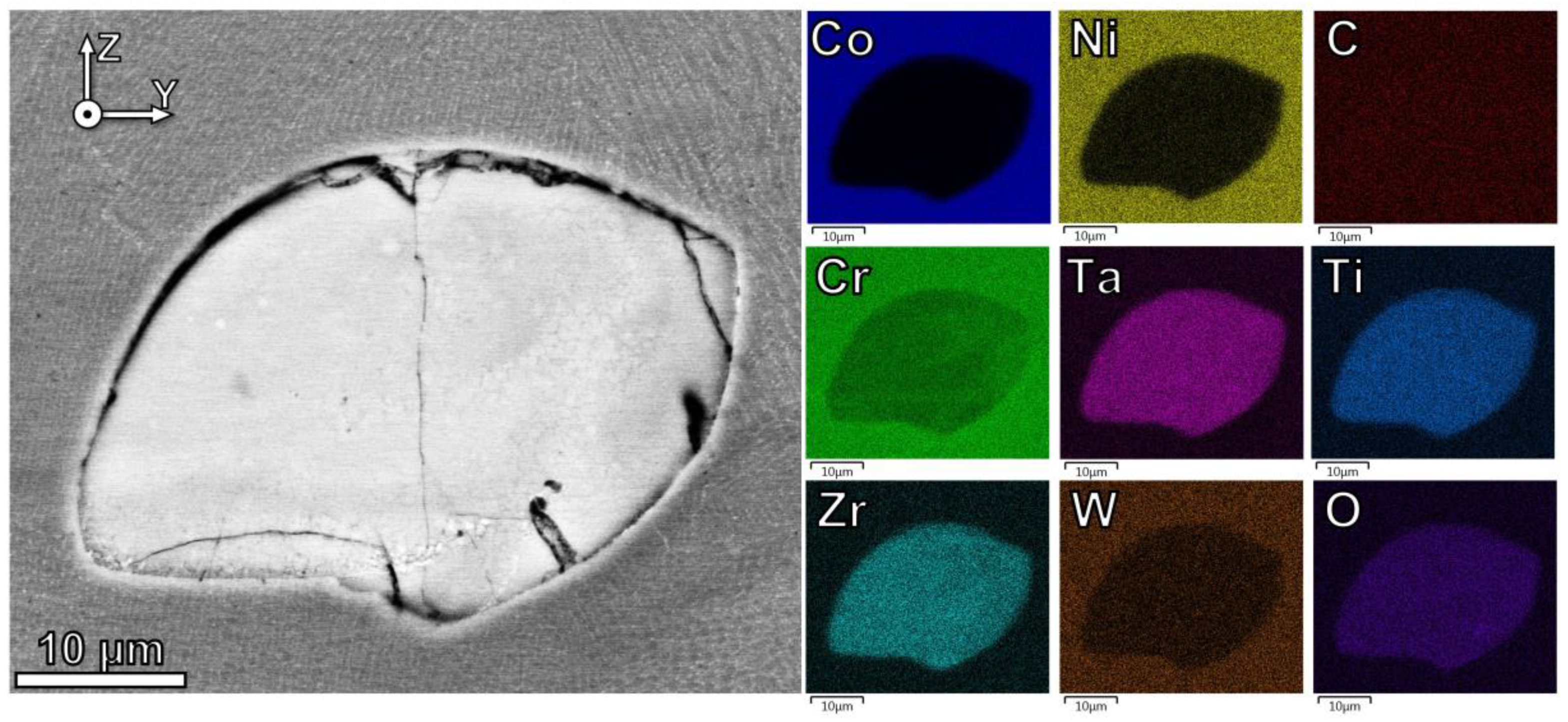
3.2. Microstructure Analysis

SEM micrographs show that the microstructure of control alloy consists of a cellular-dendritic structure as shown in Figure 3a,b. Cellular structures primarily exist at the boundaries of the melt pool, where the thermal gradient is largest during the first stage of melt pool solidification [44]. The thermal gradient has a vector component toward the center of the melt pool where much of the thermal mass is contained, but also a vector component oriented along the build direction, since the cooling rate of the solid conduction outweighs conductive and convective cooling at the free surface of the melt pool [45]. As the thermal gradient decreases while moving toward the melt pool center, there is a shift to dendritic structures [46]. There are many occurrences of epitaxial growth across the melt pool boundaries, with new grains adopting the orientation of the crystals at the boundary. Figure 3b contains a change in the dendrite growth direction from [001] to [010], which is along the thermal gradient direction toward the melt pool center; after the crystals propagated for 5–10 µm, they then shifted back to [001] growth direction. Due to the complex heat flow caused by laser scan overlap, raster direction rotation, and layer remelting, the localized thermal gradient is spatially varied with respect to the examination plane.
The microstructures of Cr2O3 oxide dispersion alloys manufactured using VED of 67.5 J/mm3 are shown in SEM micrographs in Figure 3c,d (the YZ plane) and in Figure 3e,f (the XY plane). It can be seen in Figure 3c that some agglomerated nanoscale oxide powders which existed along the melt pool boundaries presumably drifted during AM by buoyancy and Marangoni convection forces [47]. This phenomenon was observed in many locations in this viewing plane. The agglomerates are on the order of 50 µm in size and contain internal cracks due to thermal contraction stresses from the metal matrix during post-solidification cooling, as reported previously in other LPBF oxide-modified powders [26]. The XY plane view in Figure 3e indicates that these internal oxide cracks can easily propagate into the matrix, leading to widespread cracking in the fabricated oxide dispersion samples. Figure 3f displays delamination of the oxide–matrix interface as well as intercellular/interdendritic fracture in the vicinity of the oxide particle. The presence of the oxide particle and thermal contraction of the matrix results in a stress field surrounding the oxide particle, which is sufficient to initiate fracture in the matrix along the weaker direction, transverse to the directional solidification cells/dendrites.
An intriguing phenomenon that is identified is the reaction of the initial Cr2O3 oxide into a mixed oxide containing Ta, Ti, and Zr, which are present in the alloy matrix. The enrichment of these elements and the depletion of Cr in oxide clusters is detected by the EDS map in Figure 4. The respective oxides for Ta, Ti, and Zr each have a higher thermodynamic stability/lower Gibbs free energy of formation than the Cr2O3, implying a net energy gain for these reactions [48]. The reduction–oxidation (redox) reactions governing this change are discussed in Section 4.1.
A TEM micrograph in Figure 5a reveals a second prevalent morphology of oxide particle with a size of 10–100 nm within the matrix. Additional TEM micrographs are available in Appendix A. Stacking faults were observed near oxide particles, where interfacial stresses are at a maximum. Figure 5b shows 80 nm oxide particles with hexagonal morphology sharing an interface with the intercellular carbide precipitates. STEM micrograph and EDS maps in Figure 5c identifies these oxide nanoparticles to be enriched in Zr. Isolated Zr oxides are located within cells but also coincide with some of the MC carbides in the intercellular region.

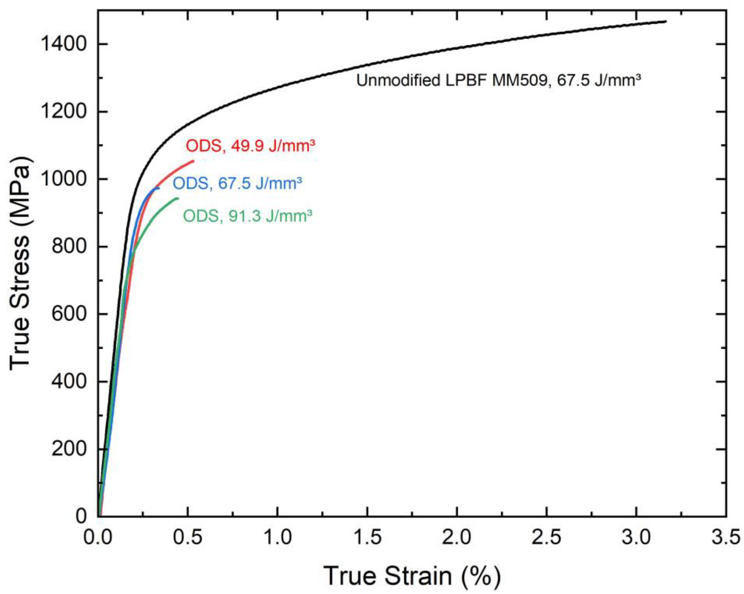
3.3. Mechanical Properties

The plots of room temperature true stress–true strain curves are presented in Figure 6. Regardless of LPBF parameters used in the oxide-modified Mar-M 509, a clear decrease in strength and ductility is observed compared to the control LPBF samples. The calculated yield strength, ultimate tensile strength, and elongation at fracture for each of these curves are given in Table 3. Neither materials exhibited necking behavior prior to fracture.
The fracture surfaces imaged by SEM in Figure 7 inform the cause of reduced strength and ductility in the oxide dispersion materials. Most of the oxide-modified fracture surface consists of brittle intercellular or interdendritic fracture morphology, wherein cracks propagate along the region between the respective directional solidification structures. Cellular regions which coincide with the melt pool boundaries can be distinguished, as shown in Figure 7a. A higher magnification of the interdendritic fracture surface morphology is shown in Figure 7c, with bright nanoscale MC carbides decorating the interdendritic surfaces.
Unlike the control Mar-M509 material, the fracture surfaces of the oxide-modified LPBF material additionally contain 50–100 μm oxide agglomerates, which are internally cracked, and their surfaces are delaminated from the matrix, as can be observed in Figure 7b. In the higher magnification image in Figure 7d, a crack originating at the agglomerate–matrix interface can be observed, propagating into the surrounding matrix.

4. Discussion

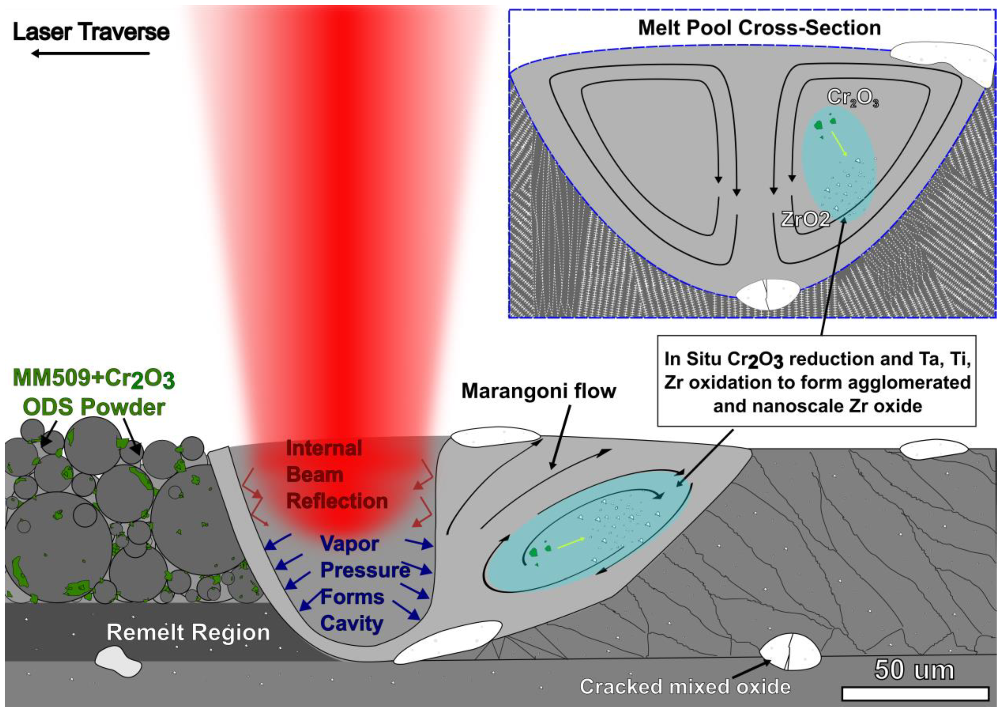
4.1. In Situ Reduction–Oxidation Reactions in LPBF ODS Mar-M 509

The crystal structure of the mixed oxide phase in this work is unconfirmed, and it appears that the large, agglomerated oxides and nanoscale oxides have differing compositions. The fact that the large oxide agglomerates contain Ta, Ti, and Zr and the nanoscale oxides contain primarily Zr suggests that the respective free energies and diffusion distances achievable during LPBF impact the formation mechanism. We have recently reported on a similar Cr2O3 oxide transformation phenomenon in LPBF Inconel 718 Ni alloy in which the Cr2O3 undergoes a reduction–oxidation reaction during laser exposure, resulting in the formation of a higher stability of Al2O3 and TiO2 nanoparticles, and these reactions were shown to be exothermic for either pure oxide [49]. Other works utilizing Y2O3 as the initial oxide in in situ ODS manufacturing have reported the formation of a Y–Al–O oxide, even though the Gibbs free energy of formation at 1480 K for Y2O3 is lower (−988.5 KJ/mol) than for Al2O3 (−802.2 KJ/mol), suggesting that the mixed oxide form has an even lower Gibbs free energy of formation than either pure compound [14,48]. Zhang et al. observed the decomposition of Y2O3 in Co–15Y2O3 ball-smilled mixtures with increasing milling time and argued that the increase in interfacial energy provides a driving force for decomposition into unstable Y and O, which formed stable Hf, Ti, Zr, and Ca mixed oxides with varying degrees of particle size refinement [27].
Backman and Opila assessed the formation energy and oxygen diffusivity of group IV, V, and VI transition metal oxides and carbides [50]. They found that the group IV elements (Ti and Zr in Mar-M 509) have the most stable oxides with the highest melting temperatures, followed by group V (Ta in Mar-M 509), and lastly, group VI (W in Mar-M 509). Additionally, the oxygen diffusivity was found to be high in zirconia (ZrO2), which has the highest melting temperature of the investigated oxides, indicating ZrO2 can readily form in the presence of oxygen in the melt pool [50]. These thermodynamic values agree with the observations in this work. It is hypothesized the small 10–100 nm oxide nanoparticles in the presence of ODS Mar-M509 have shorter solidification times and therefore less diffusion, favoring the formation of ZrO2. In larger agglomerated particles, there is a higher oxygen concentration and a longer solidification time, so Ti and Ta can diffuse into the oxide, as observed in Figure 4. Tungsten oxides have higher Gibbs free energy of formation and relatively lower solidification temperatures, so Tungsten is not found in the agglomerates or nanoscale oxides. The kinetics of formation of mixed oxides are not well understood, and fundamental research in this area would assist in explaining the size-dependent composition of the oxides found in this material.

4.2. Oxide Particle Impact on Microstructure

A schematic for the proposed mechanism for the evolution of oxide size and positioning within the fluid melt pool is provided in Figure 8. During AM, a melt pool forms. The vaporization of metals creates pressure that maintains a vapor cavity just below the laser spot as the melt pool moves along the track line [51]. As the vaporized metal is expelled upwards from the cavity, gas flows into the resulting lateral low-pressure areas and powder particles are entrained in the gas flow and fall into the melt pool, creating a so-called “denudation zone” [52,53]. Marangoni convective flow within the liquid metal pool distributes nanoscale oxide powders, which solidify above the metal alloy liquidus temperature [51]. Buoyancy forces on the lower-density oxides in combination with circular convection currents causes the pushing of large oxide agglomerates to the melt pool boundaries, both to the surface and the solid–liquid interface, where they are trapped [47,54]. The same distribution of agglomerated oxides at melt pool boundaries has been observed in our single-layer exposure experiments (not shown here) with well-defined boundaries, compared to bulk samples in which some material is remelted multiple times. X-ray diffraction showing reduced crystallographic texture may suggest that the presence of oxide particles provides additional nucleation sites, which result in more equiaxed grain structure [55].
From the TEM micrograph in Figure 5, it is evident that oxides in the 10–100 nm range also exist within the microstructure. The exact formation mechanism of these smaller particles is unconfirmed, although due to their high melting temperature, the oxide particles solidify before the Co matrix. It is hypothesized that either the turbulent Marangoni flow, the reduction–oxidation reaction, or some combination of these effects is responsible for the formation of nanoscale oxides. The interdendritic/intercellular continuous carbide chains appear to nucleate heterogeneously on the oxide particle surfaces, as seen in Figure 5b. Mao et al. found a semi-coherent relationship between Y2Ti2O7 and an austenitic steel matrix, specifically ( 2 ¯ 20 ) Y 2 T i 2 O 7 | | ( 200 ) M a t r i x and ( 3 ¯ 3 ¯ 1 ) Y 2 T i 2 O 7 | | ( 0 2 ¯ 2 ) M a t r i x orientation relationships [56]. Another possible mechanism is the formation of zirconium oxide using the MC carbides as a source of zirconium, since ZrO has a lower Gibbs free energy and the oxidation rate of ZrC is 2× higher than TaC and over 10× higher than TiC [50,57].

4.3. Oxide Particle Impact on Mechanical Properties

Due to the limited strain tolerance of the directionally solidified matrix–carbide structures found in LPBF Mar-M 509, the stress fields around the large oxide agglomerates cannot be accommodated with plasticity, leading to cracking. The formation of Zr-rich oxide nanoparticles suggests the potential to achieve a stable, Orowan-strengthened ODS microstructure. The stress fields generated by the nanoscale oxides are less impactful and are shown to be accommodated by the generation of stacking faults near the oxide/matrix interface, as can be seen in Figure 5. In an idealized microstructure without large agglomerates and cracks, nanoscale oxide-particle-induced planar defect generation may further inhibit dislocation motion, providing additional strength.

5. Conclusions

This work investigated the formation and dispersion of oxides through the LPBF of Mar-M 509 and Cr2O3 powders. The following conclusions are made:
  • A reduction–oxidation transformation from Cr2O3 to a more stable mixed tantalum, titanium, and zirconium oxide is observed. These reactions could be used to achieve higher entropy mixed oxide compositions in situ.
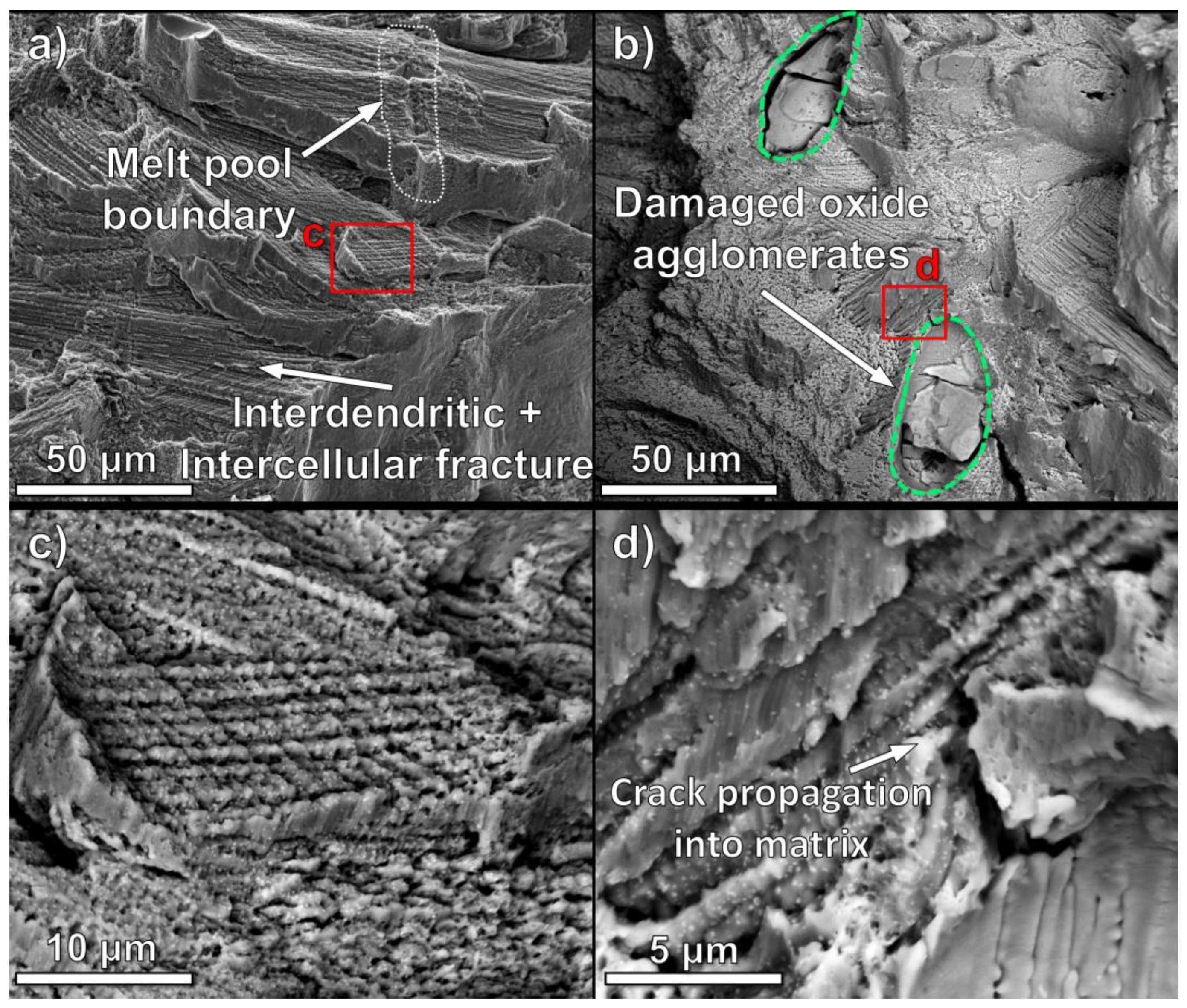
  • The macroscale brittle behavior of oxide dispersion of Mar-M 509 is caused by cracking near the 50–100 µm agglomerated oxide particles. Residual stress-induced cracks in the oxide particles propagate into the matrix and rapidly grow along the aligned carbide precipitates in the as-printed Mar-M 509.
  • Zirconium-rich nanoscale oxides in the matrix provide potential for an idealized oxide-dispersion-strengthened system for high temperature applications due to the high thermal stability of the oxide particles.

Author Contributions

Conceptualization, J.L., R.C., D.H., D.M. and Q.S.; methodology, J.L., R.C., D.H., D.M. and Q.S.; investigation, J.L., B.Y., R.C., D.H., D.M. and Q.S.; resources, X.Z., W.J. and J.C.; formal analysis, J.L.; writing—original draft preparation, J.L.; writing—review and editing, J.L. and X.Z.; visualization, J.L.; supervision, J.C., W.J. and X.Z.; project administration, J.C., J.L., W.J., H.W. and X.Z.; funding acquisition, J.C., W.J., H.W. and X.Z. All authors have read and agreed to the published version of the manuscript.

Funding

J.L. is supported by NSF AGEP fellowship under DMR-2016453. X.Z. acknowledges support by NSF-DFG CMMI grant number 2228266. B.Y. and H.W. acknowledge financial support for TEM studies by the U.S. Office of Naval Research N00014-17-1-2087 and N00014-20-1-2043.

Institutional Review Board Statement

Not applicable.

Informed Consent Statement

Not applicable.

Data Availability Statement

Not applicable.

Acknowledgments

The authors would like to thank the Purdue Electron Microscopy facility for equipment support and training. Additionally, the authors would like to thank the Purdue School of Materials Engineering lab equipment managers.

Conflicts of Interest

William Jarosinski and Joseph Corpus declare their employment by and shareholding in Praxair Surface Technologies, Inc.; a Linde company, through company sponsored savings and retirement plans. Praxair Surface Technologies is a manufacturer of metal powders for additive manufacturing, representing potential conflict of interest.

Appendix A

Figure A1. HAADF STEM micrograph and EDS maps of a cellular region, with the cell elongation direction out of plane and a hexagonal cross-section. Carbide and oxide precipitates exist in the intercellular boundaries and some Zr oxide is located within the cells.
Materials 16 03707 g0a1

References

  1. Gibson, I.; Rosen, D.; Stucker, B.; Khorasani, M. Additive Manufacturing Technologies; Springer International Publishing: Cham, Switzerland, 2021; Volume 89, ISBN 978-3-030-56126-0. [Google Scholar]
  2. Ghiaasiaan, R.; Muhammad, M.; Gradl, P.R.; Shao, S.; Shamsaei, N. Superior Tensile Properties of Hastelloy X Enabled by Additive Manufacturing. Mater. Res. Lett. 2021, 9, 308–314. [Google Scholar] [CrossRef]
  3. Singh, K. Advanced Materials for Land Based Gas Turbines. Trans. Indian Inst. Met. 2014, 67, 601–615. [Google Scholar] [CrossRef]
  4. Oono, N.; Ukai, S.; Kondo, S.; Hashitomi, O.; Kimura, A. Irradiation Effects in Oxide Dispersion Strengthened (ODS) Ni-Base Alloys for Gen. IV Nuclear Reactors. J. Nucl. Mater. 2015, 465, 835–839. [Google Scholar] [CrossRef]
  5. Raman, L.; Gothandapani, K.; Murty, B.S. Austenitic Oxide Dispersion Strengthened Steels: A Review. Def. Sci. J. 2016, 66, 316–322. [Google Scholar] [CrossRef]
  6. Courtney, T.H. Mechanical Behavior of Materials, 2nd ed.; Waveland Press: Long Grove, IL, USA, 2005; ISBN 978-1-57766-425-3. [Google Scholar]
  7. Amirjan, M. Development of Ni-Base Oxide Dispersion Strengthened Alloys Using Yttria-Stabilised Zirconia Nanoparticles: Powder Preparation and Spark Plasma Sintering Processing. Powder Metall. 2022, 65, 222–234. [Google Scholar] [CrossRef]
  8. Pasebani, S.; Dutt, A.K.; Burns, J.; Charit, I.; Mishra, R.S. Oxide Dispersion Strengthened Nickel Based Alloys via Spark Plasma Sintering. Mater. Sci. Eng. A 2015, 630, 155–169. [Google Scholar] [CrossRef]
  9. Ghasali, E.; Fazili, A.; Alizadeh, M.; Shirvanimoghaddam, K.; Ebadzadeh, T. Evaluation of Microstructure and Mechanical Properties of Al-TiC Metal Matrix Composite Prepared by Conventional, Microwave and Spark Plasma Sintering Methods. Materials 2017, 10, 1255. [Google Scholar] [CrossRef]
  10. Rieken, J.R. Gas Atomized Precursor Alloy Powder for Oxide Dispersion Strengthened Ferritic Stainless Steel. Ph.D. Thesis, Iowa State University, Ames, IA, USA, 2011. [Google Scholar]
  11. Horn, T.; Rock, C.; Kaoumi, D.; Anderson, I.; White, E.; Prost, T.; Rieken, J.; Saptarshi, S.; Schoell, R.; DeJong, M.; et al. Laser Powder Bed Fusion Additive Manufacturing of Oxide Dispersion Strengthened Steel Using Gas Atomized Reaction Synthesis Powder. Mater. Des. 2022, 216, 110574. [Google Scholar] [CrossRef]
  12. Zhang, D.; Darsell, J.T.; Wang, J.; Ma, X.; Grant, G.J.; Anderson, I.E.; Rieken, J.R.; Edwards, D.J.; Setyawan, W.; Horn, T.J.; et al. No Ball Milling Needed: Alternative ODS Steel Manufacturing with Gas Atomization Reaction Synthesis (GARS) and Friction-Based Processing. J. Nucl. Mater. 2022, 566, 153768. [Google Scholar] [CrossRef]
  13. Bergner, F.; Hilger, I.; Virta, J.; Lagerbom, J.; Gerbeth, G.; Connolly, S.; Hong, Z.; Grant, P.S.; Weissgärber, T. Alternative Fabrication Routes toward Oxide-Dispersion-Strengthened Steels and Model Alloys. Metall. Mater. Trans. A 2016, 47, 5313–5324. [Google Scholar] [CrossRef]
  14. Mirzababaei, S.; Ghayoor, M.; Doyle, R.P.; Pasebani, S. In-Situ Manufacturing of ODS FeCrAlY Alloy via Laser Powder Bed Fusion. Mater. Lett. 2021, 284, 129046. [Google Scholar] [CrossRef]
  15. Chen, P.; Yang, C.; Li, S.; Attallah, M.M.; Yan, M. In-Situ Alloyed, Oxide-Dispersion-Strengthened CoCrFeMnNi High Entropy Alloy Fabricated via Laser Powder Bed Fusion. Mater. Des. 2020, 194, 108966. [Google Scholar] [CrossRef]
  16. Xu, R.; Geng, Z.; Wu, Y.; Chen, C.; Ni, M.; Li, D.; Zhang, T.; Huang, H.; Liu, F.; Li, R.; et al. Microstructure and Mechanical Properties of In-Situ Oxide-Dispersion-Strengthened NiCrFeY Alloy Produced by Laser Powder Bed Fusion. Adv. Powder Mater. 2022, 1, 100056. [Google Scholar] [CrossRef]
  17. Smith, T.M.; Thompson, A.C.; Gabb, T.P.; Bowman, C.L.; Kantzos, C.A. Efficient Production of a High-Performance Dispersion Strengthened, Multi-Principal Element Alloy. Sci. Rep. 2020, 10, 9663. [Google Scholar] [CrossRef]
  18. Ashby, M.F. Materials Selection in Mechanical Design, 4th ed.; Butterworth-Heinemann: Burlington, MA, USA, 2011; ISBN 978-1-85617-663-7. [Google Scholar]
  19. Haines, M.P.; Peter, N.J.; Babu, S.S.; Jägle, E.A. In-Situ Synthesis of Oxides by Reactive Process Atmospheres during L-PBF of Stainless Steel. Addit. Manuf. 2020, 33, 101178. [Google Scholar] [CrossRef]
  20. Chia, E.; Kang, B.; Zheng, M.; Li, Y.; Chyu, M. Development of Ods Coating for High Temperature Turbine Components Using Ded Additive Manufacturing. In Proceedings of the ASME Turbo Expo 2018: Turbomachinery Technical Conference and Exposition, Oslo, Norway, 11 June 2018. [Google Scholar]
  21. Bhowmik, A.; Zhai, W.; Zhou, W.; Nai, S.M.L. Characterization of Carbide Particle-Reinforced 316L Stainless Steel Fabricated by Selective Laser Melting. Mater. Charact. 2021, 179, 111360. [Google Scholar] [CrossRef]
  22. Li, J.; Qu, H.; Bai, J. Grain Boundary Engineering during the Laser Powder Bed Fusion of TiC/316L Stainless Steel Composites: New Mechanism for Forming TiC-Induced Special Grain Boundaries. Acta Mater. 2022, 226, 117605. [Google Scholar] [CrossRef]
  23. Lin, T.C.; Cao, C.; Sokoluk, M.; Jiang, L.; Wang, X.; Schoenung, J.M.; Lavernia, E.J.; Li, X. Aluminum with Dispersed Nanoparticles by Laser Additive Manufacturing. Nat. Commun. 2019, 10, 4124. [Google Scholar] [CrossRef] [PubMed]
  24. Chen, B.; Xi, X.; Tan, C.; Song, X. Recent Progress in Laser Additive Manufacturing of Aluminum Matrix Composites. Curr. Opin. Chem. Eng. 2020, 28, 28–35. [Google Scholar] [CrossRef]
  25. Arora, A.; Mula, S. Effect of Ti Addition on Thermal Stability and Phase Evolution of Super-Invar Based Yttria Added ODS Alloys Developed by Mechanical Alloying and Spark Plasma Sintering. J. Alloys Compd. 2022, 899, 163336. [Google Scholar] [CrossRef]
  26. Ghayoor, M.; Lee, K.; He, Y.; Chang, C.; Paul, B.K.; Pasebani, S. Selective Laser Melting of Austenitic Oxide Dispersion Strengthened Steel: Processing, Microstructural Evolution and Strengthening Mechanisms. Mater. Sci. Eng. A 2020, 788, 139532. [Google Scholar] [CrossRef]
  27. Zhang, L.; Ukai, S.; Hoshino, T.; Hayashi, S.; Qu, X. Y2O3 Evolution and Dispersion Refinement in Co-Base ODS Alloys. Acta Mater. 2009, 57, 3671–3682. [Google Scholar] [CrossRef]
  28. Wheaton, H.L. MAR-M 509, A New Cast Cobalt-Base Alloy for High-Temperature Service. Cobalt 1965, 29, 163–170. [Google Scholar]
  29. Woulds, M.J. Recent Developments in Mar M 509. Cobalt 1969, 42, 3–13. [Google Scholar]
  30. Sims, C. Contemporary View of Cobalt-Base Alloys. J. Met. 1969, 21, 27–42. [Google Scholar] [CrossRef]
  31. Davis, J.R. Cobalt and Cobalt Alloys. In Metals Handbook Desk Edition; ASM International: Almere, The Netherlands, 1998; pp. 616–620. [Google Scholar]
  32. Morral, F.R. Cobalt-Base Alloys in Aerospace. Space Congr. Proc. 1970, 1970, 53–64. [Google Scholar]
  33. Krewinkel, R.; Such, A.; de la Torre, A.O.; Wiedermann, A.; Castillo, D.; Rodriguez, S.A.; Schleifenbaum, J.H.; Blaswich, M. Design and Characterization of Additively Manufactured NGVs Operated in a Small Industrial Gas Turbine. Int. J. Gas Turbine Propuls. Power Syst. 2020, 11, 36–44. [Google Scholar] [CrossRef] [PubMed]
  34. Reed, R.C. The Superalloys; Cambridge University Press: Cambridge, UK, 2006; ISBN 978-0-521-85904-2. [Google Scholar]
  35. Klarstrom, D.L. Heat Treatment of Cobalt-Base Alloys. In Heat Treating of Nonferrous Alloys; ASM International: Almere, The Netherlands, 2018; Volume 4, pp. 625–633. [Google Scholar] [CrossRef]
  36. Sato, J.; Omori, T.; Oikawa, K.; Ohnuma, I.; Kainuma, R.; Ishida, K. Cobalt-Base High-Temperature Alloys. Science 2006, 312, 90–91. [Google Scholar] [CrossRef]
  37. Pollock, T.M.; Dibbern, J.; Tsunekane, M.; Zhu, J.; Suzuki, A. New Co-Based γ-Γ′ High-Temperature Alloys. JOM 2010, 62, 58–63. [Google Scholar] [CrossRef]
  38. Pollock, T.M.; Clarke, A.J.; Babu, S.S. Design and Tailoring of Alloys for Additive Manufacturing. Metall. Mater. Trans. A Phys. Metall. Mater. Sci. 2020, 51, 6000–6019. [Google Scholar] [CrossRef]
  39. Suzuki, A.; Inui, H.; Pollock, T.M. L12-Strengthened Cobalt-Base Superalloys. Annu. Rev. Mater. Res. 2015, 45, 345–368. [Google Scholar] [CrossRef]
  40. Cacciamani, G.; Roncallo, G.; Wang, Y.; Vacchieri, E.; Costa, A. Thermodynamic Modelling of a Six Component (C-Co-Cr-Ni-Ta-W) System for the Simulation of Cobalt Based Alloys. J. Alloys Compd. 2018, 730, 291–310. [Google Scholar] [CrossRef]
  41. Opiekun, Z.; Chrusciel, K. Structural Studies of Partial Meltings of Casting Surfaces Made of Cobalt Alloy. Arch. Foundry Eng. 2009, 9, 197–200. [Google Scholar]
  42. Ferreri, N.C.; Ghorbanpour, S.; Bhowmik, S.; Lussier, R.; Bicknell, J.; Patterson, B.M.; Knezevic, M. Effects of Build Orientation and Heat Treatment on the Evolution of Microstructure and Mechanical Properties of Alloy Mar-M-509 Fabricated via Laser Powder Bed Fusion. Int. J. Plast. 2019, 121, 116–133. [Google Scholar] [CrossRef]
  43. Wang, W.; Lee, P.D.; McLean, M. A Model of Solidification Microstructures in Nickel-Based Superalloys: Predicting Primary Dendrite Spacing Selection. Acta Mater. 2003, 51, 2971–2987. [Google Scholar] [CrossRef]
  44. Yuan, L.; Sabau, A.S.; StJohn, D.; Prasad, A.; Lee, P.D. Columnar-to-Equiaxed Transition in a Laser Scan for Metal Additive Manufacturing. IOP Conf. Ser. Mater. Sci. Eng. 2020, 861, 012007. [Google Scholar] [CrossRef]
  45. Paul, S.; Liu, J.; Strayer, S.T.; Zhao, Y.; Sridar, S.; Klecka, M.A.; Xiong, W.; To, A.C. A Discrete Dendrite Dynamics Model for Epitaxial Columnar Grain Growth in Metal Additive Manufacturing with Application to Inconel. Addit. Manuf. 2020, 36, 101611. [Google Scholar] [CrossRef]
  46. Quested, P.N.; McLean, M. Solidification Morphologies in Directionally Solidified Superalloys. Mater. Sci. Eng. 1984, 65, 171–180. [Google Scholar] [CrossRef]
  47. Yang, Y.; Doñate-Buendía, C.; Oyedeji, T.D.; Gökce, B.; Xu, B.X. Nanoparticle Tracing during Laser Powder Bed Fusion of Oxide Dispersion Strengthened Steels. Materials 2021, 14, 3463. [Google Scholar] [CrossRef] [PubMed]
  48. Ellingham, H.J.T. Reducibility of Oxides and Sulphides in Metallurgical Processes. J. Soc. Chem. Ind. 1944, 63, 125–160. [Google Scholar] [CrossRef]
  49. Stegman, B.; Yang, B.; Shang, Z.; Ding, J.; Sun, T.; Lopez, J.; Jarosinski, W.; Wang, H.; Zhang, X. Reactive Introduction of Oxide Nanoparticles in Additively Manufactured 718 Ni Alloys with Improved High Temperature Performance. J. Alloys Compd. 2022, 920, 165846. [Google Scholar] [CrossRef]
  50. Backman, L.; Opila, E.J. Thermodynamic Assessment of the Group IV, V and VI Oxides for the Design of Oxidation Resistant Multi-Principal Component Materials. J. Eur. Ceram. Soc. 2019, 39, 1796–1802. [Google Scholar] [CrossRef]
  51. Zhao, C.; Fezzaa, K.; Cunningham, R.W.; Wen, H.; De Carlo, F.; Chen, L.; Rollett, A.D.; Sun, T. Real-Time Monitoring of Laser Powder Bed Fusion Process Using High-Speed X-ray Imaging and Diffraction. Sci. Rep. 2017, 7, 3602. [Google Scholar] [CrossRef] [PubMed]
  52. Matthews, M.J.; Guss, G.; Khairallah, S.A.; Rubenchik, A.M.; Depond, P.J.; King, W.E. Denudation of Metal Powder Layers in Laser Powder Bed Fusion Processes. Acta Mater. 2016, 114, 33–42. [Google Scholar] [CrossRef]
  53. Irrinki, H.; Nath, S.D.; Akilan, A.A.; Atre, S.V. Laser Powder-Bed Fusion Additive Manufacturing: Physics of Complex Melt Flow and Formation Mechanisms of Pores, Spatter, and Denudation Zones. In Additive Manufacturing Processes; ASM International: Almere, The Netherlands, 2020; pp. 209–219. [Google Scholar] [CrossRef]
  54. Kenel, C.; De Luca, A.; Joglekar, S.S.; Leinenbach, C.; Dunand, D.C. Evolution of Y2O3 Dispersoids during Laser Powder Bed Fusion of Oxide Dispersion Strengthened Ni-Cr-Al-Ti γ/γ’ Superalloy. Addit. Manuf. 2021, 47, 102224. [Google Scholar] [CrossRef]
  55. Doñate-Buendía, C.; Frömel, F.; Wilms, M.B.; Streubel, R.; Tenkamp, J.; Hupfeld, T.; Nachev, M.; Gökce, E.; Weisheit, A.; Barcikowski, S.; et al. Oxide Dispersion-Strengthened Alloys Generated by Laser Metal Deposition of Laser-Generated Nanoparticle-Metal Powder Composites. Mater. Des. 2018, 154, 360–369. [Google Scholar] [CrossRef]
  56. Mao, X.; Oh, K.H.; Kang, S.H.; Kim, T.K.; Jang, J. On the Coherency of Y2Ti2O7 Particles with Austenitic Matrix of Oxide Dispersion Strengthened Steel. Acta Mater. 2015, 89, 141–152. [Google Scholar] [CrossRef]
  57. Lemkey, F.D.; Thompson, E.R. Nickel and Cobalt Eutectic Alloys Reinforced by Refractory Metal Carbides. Metall. Trans. 1971, 2, 1537–1544. [Google Scholar] [CrossRef]
Figure 1. Powder morphology of (a,b) as-received (control) and (cf) as-mixed 1.75 wt% Cr2O3 powder for LPBF. EDS results in (e,f) show the presence of micron-scale Cr2O3 on the surfaces of metallic particles as well as in isolated agglomerates.
Materials 16 03707 g001
Figure 2. X-ray diffraction spectra for (a,b) control and (c,d) ODS samples printed with different parameters denoted by energy density. Peak shift compared to Co FCC reference peaks is observed. ODS samples have (111) predominant peaks compared to (200) texture in the control samples. Carbide peaks are detectable but weak in most samples.
Materials 16 03707 g002
Figure 3. As-printed structure of (a,b) control and (cf) ODS alloys displaying the cellular and dendritic solidification structures in YZ (ad) and XY (e,f) planes. Subfigure (b) is a higher magnification of the box region in (a). Internal cracks were observed in the matrix and large agglomerated oxide particles.
Materials 16 03707 g003
Figure 4. Energy dispersive X-ray spectroscopy (EDS) of a large oxide particle in the ODS alloy, indicating the oxide is enriched with Ta, Ti, Zr, but deficient in Cr.
Materials 16 03707 g004
Figure 5. (a,b) Bright field TEM micrograph of as-printed oxide-modified Mar-M 509 showing nanoscale oxide particles (light contrast) and MC and M23C6 carbides (dark contrast). (c) High-angle angular dark field (HAADF) STEM image and EDS map of cellular regions showing alternating Ta, W, Ti-rich MC, and Cr-rich M23C6 carbides. Oxide nanoparticles are enriched in Zr and exist both in matrix and coincident with MC carbides.
Materials 16 03707 g005
Figure 6. Tensile true stress–strain behavior of control and ODS samples with various energy density. The ODS alloys have reduced strength and tensile ductility.
Materials 16 03707 g006
Figure 7. Fracture surface morphology of ODS samples showing (a) typical interdendritic and intercellular fracture surfaces and (b) cracks originating in oxide particles and propagating into the metal matrix on the fracture surface. High magnification SEM images of the box regions from (a,b) in (c,d) display carbides on the interdendritic and intercellular fracture surfaces, indicating that these pathways have reduced resistance to crack propagation.
Materials 16 03707 g007
Figure 8. Schematic of in situ oxide reaction in the melt pool, converting Cr2O3 into a mixed oxide containing Ta, Ti, and Zr. This oxide is present in a submicron spherical form and in an irregular agglomerated form, which is pinned at the melt pool boundary by Marangoni convection and buoyant forces.
Materials 16 03707 g008
Table 1. Composition of laser powder bed fusion (LPBF) Mar M-509 powder as provided by PST, in weight percent.
CoCrNiCWTaTiZrFeSi
Bal.23.8210.190.606.983.370.230.450.020.07
Table 2. Laser-powder-bed-fusion parameters for examined samples.
ParametersEnergy Density (J/mm3)Laser Power (W)Scan Speed (mm/s)Hatch Spacing (µm)Layer Thickness (µm)
Set 149.9242110411040
Set 267.528596011040
Set 391.332881611040
Table 3. Tensile performance of ODS samples with varying energy density produced by LPBF compared to baseline powder, indicating premature fracture in ODS samples.
SampleYield Strength (MPa)Ultimate Tensile Strength (MPa)Elongation at Fracture (%)
Control 67 J/mm395414203.2
ODS 49 J/mm379710540.55
ODS 67 J/mm37569730.34
ODS 91 J/mm36959420.54
Disclaimer/Publisher’s Note: The statements, opinions and data contained in all publications are solely those of the individual author(s) and contributor(s) and not of MDPI and/or the editor(s). MDPI and/or the editor(s) disclaim responsibility for any injury to people or property resulting from any ideas, methods, instructions or products referred to in the content.

