Article

In Search of a Double Perovskite in the Phase Triangle of Bromides CsBr-CuBr-InBr3

by
Rustam K. Kamilov
1,
Jahongir Z. Yuldoshev
1,
Alexander V. Knotko
1,2 and
Anastasia V. Grigorieva
1,2,*
1
Department of Material Science, Lomonosov Moscow State University, 119991 Moscow, Russia
2
Department of Chemistry, Lomonosov Moscow State University, 119991 Moscow, Russia
*
Author to whom correspondence should be addressed.
Materials 2023, 16(10), 3744; https://doi.org/10.3390/ma16103744
Submission received: 1 April 2023 / Revised: 29 April 2023 / Accepted: 12 May 2023 / Published: 15 May 2023

Abstract

:
New bromide compounds A2BIBIIIBr6 with a double perovskite structure provide variety and flexibility of optoelectronic properties, and some of them are of poor toxicity in comparison with such popular lead halides. The promising compound with a double perovskite structure was proposed recently for the ternary system of CsBr-CuBr-InBr3. Analysis of phase equilibria in the CsBr-CuBr-InBr3 ternary system showed stability of the quasi-binary section of CsCu2Br3–Cs3In2Br9. Formation of the estimated phase Cs2CuInBr6 by melt crystallization or solid-state sintering was not observed, most likely, as a result of higher thermodynamic stability of binary bromides CsCu2Br3 and Cs3In2Br9. The existence of three quasi-binary sections was observed, while no ternary bromide compounds were found.

1. Introduction

In recent decades, solutions for “green” energy technologies have been of great importance [1,2]. The photovoltaic systems of metal halide perovskites have been in focus since the report of Kojima et al. in 2006 when he used a hybrid lead halide perovskite CH3NH3PbI3 in a photovoltaic cell with a structure similar to dye-sensitized solar cells, and later in 2009, an efficiency of 3.8% was published [3,4]. Developed by Kim et al. and Li et al. in 2012, MAPbI3 perovskite solid-state solar cells with an efficiency of 9.7% and 10.9%, respectively, became a breakthrough in photovoltaics [5,6]. Every year, the efficiency of lead-based perovskite solar cells increases, making them promising materials not as photovoltaics only. The efficiency of perovskite solar cells currently exceeds 25% [7]. The almost perfect optoelectronic properties of lead halides arose from a forward bandgap, high absorption coefficient in a visible range, the long diffusion length of a carrier and excellent carrier mobility, well-balanced electron and hole mobility, high dielectric constant, and low halide binding energy excitons. Perovskite-like inorganic halides have demonstrated their perspectives in optoelectronics as emitters, light-emitting diodes (LEDs) [8,9,10], lasers [11], photodetectors [12,13], etc. It is a big challenge to investigate photoluminescent and transport characteristics, predict a band structure and simulate physicochemical properties for new complex halides which have not been synthesized yet. Many works are focused on 1D or 2D hybrid halides, such as bismuth- and copper-based complex halides [14,15,16,17]. At the same time, inorganic halides are still attractive because of their higher thermal and photostability. Despite inorganic halides, a group of “double perovskite” halides belong to the most promising materials.
At the same time, a number of disadvantages of efficient perovskite or perovskite-like halides are chemical toxicity [18,19], poor temperature stability [20,21], photodegradation [21,22], hydrolysis by traces of water and oxygen [22], and also self-decomposition [23]. The crystal structure of double perovskite A2BIBIIIX6 can be formed by a heterovalent substitution of two bivalent Pb2+ cations in the octahedral positions with a pair of non-toxic M+ and M3+ metal cations. This makes such an alternative promising for the implementation of optoelectronic or perovskite photovoltaic devices. Recent theoretical simulations show that the crystal structure of a double perovskite A2BIBIIIX6 provides the possibility of easier substitution of cations in the B-position and a number of inorganic and organic cations in the A-position in comparison with classic perovskite halides ABX3 [24,25,26]. Additionally, variations in the halide composition in X-positions make it possible to obtain new thermodynamically stable halides with even four- or more cations. The predicted double perovskite materials are attractive as lead-free materials for perovskite solar cells, light-emitting diodes, and optical switchers.
Recently, a number of double perovskites, such as Cs2AgBiX6 (X = Cl, Br) and Cs2AgInCl6, were obtained experimentally [24,27,28]. However, many more double perovskite compounds have been predicted to exist but were not obtained yet. Some of them have a direct band gap and high carrier mobility, which is optimal for both LED and photovoltaic applications.
According to Zhao et al. [29] and Li et al. [30], the Cs2CuInBr6 phase is stable. The compound is a semiconductor with a bandgap of ~0.6 eV and excellent mobility of charge carriers. Such a complex of parameters is attractive for electronic devices [31]. According to simulations reported by Xiao et al. [32], in the ternary system CsBr-CuBr-InBr3 the binary bromide Cs2CuInBr6 with a double perovskite structure decomposes to binary bromides CsCu2Br3 and Cs3In2Br9. In the present manuscript, we present the most recent experimental results on the investigation of crystallization processes in the ternary system of simple bromides CsBr-CuBr-InBr3 in a temperature range of 300–650 °C.

2. Experimental

2.1. Methods of Analysis

X-ray diffraction data were obtained using a diffractometer Rigaku 2500 D-max (Rigaku, Tokyo, Japan) with a rotating copper anode (λ = 1.5418 Å). Diffractograms were registered in the 2θ range of 10–80°, and a step was 0.02°. The XRD data were processed using software Jana2006 (ECA-SIG#3/Institute of Physics, Prague, Czech Republic) software.
The Raman spectra of the samples were collected using an InVia Raman Microscope spectrometer (Renishaw, New Mills, UK) equipped with an argon laser λ = 532 nm (power of 20 mW, 5% of the total intensity). All spectra were obtained using a 50× objective lens by 100-fold signal accumulation, excitation time 1 s. As a standard sample for the zero-calibration, we used a plate of (100)-oriented silicon single-crystal plane.
The chemical composition of the samples and the mapping images were examined by the energy dispersive X-ray spectroscopy (EDS) using a Leo Supra 50 VP microscope (LEO Carl Zeiss SMT Ltd., Oberkochen, Germany) with an X/MAX X-ray energy dispersive detector (Oxford Instruments, High Wycombe, UK). In most experiments, an electron accelerating voltage was 20 kV.
Differential scanning calorimetry (DSC) measurements were performed in a temperature range of 200–400 °C using a differential scanning calorimeter DSC 404 C Pegasus (NETZSCH, Selb, Germany). All measurements were carried out in an argon atmosphere to avoid redox processes in materials.

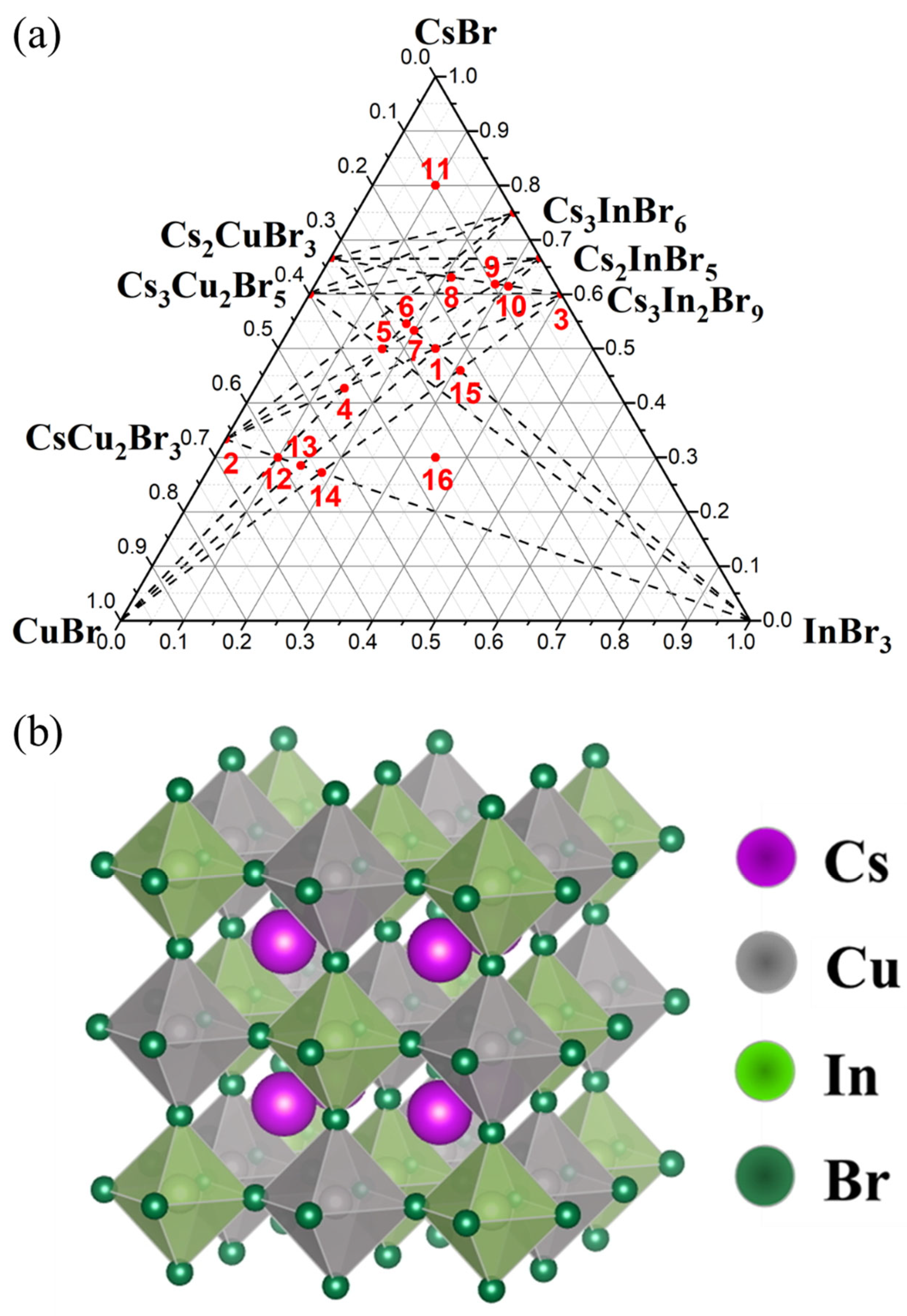
2.2. Synthesis of Compounds in CsBr-CuBr-InBr3 Triangle

Ampoule synthesis served as the main approach in the sample preparation. Various compositions of simple and binary bromides were taken as precursors. Cesium bromide was taken after Sigma-Aldrich (99.999%). Copper (I) bromide was synthesized by the solution method via a redox reaction, according to Equation (1). Sodium sulfite (“Rushim”, pure) with sulfuric acid (“Sigma Tech”, pure) as a source of sulfur oxide (IV) is also used. A strong flow of pure SO2 was passed into a solution of appropriate amounts of pure copper (II) sulfate pentahydrate (“Rushim”, pure) and potassium bromide (“Reahim”, extra pure) in distilled water at moderate heating (T = 60 °C) for 2 h. In this case, it is a light precipitate in the form of thin yellowish-white crystals. Carefully protecting the precipitate from the action of daylight, it is filtered off 5–7 times, placed in boiled distilled water containing SO2, and filtered again. After that, the precipitate was washed with 96% alcohol and then treated in a nitrogen atmosphere at 60 °C.
2CuSO4∙5H2O + 2KBr + SO2 = 2CuBr + 2H2SO4 + K2SO4 + 8H2O
Indium bromide InBr3 was prepared by the wet-chemistry method using elementary indium (“RedkyMetal.RF”, 99.999%) and hydrobromic acid HBr (“Reahim”, analytical grade) as precursors [33,34,35].
The ampoules syntheses were carried out in closed quartz ampoules according to the technique discussed elsewhere [35]. The total weight of each sample was 2 g. The ampoules were sealed after their evacuation (0.072 bar).
A number of compositions in the CsBr-CuBr-InBr3 phase triangle of bromides were taken for analysis of phase equilibria, and the availability of a “double perovskite” was predicted theoretically (Figure 1a). The composition ‘1’ corresponds to the “double perovskite” Cs2CuInBr6 phase, according to Ref. [29]. The double perovskite Cs2CuInBr6 has a cubic structure with a space group Fm3̅m with a lattice constant of 10.9 Å. The unit cell of Cs2CuInBr6 consists of CuBr6 and InBr6 octahedra alternating along all three directions. And the B-site cations Cu+ and In3+ form an ordered structure of double perovskite, as shown in Figure 1b.
The weights of precursors, including cesium bromide, copper(I) bromide, and indium(III) bromide, per 1 g of the resulting sample weights are given in Table 1. The measurements were carried out using a semi-micro analytical balance GR-202 (A&D Company, Limited, Tokyo, Japan) at room temperature.
Samples of theoretically predicted composition Cs2CuInBr6 were synthesized by the solid-phase or heterophase ampoule methods. The annealings were carried out at T = 300–650 °C, and the duration was 96 h in most of the experiments, according to recent results reported by Kamilov et al. for a similar ternary system [35].

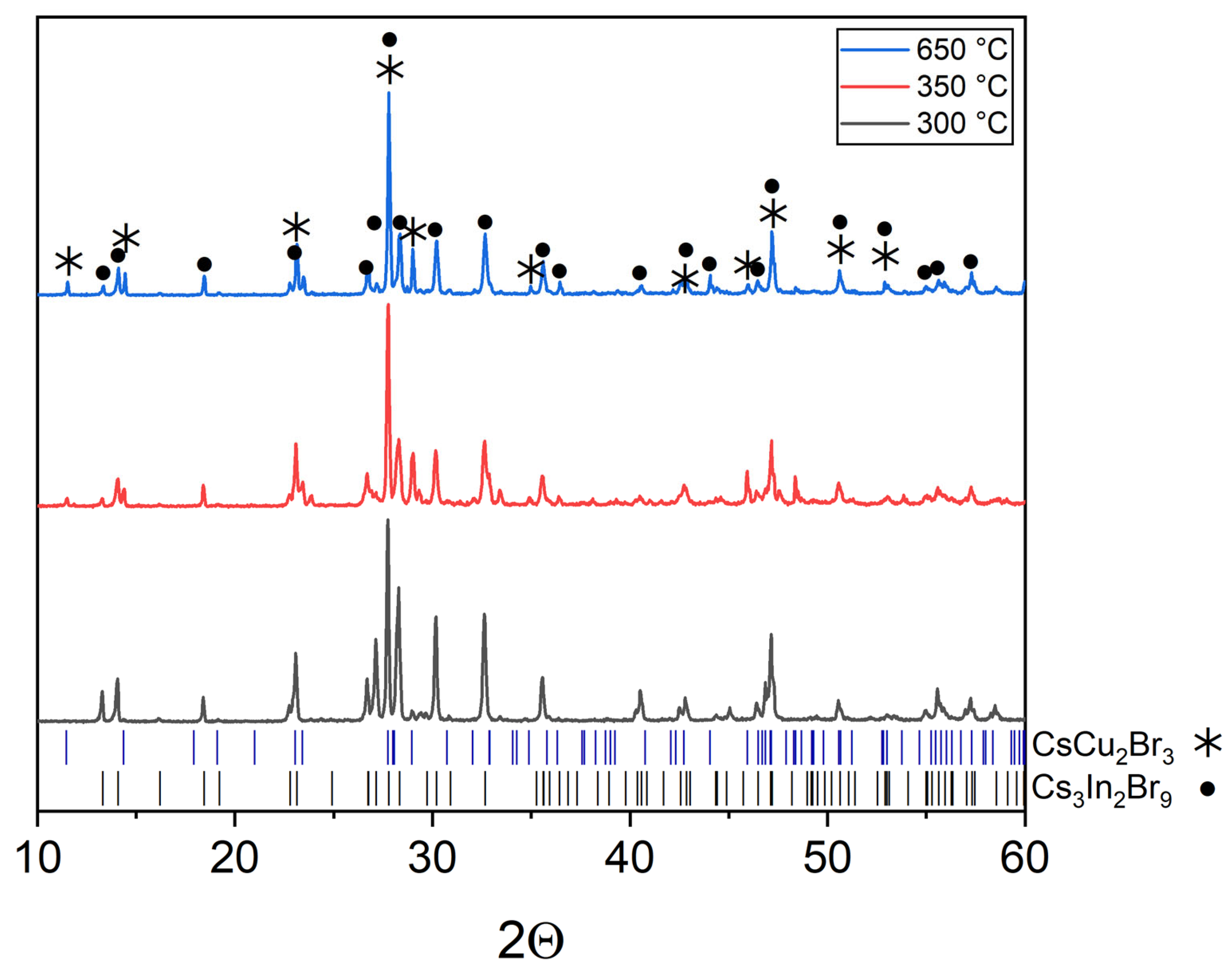
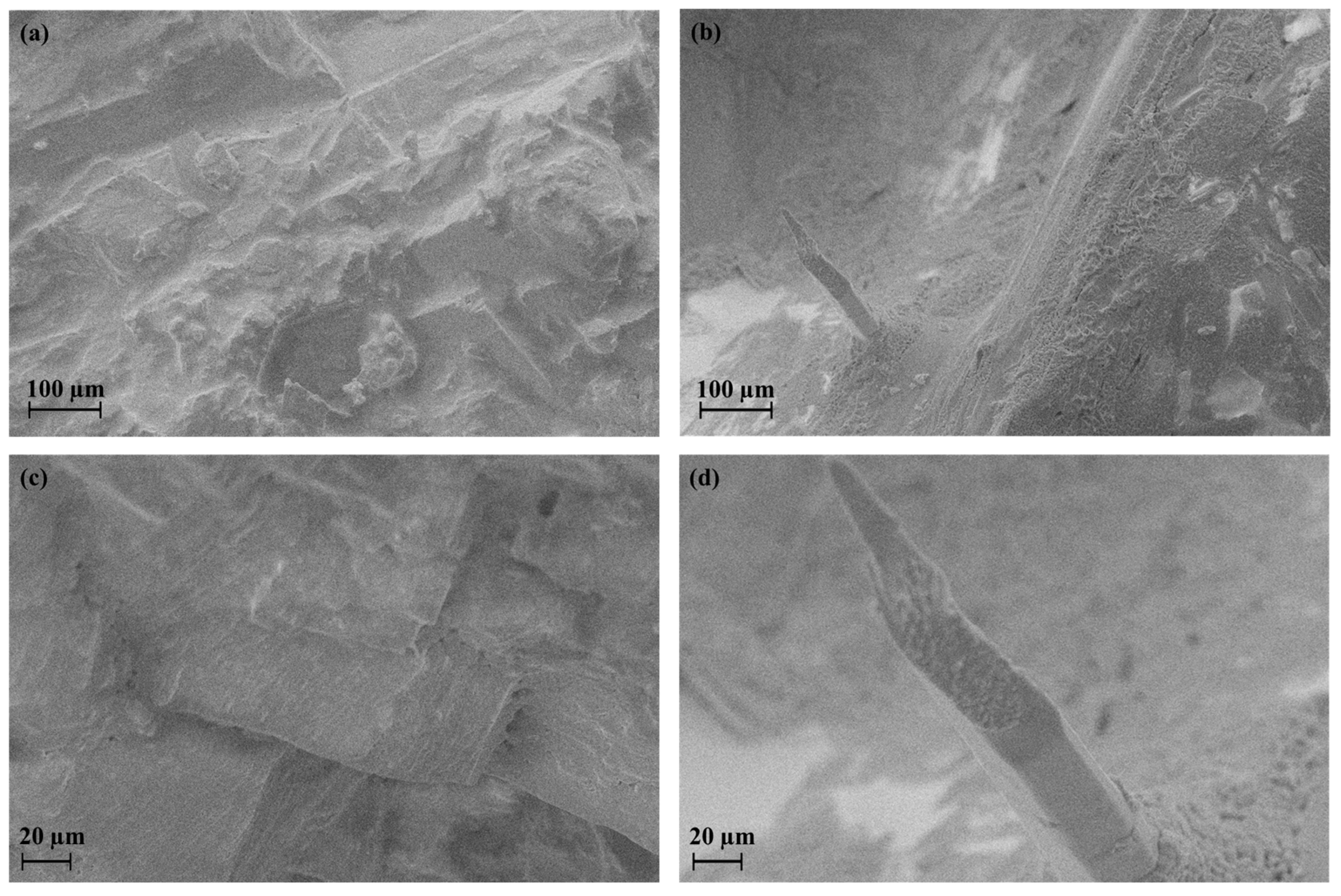
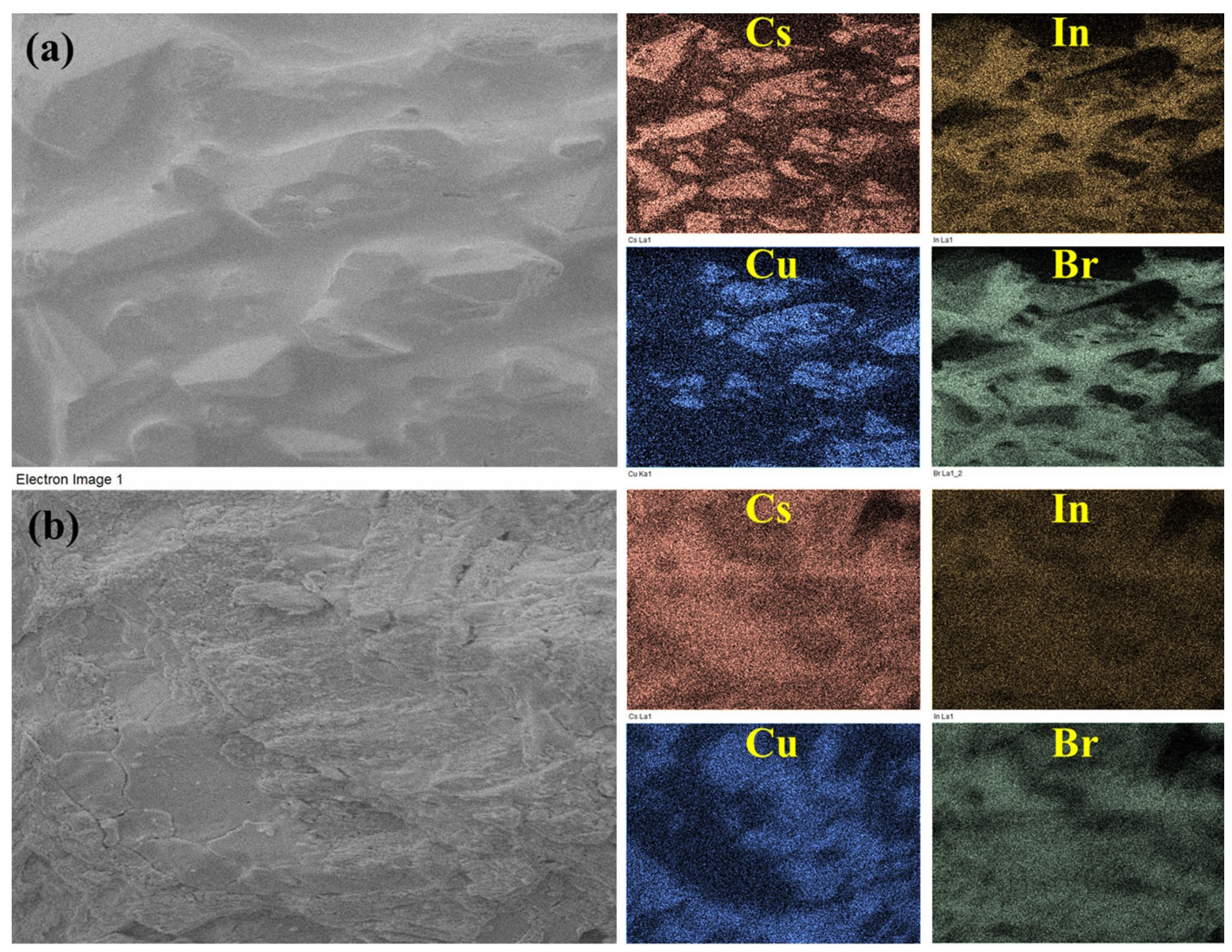
3. Results and Discussion

Three binary systems of single bromides are the sides of the phase triangle CsBr-CuBr-InBr3. In the CsBr–CuBr binary system, there are three phases–Cs2CuBr3 and CsCu2Br3 [36], Cs3Cu2Br5 [37], and in the CsBr–InBr3 system, three binary bromides, namely, Cs3In2Br9 [38], Cs3InBr6, and Cs2InBr5 [39] could be formed. No binary bromides are predicted for the binary CuBr–InBr3 system.
The “double perovskite” composition (point ‘1’ in the phase triangle) in CsBr-CuBr-InBr3 Gibbs’s triangle corresponds to a “double perovskite” composition Cs2CuInBr6. The synthesis has been performed at different temperatures to reach the most optimal thermodynamic parameters for the perovskite phase formation. Sintering at 300 °C leads to polycrystalline products, which are orange-colored powders. The samples annealed at 650 °C correspond to melt crystallization and are “single-piece” and orange-colored. No Cu2+ compounds are included as admixtures according to the ESR results of the samples.
The XRD data of the composition ‘1’ of the “double perovskite” Cs2CuInBr6 (Material Project ID: mp-1113481). The samples are not a single phase and correspond to a mixture of binary bromides, namely, cesium bromocuprate(I) and tricesium dibromoindate(III). Some reflections at the same 2Θ as for double halides, namely, CsCu2Br3 (PDF2 (38-850)) and Cs3In2Br9 (Springer materials ID: sd_1712349).
In the ternary diagram, the “double perovskite” phase belongs to three double sections, including CuBr–Cs2InBr5, InBr3–Cs2CuBr3, and CsCu2Br3-Cs3In2Br9, respectively.
According to the phase, XRD analysis performed (Figure 2), the Cs2CuInBr6 phase is not formed in the whole temperature range of 300–650 °C, but the sample ‘1’ includes two phases of binary bromides Cs3In2Br9 and CsCu2Br3. No single bromides have been found as a result of the full transformation to binary bromides Cs3In2Br9 and CsCu2Br3. It is also noticeable that the XRD patterns for the samples annealed at 350 °C and 650 °C are much more similar than for the samples annealed at 300 °C and 350 °C, respectively. Most likely, the eutectic temperature for the composition ‘1’ is in the temperature range of 300–350 °C.
Figure 3 shows the micromorphology of the samples synthesized at 300 °C and 650 °C, respectively. The composition ‘1’ annealed at 300 °C is rather uniform and is presented by layered orthorhombic crystals. The composition ‘1’ annealed at 650 °C has a different micromorphology demonstrating the crystallization of the Cs3In2Br9 phase as prismatic crystals surrounded by a euthectic mixture of uniform round-shaped grains of 1–2 µm. It is evident that the eutectic point is closer to bromocuprate(I) cesium composition because of its lower melting point in comparison to tricesium dibromoindate(III). The composition ‘1’ melted definitely at 650 °C gives larger crystals of Cs3In2Br9 in a matrix of eutectic mixture of smaller crystals.
In order to refine the stoichiometry in the course of ampoule synthesis, some of the samples have been additionally studied by the EDS method. Table 2 and Figure 4 show the results of EDS spectroscopy of samples synthesized at 300 °C and 650 °C, respectively. It is shown that the cation ratio of Cu/In is close to 1:1. It can be assumed that minor deviations from theoretical values can be associated with different morphology of the crystallites of the resulting phases. According to EDS imaging (Figure 4), the composition ‘1’ after a sintering at 300 °C includes prismatic crystallites of complex bromide of copper and cesium. This correlates with XRD data and could be related to CsCu2Br3 phase.
The Raman spectra of the samples synthesized at 300 °C and 650 °C are given in Figure 5a,b. The spectra contain well-defined characteristic modes related mostly to the Cs3In2Br9 phase. The most intensive modes are: ν (A1g)—165 cm−1, ν(Eg)—216 cm−1 and 111 cm−1 [40]. Most likely, this is the result of higher crystallinity (larger size of crystallites) for the Cs3In2Br9 phase.
A sample of the CsCu2Br3 (point ‘2’) binary bromide obtained at a temperature of 650 °C and an annealing time of 24 h is single-phase according to XRD data (Figure 6a). The sample Cs3In2Br9 (point ‘3’), synthesized at a temperature of 650 °C and an annealing time of 24 h, is obtained by crystallization from a melt. According to its XRD results, the sample is a single-phase and corresponds to the phase Cs3In2Br9 (Springer materials ID: sd_1712349). It’s identical to the sample synthesized by our group by the solid-phase method and reported elsewhere [41]. The Raman data for the sample (Figure 5d) also correspond well to the spectrum of the Cs3In2Br9 phase described by Zhou et al. [42] and later by Kamilov et al. [41].
Additional twelve compositions have been synthesized at the intersections of possible binary sections to analyze binary phase equilibria in the CsBr-CuBr-InBr3 ternary system. Namely, the intersection point of the CsCu2Br3-Cs3In2Br9 and CuBr-Cs3InBr6 sections (point ‘4’, obtained by displacement of bromides CsCu2Br3 and Cs3In2Br9), the CsCu2Br3-Cs2InBr5 and CuBr-Cs3InBr6 sections (point ‘5’), the Cs2CuBr3-InBr3 and CuBr-Cs2InBr5 (point ‘6’), the Cs2CuBr3-InBr3 and CsCu2Br3-Cs2InBr5 sections (point ‘7’), the Cs2CuBr3-Cs3In2Br9 and CuBr-Cs3InBr6 (point ‘8’), the Cs2CuBr3-Cs3In2Br9 and CsCu2Br3-Cs2InBr5 (point ‘9’), the Cs2CuBr3-Cs3In2Br9 and CuBr-Cs2InBr5 (point ‘10’), the CsCu2Br3-InBr3 and CuBr-Cs3InBr6 sections (point ‘12’), the CsCu2Br3-InBr3 and CuBr-Cs2InBr5 (point ‘13’), the CsCu2Br3-InBr3 and CuBr-Cs3In2Br9 (point ‘14’, obtained by displacement of bromides CuBr and Cs3In2Br9), the Cs2CuBr3-InBr3 and CuBr-Cs3In2Br9 (point ‘15’), and also point ‘11’ and point ‘16’ which are outside the intersections. The annealing temperature was 250–350 °C for points ‘8’ and ‘14’, 450 °C for point ‘11’, and 650 °C for points ‘4’–‘10’,’12’–’16’.
The XRD data of points ‘1’–‘4’ located on the CsCu2Br3-Cs3In2Br9 binary section contain only reflections of the CsCu2Br3 (PDF (77-1586)) and Cs3In2Br9 (Springer materials ID: sd_1712349) phases that indicates the stability of this section (Figure 7). Sample ‘4’ (the intersection of the CsCu2Br3-Cs3In2Br9 and CuBr-Cs3InBr6 sections, obtained by displacement of bromides CsCu2Br3 and Cs3In2Br9 phases), annealed at 650 °C, does not have reflections of the CuBr and Cs3InBr6 phases, which may indicate the instability of the CuBr-Cs3InBr6 quasi-binary section. As a result, the simulated “double perovskite” phase Cs2CuInBr6 is in the quasi-binary section CsCu2Br3-Cs3In2Br9. No complex bromide compounds are predicted for this binary system. As it has been discussed above, the expected eutectic point is closer to the CsCu2Br3 phase because of its lower melting point.
XRD of samples ‘5’, ‘6’, and ‘7’ are given in Figure 8. All three points are at the virtual intersections of the CsCu2Br3-Cs2InBr5 and CuBr-Cs3InBr6 sections (point ‘5’), the Cs2CuBr3-InBr3 and CuBr-Cs2InBr5 (point ‘6’), the Cs2CuBr3-InBr3 and CsCu2Br3-Cs2InBr5 sections (point ‘7’). The results show the instability of these intersections. Reflections of the most stable phases CsCu2Br3 (PDF2 (77-1586)), Cs3Cu2Br5 (PDF (01-072-9849)), and Cs3In2Br9 (Springer materials ID: sd_1712349) have been identified. Obviously, all three points are in a triangle of phases of binary bromides, namely, CsCu2Br3, Cs3Cu2Br5, and Cs3Cu2Br9. Point ‘8’ (Figure 9) is on the intersection of incisions of CuBr-Cs3InBr6 and Cs2CuBr3-Cs3In2Br9. Equilibrium (2) is assumed to exist:
3Cs2CuBr3 + Cs3In2Br9 = 6CuBr + 2Cs3InBr6
According to the phase analysis performed, sample ‘8’ synthesized from the simple bromides contains the phases Cs3In2Br9 (Springer materials ID: sd_1712349), Cs2CuBr3 (Maretial Project ID: mp-1226699), InBr3 (PDF2 (79-281)), CsBr (PDF2 (78-615)). Thus, the stability of these four phases under synthesis conditions is shown. Cs3InBr6 phase shown in the phase diagram CsBr–InBr3 is not stable if performed a solid-state synthesis or crystallized from the melt. Thus, we can conclude that the Cs3InBr6-CuBr section is not quasi-binary.
Points ‘8’, ‘9’, and ‘10’ are on the inclusion Cs2CuBr3-Cs3In2Br9 section (Figure 1a). Points ‘9’ and ‘10’ contain phases Cs3In2Br9 (Springer materials ID: sd_1712349) and Cs3Cu2Br5 (PDF (01-072-9849)) according to the XRD results (Figure 10). Apparently, during crystallization from the melt on the Cs2CuBr3-Cs3In2Br9 section, the formation of the Cs3Cu2Br5 phase is preferable, while solid-phase synthesis leads to Cs2CuBr3.
The XRD data of point ‘11’, which is outside the intersections and located in a triangle of CsBr–Cs2CuBr3–Cs3InBr6 phases (Figure 1), is shown in Figure 11. According to the XRD data, reflections of the CsBr (PDF2 (78-615)), Cs3Cu2Br5 (PDF (01-072-9849)), and Cs3In2Br9 (Springer materials ID: sd_1712349) phases are found. Apparently, the Cs3InBr6, Cs2InBr5, and Cs2CuBr3 phases are not stable at 450 °C, which is consistent with the data on the CsBr–CuBr [36] and CsBr–InBr3 [39] binary systems.
The XRD patterns of sample ‘14’ is on the intersection of incisions of CsCu2Br3-InBr3 and CuBr-Cs3In2Br9 are given in Figure 12. Reflection identification shows that the samples are not single-phase as expected. The diffractograms show the presence of reflections of complex bromides, namely, as CsCu2Br3 (PDF-2 (77-1586)), Cs3In2Br9 (Springer materials ID: sd_1712349), as well as a precursor CuBr (PDF-2 (6-292)) and InBr3 (PDF-2 (79-281)).
It can be assumed that there is an equilibrium described by Equation (3):
6CuBr + Cs3In2Br9 = 3CsCu2Br3 + 2InBr3
According to the experimental data, it is difficult to draw an unambiguous conclusion about the effect of temperature increase on the shift of equilibrium to the right or to the left since the number of reflections increases with a growth in the annealing temperature. The relative intensity of reflections changes, and reflections overlap each other. At the same time, based on single reflections, it can be seen that the relative intensity of the CuBr phase reflections decreases while the intensity of the main reflections of the CsCu2Br3, Cs3In2Br9, and InBr3 phases increases. Thus, it is most likely that equilibrium (3) shifts to the right with an increase in the annealing temperature. In this case, the increase in the intensity of reflections of the cesium bromoindate(III) phase can be explained by the formation of larger crystallites of this phase with increasing temperature.
Points ‘12’, ‘13’, ‘14’ (Figure 1) are located at the intersection of the CsCu2Br3-InBr3 section and the CuBr-Cs3InBr6, CuBr-Cs2InBr5, CuBr-Cs3In2Br9 sections, respectively. According to XRD data (Figure 12), the phase composition of these points includes the CuBr (PDF2 (6-292)), CsCu2Br3 (PDF-2 (77-1586)), and Cs3In2Br9 (Springer materials ID: sd_1712349) phases. On the other hand, the phase composition of point ‘15’ according to XRD data (Figure 13), consists of the phase CuBr, CsCu2Br3, and Cs3In2Br9, as well as for points ‘12’, ‘13’, ‘14’. Summarizing these results, we can conclude that points ‘12’–’15’ lie in a triangle consisting of CuBr, CsCu2Br3, and Cs3In2Br9 phases (Figure 1), which corresponds to the phase composition of all four points.
Also, the phase composition of point ‘16’ consists of the CuBr and Cs3Cu2Br9 phases due to the XRD data (Figure 14). This fact confirms the stability of the CuBr-Cs3In2Br9 section, point ‘15’ (intersection of incisions CuBr-Cs3In2Br9 and Cs2CuBr3-InBr3), point ‘16’.
The deepest minimum in the heating DSC curve is observed at 330 °C (603 K). This temperature is lower than the melting point of the CsCu2Br3 phase (congruent melting at 351 °C (624 K) [42]. There is no Cs3In2Br9 compound in the known phase diagram [43], and there are no data on the exact melting point of the Cs3In2Br9 phase. At higher temperatures, features on the DSC curve for this composition do not exist up to a temperature of 450 °C. It can be assumed that the temperature corresponds to the liquidus in the binary system CsCu2Br3-Cs3In2Br9. A relatively small minimum at 309 °C (582 K) may correspond to a phase transition for one of the components of the system (possibly Cs3In2Br9) or to a solidus isotherm in the quasi-binary system CsCu2Br3-Cs3In2Br9.
The cooling curve of sample ‘4’ has two maxima. The first (right) one, at 325 °C (598 K), is wider, less intense, and probably corresponds to the beginning of the crystallization process of Cs3In2Br9. The next (left) one at 294 °C (567 K), more intense, corresponds to the solidus isotherm for the quasi-binary system CsCu2Br3-Cs3In2Br9 and the end of crystallization process (probably, crystallization of the eutectic composition). According to the XRD results, the phase composition of sample ‘4’ has not changed.
The heating DSC curve for a batch sample containing CuBr and Cs3In2Br9 in stoichiometric amounts corresponding to composition ‘14’ is shown in Figure 15b. A very weak endothermic effect is found at 300 °C (573 K). The deepest minimum on the melting curve is observed at 328 °C (601 K) and, most likely, corresponds to a liquidus temperature for the given composition. At higher temperatures (up to 450 °C), no other endothermic effects are observed. There are three exothermic maxima on the cooling curve, the profile, two of which repeat the results for the heating curve of the two-phase system CsCu2Br3-Cs3In2Br9.
A new sharp crystallization maximum also appears on the cooling curve at 298 °C (571 K), which can be explained by the crystallization of the third phase, which may be InBr3 or CsCu2Br3. The appearance of a new crystallization maximum can be associated with the solid-state process described by Equation (2) above. The narrow maximum at 294 °C (567 K) could be a solidus temperature for the quasi-binary system of CuBr-Cs3In2Br9 or, probably, CsCu2Br3-Cs3In2Br9 (see above for the reasons). The DSC data for the composition ‘14’ are in good agreement with the XRD results reported for this composition above.

4. Conclusions

Investigation of the phase equilibria discussed in the article is rather rough but gives important information about the processes which take part in the ternary systems on heating. The predicted theoretically bromindate(III) Cs2CuInBr6 with a double perovskite structure has not been obtained yet using a direct synthesis from primary or double bromides as precursors, even under a rather long sintering process. The reason for this instability of the phase originates from the high stability of corresponding binary bromides Cs3In2Br9 and CsCu2Br3.
At the same time, the current research sheds light on the phase composition and chemical processes in the phase triangle of bromides CsBr-CuBr-InBr3. The quasi-binarity of the CsCu2Br3-Cs3In2Br9 and Cs2CuBr3-Cs3In2Br9 section is experimentally shown under the conditions of solid-phase synthesis. A possibility of the solid-phase reaction Cs3In2Br9 + CuBr = CsCu2Br3 + InBr3 is shown by the method of ampoule synthesis. As the temperature rises, the reaction equilibrium shifts to the right. It is shown that during crystallization from the melt on the Cs2CuBr3-Cs3In2Br9 section, the formation of the Cs3In2Br9 and Cs3Cu2Br5 phases is preferable. Thereby, the CsBr-CuBr-InBr3 ternary system triangulates with the next eutectic-type quasi-binary sections Cs3Cu2Br5-Cs3In2Br9, CsCu2Br3-Cs3In2Br9, and CuBr-Cs3In2Br9, forming four triangles CsBr-Cs3Cu2Br5-Cs3In2Br9, CsCu2Br3-Cs3Cu2Br5-Cs3In2Br9, CuBr-CsCu2Br3-Cs3In2Br9, CuBr-Cs3In2Br9-InBr3.

Author Contributions

Conceptualization, A.V.G. and R.K.K.; methodology, A.V.G. and R.K.K.; formal analysis, R.K.K. and J.Z.Y.; investigation, R.K.K., J.Z.Y., and A.V.K.; resources, A.V.K. and A.V.G.; writing—original draft preparation, R.K.K.; writing—review and editing, A.V.G. and R.K.K.; visualization, R.K.K. and A.V.K.; supervision, A.V.G.; project administration, A.V.G.; funding acquisition, A.V.G. All authors have read and agreed to the published version of the manuscript.

Funding

This research was supported by the Russian Science Foundation (RSF) (grant 22-23-00585).

Institutional Review Board Statement

Not applicable.

Informed Consent Statement

Not applicable.

Data Availability Statement

Not applicable.

Acknowledgments

Authors are grateful to their colleagues Dmitry O. Charkin, Shodruz T. Umedov, and Alexander A. Lagutin (Lomonosov Moscow State University) for their assistance with quartz sealing.

Conflicts of Interest

The authors declare no conflict of interest.

References

  1. Sirotkin, O.S.; Sirotkin, R.O.; Shibaev, P.B. Effect of the character of homo- and heteronuclear chemical bond on the intermolecular interaction energy and properties of halogens and hydrogen halides. Russ. J. Inorg. Chem. 2011, 56, 1104–1108. [Google Scholar] [CrossRef]
  2. Umedov, S.T.; Grigorieva, A.V.; Lepnev, S.L.; Knotko, A.V.; Koji, N.; Shinichi, O.; Shevelkov, A.V. Indium Doping of Lead-Free Perovskite Cs2SnI6. Front. Chem. 2020, 8, 564. [Google Scholar] [CrossRef] [PubMed]
  3. Kojima, A.; Teshima, K.; Miyasaka, T.; Shirai, Y. Novel photoelectrochemical cell with mesoscopic electrodes sensitized by lead-halide compounds (2). In Proceedings of the 210th ECS Meeting, Cancun, Mexico, 29 October–3 November 2006. [Google Scholar]
  4. Kojima, A.; Teshima, K.; Shirai, Y.; Miyasaka, T. Organometal halide perovskites as visible-light sensitizers for photovoltaic cells. J. Am. Chem. Soc. 2009, 131, 6050–6051. [Google Scholar] [CrossRef]
  5. Kim, H.-S.; Lee, C.-R.; Im, J.-H.; Lee, K.-B.; Moehl, T.; Marchioro, A.; Moon, S.-J.; Humphry-Baker, R.; Yum, J.-H.; Moser, J.E.; et al. Lead Iodide perovskite sensitized all-solid-state submicron thin film mesoscopic solar cell with effciency exceeding 9%. Sci. Rep. 2012, 2, 591. [Google Scholar] [CrossRef] [PubMed]
  6. Lee, M.M.; Teuscher, J.; Miyasaka, T.; Murakami, T.N.; Snaith, H.J. Efficient hybrid solar cells based on meso-superstructured organometal halide perovskites. Science 2012, 338, 643–647. [Google Scholar] [CrossRef]
  7. National Renewable Energy Laboratory. Best Research Cell Efficiencies. Available online: https://www.nrel.gov/pv/assets/pdfs/best-research-cell-efficiencies-rev220630.pdf (accessed on 30 June 2022).
  8. Stranks, S.D.; Snaith, H.J. Metal-halide perovskites for photovoltaic and light-emitting devices. Nat. Nanotechnol. 2015, 10, 391–402. [Google Scholar] [CrossRef]
  9. Cho, H.; Jeong, S.H.; Park, M.H.; Kim, Y.H.; Wolf, C.; Lee, C.L.; Heo, J.H.; Sadhanala, A.; Myoung, N.; Yoo, S.; et al. Overcoming the electroluminescence efficiency limitations of perovskite light-emitting diodes. Science 2015, 350, 1222–1225. [Google Scholar] [CrossRef]
  10. Jin, X.; Ma, K.; Gao, H. Tunable Luminescence and Enhanced Polar Solvent Resistance of Perovskite Nanocrystals Achieved by Surface-Initiated Photopolymerization. J. Am. Chem. Soc. 2022, 144, 20411–20420. [Google Scholar] [CrossRef]
  11. Zhu, H.; Fu, Y.; Meng, F.; Wu, X.; Gong, Z.; Ding, Q.; Gustafsson, M.V.; Trinh, M.T.; Jin, S.; Zhu, X. Lead halide perovskite nanowire lasers with low lasing thresholds and high quality factors. Nat. Mater. 2015, 14, 636–642. [Google Scholar] [CrossRef]
  12. Chu, L.; Hu, R.; Liu, W.; Ma, Y.; Zhang, R.; Yang, J.; Li, X. Screen printing large-area organometal halide perovskite thin films for efficient photodetectors. Mater. Res. Bull. 2018, 98, 322. [Google Scholar] [CrossRef]
  13. Zhang, F.; Yang, B.; Zheng, K.; Yang, S.; Li, Y.; Deng, W.; He, R. Formamidinium lead bromide (FAPbBr3) perovskite microcrystals for sensitive and fast photodetectors. Nano-Micro Lett. 2018, 10, 43. [Google Scholar] [CrossRef] [PubMed]
  14. Shestimerova, T.A.; Bykov, M.A.; Grigorieva, A.V.; Wei, Z.; Dikarev, E.V.; Shevelkov, A.V. Synthesis and characterization of amantadinium iodoacetatobismuthate, a hybrid compound with mixed iodide–carboxylate anions. Mendeleev Commun. 2022, 32, 194–197. [Google Scholar] [CrossRef]
  15. Nah, Y.; Solanki, D.; Kim, D.H. All-inorganic non-perovskite copper halides for light emission. Cell Rep. Phys. Sci. 2022, 3, 101171. [Google Scholar] [CrossRef]
  16. Li, Y.; Shi, Z.; Liang, W.; Wang, L.; Li, S.; Zhang, F.; Ma, Z.; Wang, Y.; Tian, Y.; Wu, D.; et al. Highly stable and spectrum-selective ultraviolet photodetectors based on lead-free copper-based perovskites. Mater. Horiz. 2020, 7, 530–540. [Google Scholar] [CrossRef]
  17. Li, Z.; Liu, X.; Zuo, C.; Yang, W.; Fang, X. Supersaturation-Controlled Growth of Monolithically Integrated Lead-Free Halide Perovskite Single-Crystalline Thin Film for High-Sensitivity Photodetectors. Adv. Mater. 2021, 33, 2103010. [Google Scholar] [CrossRef]
  18. Babayigit, A.; Ethirajan, A.; Muller, M.; Conings, B. Toxicity of organometal halide perovskite solar cells. Nat. Mater. 2016, 75, 247–251. [Google Scholar] [CrossRef] [PubMed]
  19. Babayigit, A.; Thanh, D.D.; Ethirajan, A.; Manca, J.; Muller, M.; Boyen, H.-G.; Conings, B. Assessing the toxicity of Pb- and Sn-based perovskite solar cells in model organism Danio rerio. Sci. Rep. 2016, 6, 18721. [Google Scholar] [CrossRef]
  20. Conings, B.; Drijkoningen, J.; Gauguelin, N.; Babayigit, A.; D’Haen, J.; D’Olieslaeger, L.; Ethirajan, A.; Verbeeck, J.; Manca, J.; Mosconi, E.; et al. Intrinsic Thermal Instability of Methylammonium Lead Trihalide Perovskite. Adv. Energy Mater. 2015, 5, 1500477. [Google Scholar] [CrossRef]
  21. Juarez-Perez, E.J.; Ono, L.K.; Maeda, M.; Jiang, Y.; Hawash, Z.; Qi, Y. Photodecomposition and thermal decomposition in methylammonium halide lead perovskites and inferred design principles to increase photovoltaic device stability. J. Mater. Chem. A 2018, 6, 9604–9612. [Google Scholar] [CrossRef]
  22. Bryant, D.; Aristidou, N.; Pont, S.; Sanchez-Molina, I.; Chotchunangatchaval, T.; Wheeler, S.; Durrant, J.R.; Haque, S.A. Light and oxygen induced degradation limits the operational stability of methylammonium lead triiodide perovskite solar cells. Energy Environ. Sci. 2016, 9, 1655–1660. [Google Scholar] [CrossRef]
  23. Wilks, R.G.; Bar, M. Perovskite solar cells: Danger from within. Nat. Energy 2017, 2, 16204. [Google Scholar] [CrossRef]
  24. Volonakis, G.; Haghighirad, A.A.; Milot, R.L.; Sio, W.H.; Filip, M.R.; Wenger, B.; Johnston, M.B.; Herz, L.M.; Snaith, H.J.; Giustino, F. Cs2InAgCl6: A New Lead-Free Halide Double Perovskite with Direct Band Gap. J. Phys. Chem. Lett. 2017, 8, 772–778. [Google Scholar] [CrossRef] [PubMed]
  25. Cheng, P.; Wu, T.; Li, Y.; Jiang, L.; Deng, W.; Han, K. Combining theory and experiment in the design of a lead-free ((CH3NH3)2AgBiI6) double perovskite. New J. Chem. 2017, 41, 9598–9601. [Google Scholar] [CrossRef]
  26. Luo, J.; Wang, X.; Li, S.; Liu, J.; Guo, Y.; Niu, G.; Yao, L.; Fu, Y.; Gao, L.; Dong, Q.; et al. Efficient and stable emission of warm-white light from lead-free halide double perovskites. Nature 2018, 563, 541–545. [Google Scholar] [CrossRef]
  27. Filip, M.R.; Hillman, S.; Haghighirad, A.A.; Snaith, H.J.; Giustino, F. Band gaps of the lead-free halide double perovskites Cs2BiAgCl6 and Cs2BiAgBr6 from theory and experiment. J. Phys. Chem. Lett. 2016, 7, 2579–2585. [Google Scholar] [CrossRef] [PubMed]
  28. McClure, E.T.; Ball, M.R.; Windl, W.; Woodward, P.M. Cs2AgBiX6 (X = Br, Cl): New visible light absorbing, lead-free halide perovskite semiconductors. Chem. Mater. 2016, 28, 1348–1354. [Google Scholar] [CrossRef]
  29. Zhao, X.G.; Yang, D.; Sun, Y.; Li, T.; Zhang, L.; Yu, L.; Zunger, A. Cu–In Halide Perovskite Solar Absorbers. J. Am. Chem. Soc. 2017, 139, 6718–6725. [Google Scholar] [CrossRef] [PubMed]
  30. Li, Z.; Xu, Q.; Sun, Q.; Hou, Z.; Yin, W. Stability Engineering of Halide Perovskite via Machine Learning. arXiv 2018, arXiv:1803.06042. [Google Scholar]
  31. Zheng, R.; Wang, Y.; Pan, J.; Malik, H.A.; Zhang, H.; Jia, C.; Weng, X.; Xie, J.; Deng, L. Toward easy-to-assemble, large-area smart windows: All-in-one cross-linked electrochromic material and device. ACS Appl. Mater. Interfaces 2020, 12, 27526–27536. [Google Scholar] [CrossRef]
  32. Xiao, Z.; Du, K.; Meng, W.; Mitzi, D.; Yan, Y. Chemical Origin of the Stability Difference between Cu(I)- and Ag(I)-Based Halide Double Perovskites. Angew. Chem. Int. Ed. 2017, 56, 12107–12111. [Google Scholar] [CrossRef]
  33. Ensslin, F.; Dreyer, H.Z. Über einige Salze des Indiums. I. Anorg. Allg. Chem. 1942, 249, 119–132. [Google Scholar] [CrossRef]
  34. Ensslin, F.; Ziemeck, B.; DeSchaepdryver, L.Z. Zur Chemie des Indiums. VI. Die Löslichkeit von Indium(III)-chlorid, Indium(III)-bromid und Indium(III)-jodid im Wasser bei verschiedenen Temperaturen. Anorg. Chem. 1947, 254, 293–296. [Google Scholar] [CrossRef]
  35. Du, K.; Meng, W.; Wang, X.; Yan, Y.; Mitzi, D. Bandgap Engineering of Lead-Free Double Perovskite Cs2AgBiBr6 through Trivalent Metal Alloying. Angew. Chem. Int. Ed. 2017, 56, 8158–8162. [Google Scholar] [CrossRef] [PubMed]
  36. Wojakowska, A.; Krzyżak, E.; Wojakowski, A. Phase diagram for the CuBr–CsBr system. Thermochim. Acta 2000, 344, 55–59. [Google Scholar] [CrossRef]
  37. Huang, X.; Wang, S.; Devakumar, B.; Ma, N. One-step low-temperature solid-state synthesis of lead-free cesium copper halide Cs3Cu2Br5 phosphors with bright blue emissions. Mater. Today Chem. 2022, 23, 100678. [Google Scholar] [CrossRef]
  38. Meyer, G.Z. Zur Kenntnis der Chloro- und Bromo-Indate (III). A3In2Cl9 (A = Cs, Rb, In, Tl) und Cs3In2Br9−xClx (x = 0, 3, 6, 7, 8). Anorg. Allg. Chem. 1978, 445, 140–146. [Google Scholar] [CrossRef]
  39. Dudareva, A.G.; Bogatov, Y.E.; Ivanov-Emin, B.N.; Fedorov, P.I. Study of the interaction of indium tribromide with cesium bromide. J. Inorg. Chem. 1971, XVI, 2586. [Google Scholar]
  40. Zhou, L.; Liao, J.-F.; Huang, Z.-G.; Wei, J.-H.; Wang, X.-D.; Li, W.-G.; Su, C.-Y. Highly Red Emissive Lead-Free Indium-Based Perovskite Single Crystal for Sensitive Water Detection. Angew. Chem. Int. Ed. 2019, 58, 5277–5281. [Google Scholar] [CrossRef]
  41. Kamilov, R.K.; Yuldoshev, J.Z.; Knotko, A.V.; Grigorieva, A.V. Phase Equilibria in Ternary System CsBr-AgBr-InBr3. Materials 2023, 16, 559. [Google Scholar] [CrossRef]
  42. Jagner, S.; Helgesson, G. On the coordination number of the metal in crystalline halogenocuprates(I) and halogenoargentates(I). Adv. Inorg. Chem. 1991, 37, 1–45. [Google Scholar]
  43. Dudareva, A.G.; Bogatov, Y.E.; Konstandia, A.; Ivanov-Emin, B.N.; Fedorov, P.I. Physicochemical study of the interaction of indium tribromide with silver, zinc and lead(II) bromides in a melt. Chem. Chem. Technol. 1971, XIV, 1299. [Google Scholar]
Figure 1. Gibbs triangle for the (a) CsBr-CuBr-InBr3 with selected compositions marked as points, and (b) a 2 × 2 unit cell of the double perovskite Cs2CuInBr6.
Materials 16 03744 g001
Figure 2. The diffraction pattern for the theoretical composition Cs2CuInBr6.
Materials 16 03744 g002
Figure 3. SEM images of composition ‘1’ obtained by the ampoule method at (a,c) 300 °C (b,d) 650 °C.
Materials 16 03744 g003
Figure 4. Element distribution map of composition ‘1’ obtained by the ampoule method at (a) 300 °C (b) 650 °C.
Materials 16 03744 g004
Figure 5. Raman spectra of samples of the theoretical composition Cs2CuInBr6 recently obtained by the ampoule method (a) ‘1’ at 300 °C (b) ‘1’ at 650 °C, (c) CsCu2Br3 and (d) Cs3In2Br9. Laser excitation 532 nm.
Materials 16 03744 g005
Figure 6. XRD data of (a) a sample ‘2’ (CsCu2Br3 phase), and (b) sample ‘3’ (Cs3In2Br9 phase).
Materials 16 03744 g006
Figure 7. XRD data for the points ‘1–4’, annealed at 650 °C (incision CsCu2Br3-Cs3In2Br9).
Materials 16 03744 g007
Figure 8. XRD data for point ‘5’ (intersection of incisions CsCu2Br3-Cs2InBr5 and CuBr-Cs3InBr6), point ‘6’ (intersection of incisions Cs2CuBr3-InBr3 and CuBr-Cs2InBr5), and point ‘7’ (intersection of incisions Cs2CuBr3-InBr3 and CsCu2Br3-Cs2InBr5).
Materials 16 03744 g008
Figure 9. XRD data for point ‘8’ (intersection of incisions Cs2CuBr3-Cs3In2Br9 and CuBr-Cs3InBr6).
Materials 16 03744 g009
Figure 10. XRD data for point ‘9’ (intersection of incisions Cs2CuBr3-Cs3In2Br9 and CsCu2Br3-Cs2InBr5) and point ‘10’ (intersection of incisions Cs2CuBr3-Cs3In2Br9 and CuBr-Cs2InBr5).
Materials 16 03744 g010
Figure 11. XRD results for point ‘11’.
Materials 16 03744 g011
Figure 12. XRD results for point ‘14’ (intersection of incisions CsCu2Br3-InBr3 and CuBr-Cs3In2Br9).
Materials 16 03744 g012
Figure 13. XRD data for point ‘12’ (intersection of incisions CsCu2Br3-InBr3 and CuBr-Cs3InBr6), point ‘13’ (intersection of incisions CsCu2Br3-InBr3 and CuBr-Cs2InBr5) and point ‘14’ (intersection of incisions CsCu2Br3-InBr3 and CuBr-Cs3In2Br9).
Materials 16 03744 g013
Figure 14. XRD patterns for the point ‘14’ (intersection of incisions CsCu2Br3-InBr3 and CuBr-Cs3In2Br9).
Materials 16 03744 g014
Figure 15. DSC data for the composition of (a) point ‘4’ at the intersection of the sections CuBr-Cs3InBr6, CsCu2Br3-Cs3In2Br9 synthesized from bromides CuBr and Cs3In2Br9 and (b) point ‘14’ at the intersection of the sections CuBr-Cs3In2Br9, CsCu2Br3-InBr3 obtained by displacement of binary bromides CsCu2Br3 and Cs3In2Br9. Black line is heating, and red line is cooling.
Materials 16 03744 g015
Table 1. Weighed weights of CsBr, CuBr, and InBr3 simple bromides for the samples, calculated per 1 g of the final product.
SampleMole Fraction of PrecursorsWeight of Precursors per 1 g of Product
n(CsBr)n(CuBr)n(InBr3)m(CsBr)m(CuBr)m(InBr3)
Point 10.5000.2500.2500.461(1)0.155(1)0.384(1)
Point 20.3300.660-0.426(1)0.572(2)-
Point 30.600-0.4000.474(1)-0.526(1)
Point 40.4270.4310.1420.448(1)0.305(1)0.248(1)
Point 50.4990.3350.1660.499(2)0.226(1)0.276(2)
Point 60.5330.2670.2000.510(2)0.172(1)0.318(2)
Point 70.5450.2740.1810.529(3)0.179(1)0.293(1)
Point 80.6310.1590.2100.580(2)0.099(1)0.322(1)
Point 90.6180.0960.2860.533(3)0.056(1)0.411(1)
Point 100.6140.0770.3090.520(1)0.044(1)0.436(2)
Point 110.8000.1000.1000.774(3)0.065(1)0.161(2)
Point 120.3000.6000.1000.344(1)0.465(2)0.191(1)
Point 130.2850.5710.1440.313(2)0.424(1)0.263(1)
Point 140.2720.5440.1840.288(1)0.388(1)0.324(1)
Point 150.4590.2310.3100.406(1)0.138(1)0.456(2)
Point 160.3000.3500.3500.268(4)0.211(1)0.521(3)
Table 2. The atomic percentages of the elemental composition of the samples obtained by the ampoule method at T = 300 °C and 650 °C.
Synthesis Temperature, °CCsCuInBrCation Ratio Cu/In
T = 300 °C (solid-phase synthesis)251211521.08
T = 650 °C (crystallization from the melt)251111531.00
Disclaimer/Publisher’s Note: The statements, opinions and data contained in all publications are solely those of the individual author(s) and contributor(s) and not of MDPI and/or the editor(s). MDPI and/or the editor(s) disclaim responsibility for any injury to people or property resulting from any ideas, methods, instructions or products referred to in the content.

