Article

Effect of Surface Modifications on Surface Roughness of Ti6Al4V Alloy Manufactured by 3D Printing, Casting, and Wrought

1
Doctoral School on Materials Sciences and Technologies, Óbuda University, Bécsi út. 96/B., H-1034 Budapest, Hungary
2
Dent-Art Technik Ltd., Csokonai u. 10., H-9024 Győr, Hungary
3
Department of Materials Science and Technology, Széchenyi István University, Egyetem tér 1., H-9026 Győr, Hungary
4
Bánki Donát Faculty of Mechanical and Safety Engineering, Óbuda University, Népszínház u. 8., H-1081 Budapest, Hungary
*
Author to whom correspondence should be addressed.
Materials 2023, 16(11), 3989; https://doi.org/10.3390/ma16113989
Submission received: 9 May 2023 / Revised: 22 May 2023 / Accepted: 23 May 2023 / Published: 26 May 2023

Abstract

:
This work aimed to comprehensively evaluate the influence of different surface modifications on the surface roughness of Ti6Al4V alloys produced by selective laser melting (SLM), casting and wrought. The Ti6Al4V surface was treated using blasting with Al2O3 (70–100 µm) and ZrO2 (50–130 µm) particles, acid etching with 0.017 mol/dm3 hydrofluoric acids (HF) for 120 s, and a combination of blasting and acid etching (SLA). It was found that the optimization of the surface roughness of Ti6Al4V parts produced by SLM differs significantly from those produced by casting or wrought processes. Experimental results showed that Ti6Al4V alloys produced by SLM and blasting with Al2O3 followed by HF etching had a higher surface roughness (Ra = 2.043 µm, Rz = 11.742 µm), whereas cast and wrought Ti6Al4V components had surface roughness values of (Ra = 1.466, Rz = 9.428 m) and (Ra = 0.940, Rz = 7.963 m), respectively. For Ti6Al4V parts blasted with ZrO2 and then etched by HF, the wrought Ti6Al4V parts exhibited higher surface roughness (Ra = 1.631 µm, Rz = 10.953 µm) than the SLM Ti6Al4V parts (Ra = 1.336 µm, Rz = 10.353 µm) and the cast Ti6Al4V parts (Ra = 1.075 µm, Rz = 8.904 µm).

1. Introduction

Osseointegration is a crucial factor in the success of dental and bone implants [1]. The term is generally understood to mean the formation of good interaction and functional connection between the surface of an implant and living bone tissue. As a result, the osseointegration process is strongly influenced by implant surface conditions such as surface roughness, chemical composition, charge, and energy [2]. The surface roughness is recognized as being the most important parameter influencing the speed and quality of osseointegration [3]. There are three categories of surface roughness based on size: macro-rough (10–30 µm), micro-rough (1–10 µm), and nano-rough (less than 1 µm). It is shown that an increase in the macro-, micro-, and nano-structured surface morphologies can improve osseointegration and enhance bone fixation [4,5]. Therefore, dental implant quality is directly dependent on surface conditions. To improve the osseointegration of dental implants, surface modification technologies are often used, such as blasting, polishing, chemicals (acid etching), and blasting plus acid etching (SLA) [6]. In blasting, hard ceramic particles are shot through a nozzle into the surface of implants utilizing compressed air at high speed. Acid etching treatment involves immersing the implants in a strong acid such as hydrofluoric acid (HF), nitric acid (HNO3), and/or sulphuric acid (H2SO4). The SLA is blasting followed by acid etching. Souza et al. [6] investigated the effect of blasting followed by acid etching (SLA) on the proteomic profile of layers of proteins adsorbed from saliva and blood plasma on the surface of a Ti-Zr alloy. Wang et al. [7] studied the impact of the processing parameters of electron beam melting (EBM) on the surface roughness of manufactured parts. Szymczyk-Zi’ołkowska et al. [8] investigated the influence of surface modifications (polishing, sandblasting, and acid-polishing) of Ti6Al4V implants produced by EBM on essential biological properties (wettability, cytotoxicity, and biofilm formation). They concluded that surface modification has a very strong influence on biological properties.
Titanium alloys, especially Ti6Al4V, are an important alloy for dental and orthopaedic implants owing to their excellent mechanical and biological properties [9]. In recent years, there has been increased interest in the use of 3D printing technology (selective laser melting, SLM) for the manufacture of Ti64 medical implants in place of powder metallurgy, wrought and casting processes [10,11]. In this work, the surface roughness in terms of arithmetic mean roughness (Ra) and mean depth of roughness (Rz) of Ti6Al4V samples manufactured by SLM, casting, and wrought were measured and compared. It was found that the surface roughness was different for each process.

2. Materials and Methods

2.1. Preparation of Ti6Al4V Samples

Polished cylindrical specimens of Ti6Al4V produced by three methods, SLM, casting and wrought, were used as the base material to study the surface roughness (Figure 1). The SLM Ti6Al4V specimens (Figure 1a) were fabricated using an SLM machine (Sisma MYSINT 100, Via dell’Industria, Vicenza, Italia) equipped with a 200 W fibre laser and a 55 µm laser spot. The dimensions of the SLM Ti6Al4V samples were 9 mm in diameter, and 50 mm in height. The optimal settings consisted of a continuous laser power of 125 W, a scanning speed of 1000 mm/s, and a layer thickness of 20 µm. A constant flow of 35 L of argon gas per minute was used for protection. The starting material for SLM Ti6Al4V specimens was Ti6Al4V plasma-atomized spherical powder (Gr.5) provided by LPW Technology (Runcorn UK), as shown in Figure 2. The chemical composition of Ti64 powder is shown in Table 1. The size distribution ranged from 15 to 45 µm.
The casting Ti6Al4V specimens (Figure 1b) were fabricated using a vacuum-pressure, plasma jet-heated casting machine. To ensure better chemical homogeneity, the 20 g ingots were remelted three times. A red copper mould was used to cast the experimental alloys used in this investigation. The mould was a truncated cone which had a 10 mm top diameter and 14 mm base diameter and a height of 50 mm (Figure 1b). In addition, Ti6Al4V drawn-rolled specimens (Figure 1c), in its wrought condition, were used as the base metal, and was 9 mm in diameter. After the manufacturing process, all samples were subjected to a polishing process. The polishing process was performed by a WP-EX 2000 machine (Wassermann, Hamburg, Germany) equipped with rag polishing discs. The samples were polished with a #1200 grit SiC foil.

2.2. Surface Modification Technologies

The manufactured and polished samples were divided into three groups: Casting, wrought, and 3D Printing. Each group was subjected to five types of surface modification (see below).
  • Etched in 0.017 mol/dm3 of hydrofluoric acid (HF) for 120 s at room temperature.
  • Blasted with Al2O3 particles (70–100 μm) with 4 bar blasting pressure. The blasting was performed with a Renfert Basic Quattro IS.
  • Blasted with Al2O3 particles and etched in 0.017 mol/dm3 of hydrofluoric acid (HF) for 120 s at room temperature.
  • Blasted with ZrO2 particles (50–130 μm) with 4 bar blasting pressure.
  • Blasted with ZrO2 and etched in 0.017 mol/dm3 of hydrofluoric acid (HF) for 120 s at room temperature.

2.3. Surface Roughness and Topography

The Ra and Rz surface roughness were determined using an ALICONA Infinite Focus equipped with Vision software. For each surface, five measurements were performed.

3. Results and Discussion

The values of surface roughness, Ra and Rz, for all specimens, are detailed in Table 2. It is revealed that 3D-printed (SLM) Ti6Al4V components are significantly different from cast and wrought Ti6Al4V parts when it comes to optimizing surface roughness by surface treatments such as Al2O3 blasting + HF etching. Ti6Al4V alloys produced by 3D printing and blasting with Al2O3 followed by HF etching exhibit the highest surface roughness compared to cast and wrought Ti6Al4V parts. The surface roughness of the 3D-printed samples is the roughest (Ra = 2.043, Rz = 11.742 µm), followed by the surface of the cast samples (Ra = 1.466, Rz = 9.428 µm), and the surface of the wrought samples (Ra = 0.940, Rz = 7.963 µm). The increase in surface roughness and the change in surface morphology of Ti alloys have been reported in sandblasting and acid etching processes [13].
It is interesting to note that the surface treatment (ZrO2 blasting + HF etching) of the wrought Ti6Al4V parts has a higher surface roughness (Ra = 1.631, Rz = 10.953 µm) than the cast parts (Ra = 1.075, Rz = 8.904 µm) and the 3D-printed ones (Ra = 1.336, Rz = 10.353 µm). The reason for this is probably the difference in the surface properties of the manufactured samples, which leads to different inclusion of ejected particles on the surface of the samples. In addition, as can be seen from Table 2, the HF etching process leads to a reduction in the surface roughness of the polished cast specimen (polishing and then etching) from (Ra = 0.503, Rz = 3.573 µm) to (Ra = 0.344, Rz = 2.723 µm), as the surface oxidation removes material, resulting in the ionization of atoms. In the wrought sample (polishing then etching), the roughness remains the same without an increase or decrease. On the other hand, the HF etching process leads to an increase in the surface roughness of the polished 3D sample (polishing and then etching). This is due to the high hardness of the 3D-printed sample, which reduces the oxidation process. It has been reported that the hardness of specimens manufactured by 3D printing (SLM) (377 HV) [10] is higher than those manufactured by casting (340 HV) [14] or wrought (306 HV) [15].

3.1. Casting

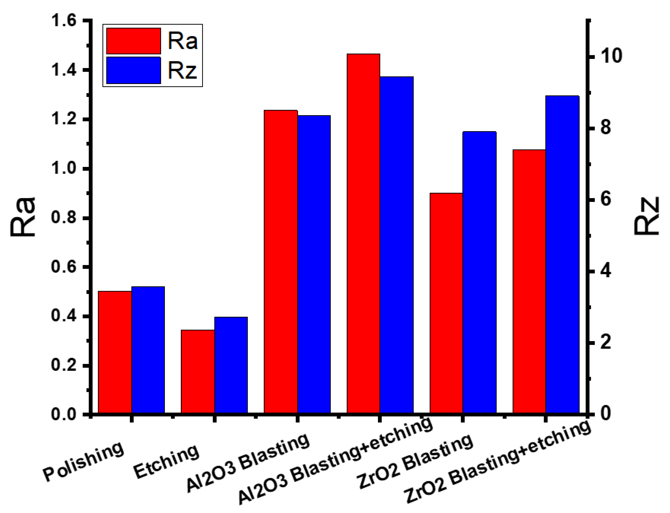
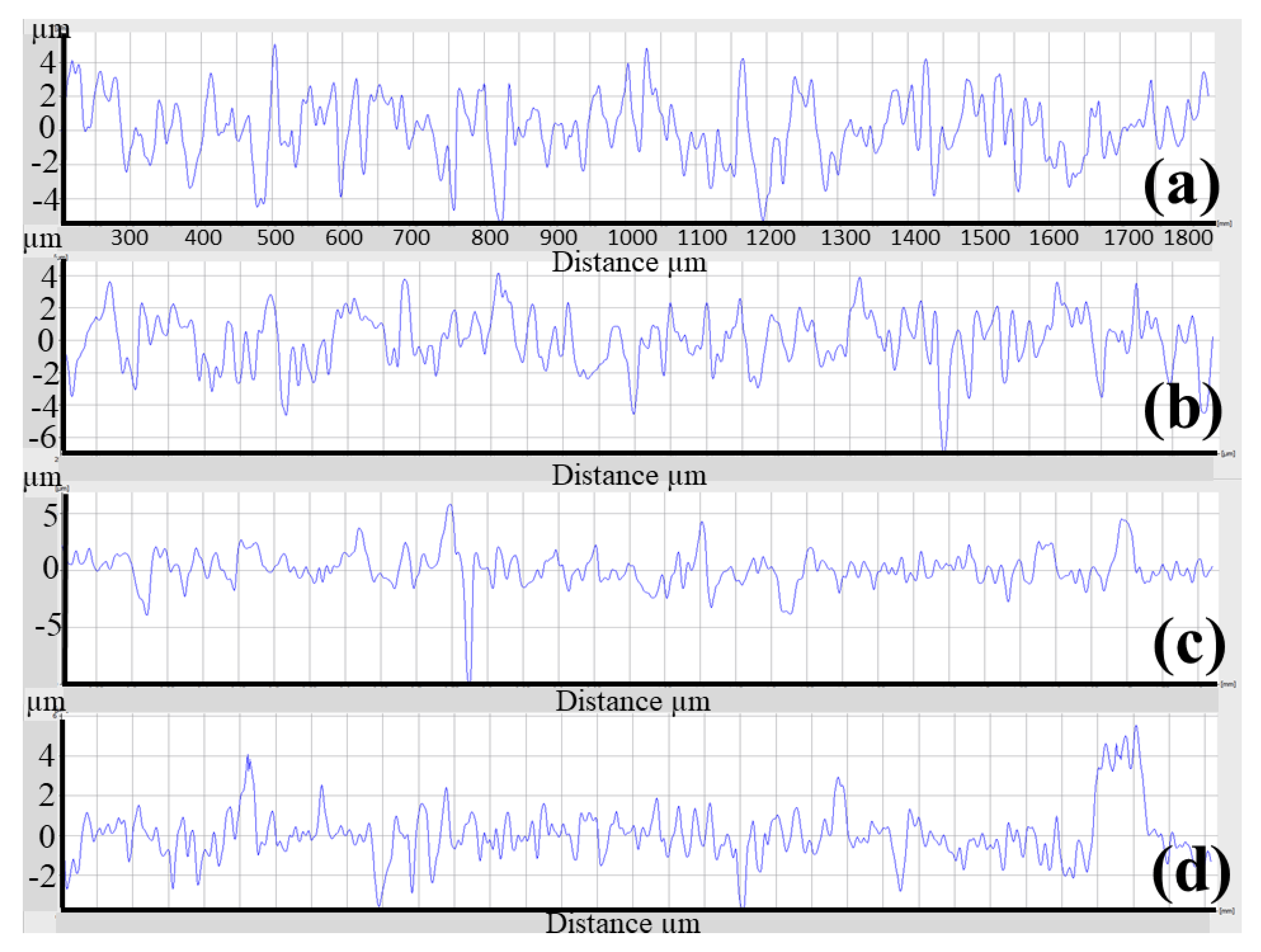
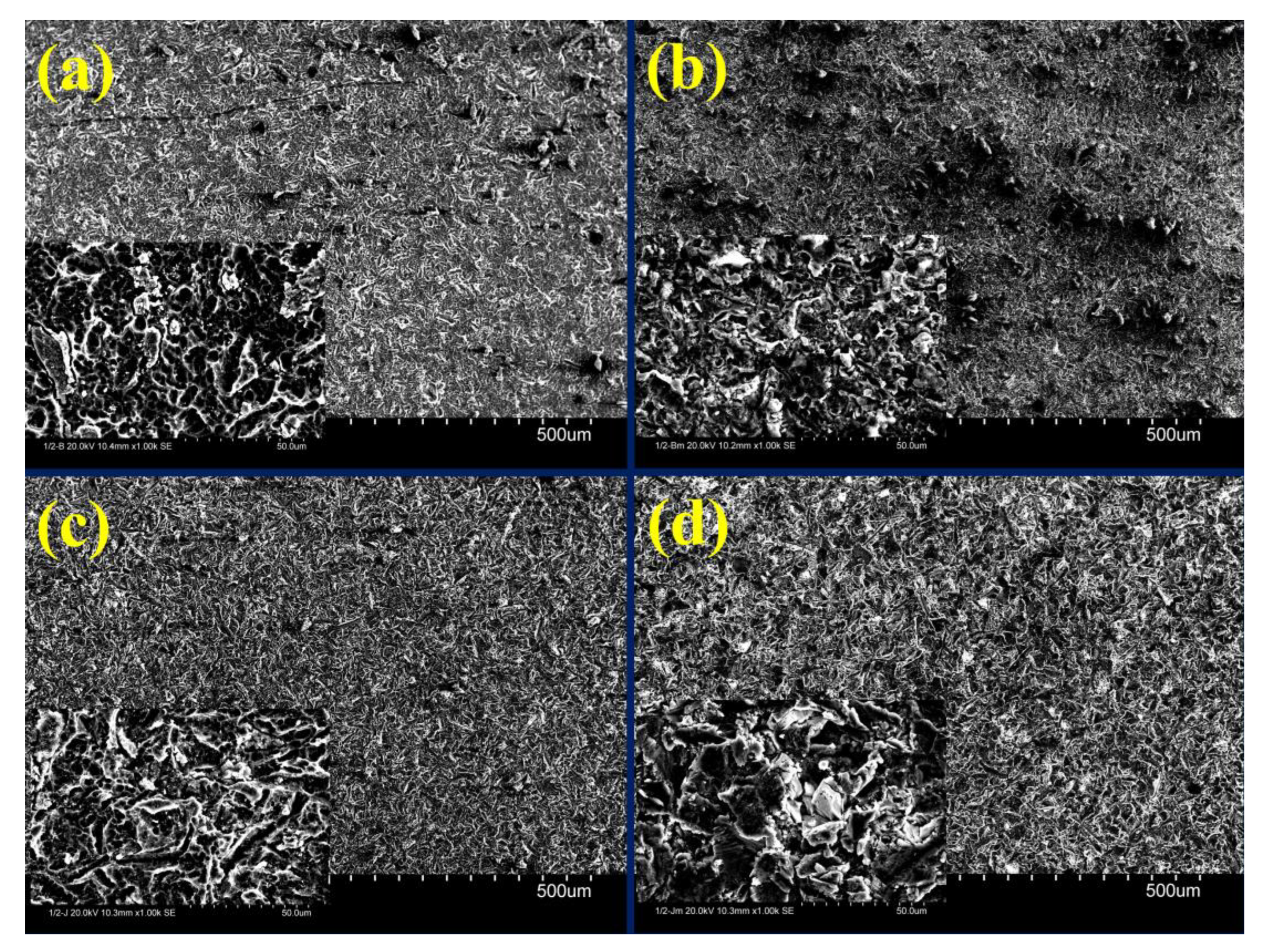
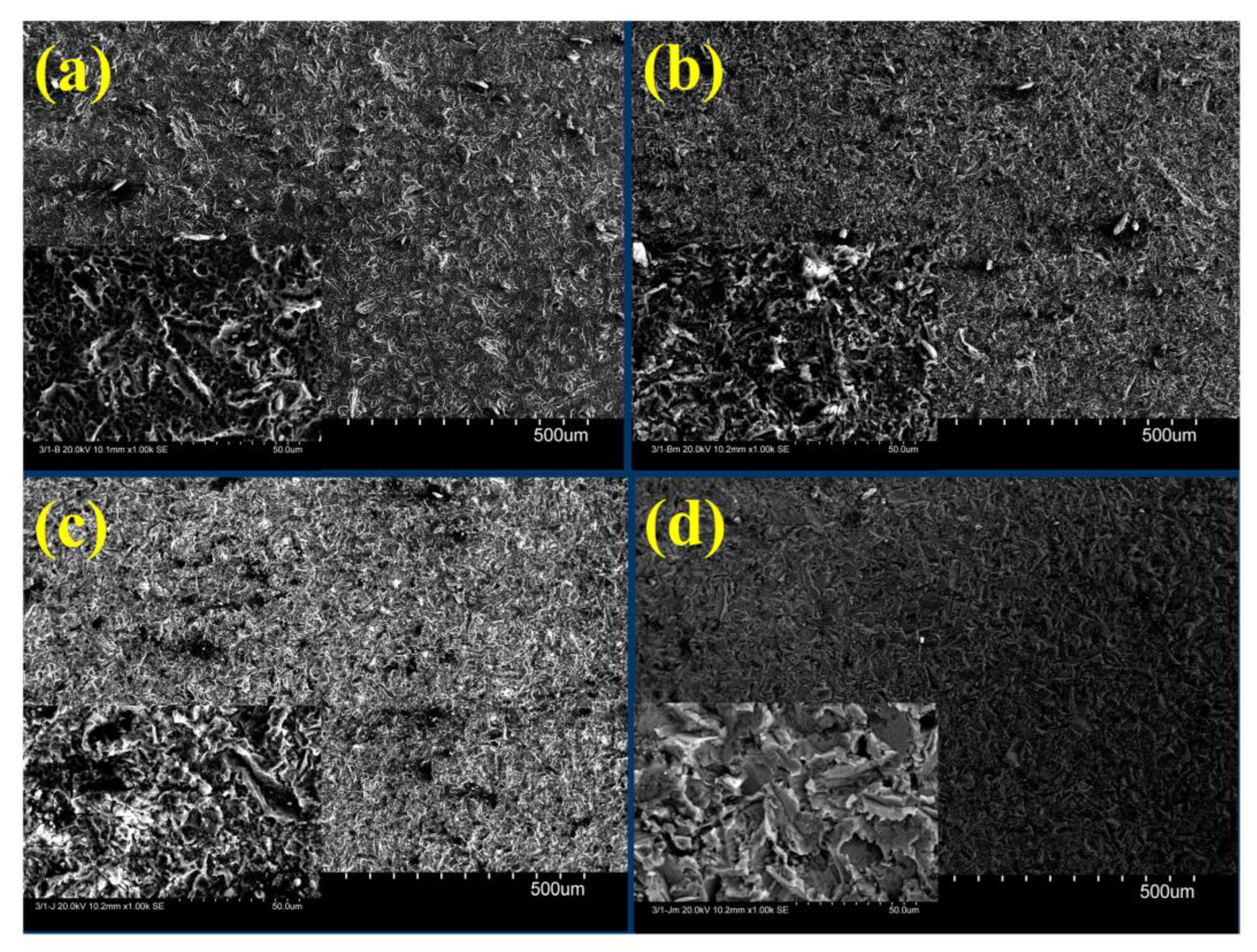
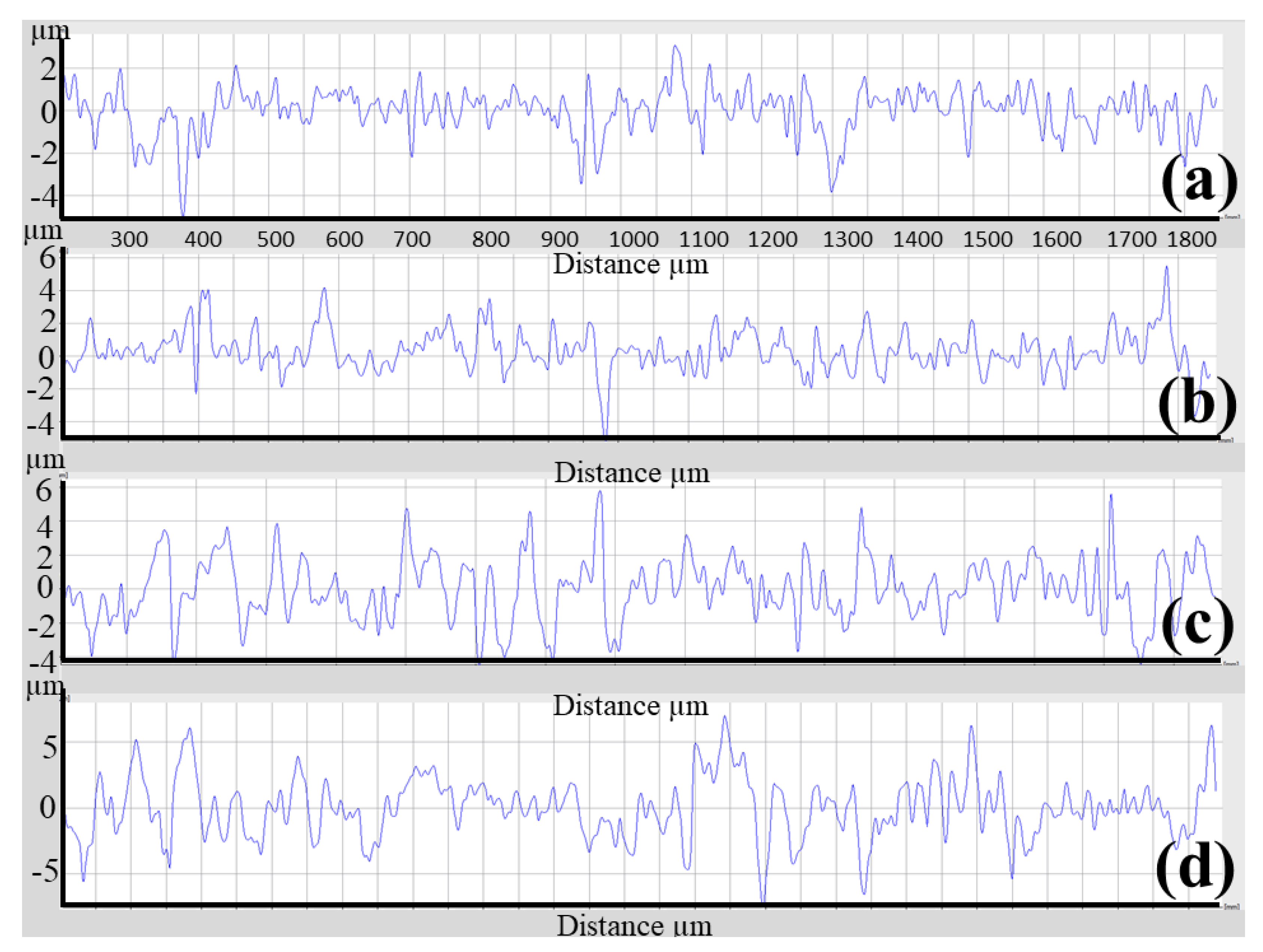
Figure 3 compares the surface roughness of the as-polished casted samples with samples after etching, blasting with Al2O3 or ZrO2, or a combination of these methods. As can be seen, the surface roughness was reduced from (Ra = 0.503, Rz = 3.573 µm) to (Ra = 0.344, Rz = 2.723 µm) by etching, and increased to (Ra = 1.236, Rz = 8.359 µm) by blasting with Al2O3, (Ra = 1.466, Rz = 9.428 µm) by blasting with Al2O3 and etching, (Ra = 0.900, Rz = 7.898 µm) by blasting with ZrO2, and (Ra = 1.075, Rz = 8.904 µm) by blasting with ZrO2 and etching. The highest surface roughness was achieved after a combination of blasting with Al2O3 and etching. This is confirmed by the surface roughness profile (Figure 4a) of the sample after Al2O3 blasting and etching. The surface is rougher than that of the other samples (Figure 4b–d). In addition, Figure 4a shows the alternation of sharp peaks with a height of 4 μm and sharp valleys with a depth of 6 μm. Figure 5 shows the surfaces of the samples when (a) blasting with ZrO2, (b) blasting with ZrO2 and etching with HF, (c) blasting with Al2O3, and (d) blasting with Al2O3 and etching with HF. In the blasting with ZrO2 (Figure 5a) and blasting with Al2O3 (Figure 5c) conditions, it can be seen that the sandblasted surface displayed an anisotropic structure of craters, valleys and peaks due to plastic deformation caused by the impact of Al2O3 and ZrO2 particles, and there may well be some particles embedded in the surface. During the plastic deformation process some materials can be removed from the surface [16]. The SEM images of the surface blasted with Al2O3 (Figure 5c) are identical to the images of the surface blasted with ZrO2 (Figure 5a). It is also possible to see the disordered position of the valleys and peaks produced. Figure 5b and d show the surfaces of the sample blasted with ZrO2 and etched with HF and the sample blasted with Al2O3 and etched with HF. As can be seen, the etching process produced a very rough surface due to surface cleaning as well as material removal from the surface due to oxidation. The preferential dissolution of the alpha phase of the Ti6Al4V alloys has been reported in an etching by HF [13]. After HF etching, the Al2O3-blasted surface becomes sharper in appearance (Figure 4a). Rounded peaks (Figure 4b) become sharp, which is confirmed by the surface roughness profile (Figure 4a).

3.2. Wrought

Figure 6 shows the surface roughness of the as-polished wrought manufactured Ti6Al4V components after various surface modifications. As can be seen, there is a remarkable increase in surface roughness from (Ra = 0.463, Rz = 3.086 µm) (in the as-polished condition) to (Ra = 0.650, Rz = 4.171 µm) after blasting with Al2O3, (Ra = 0.940, Rz = 7.693 µm) after blasting with Al2O3 and etching, (Ra = 1.401, Rz = 8.644 µm) after blasting with ZrO2, and (Ra = 1.631, Rz = 10.953 µm) after blasting with ZrO2 and etching. It should be noted that the surface roughness of the etched sample (Ra = 0.462, Rz = 3.122 µm) is the same as in the polished state (Ra = 0.463, Rz = 3.086 µm), without any change. The surface of Ti6Al4V after ZrO2 blasting was characterized by the presence of several craters, as shown in Figure 7a. The formation of craters could be attributed to ZrO2 abrasive particles. After ZrO2 blasting and etching (Figure 7b), a change in the surface was noticeable. Etching cleans the surface and removes material, resulting in a very rough surface. Figure 8 shows the roughness profile of each condition. After ZrO2 blasting and etching (Figure 8b), the surface shows several peaks (6 μm)-to-valley (6 μm) relationships, indicating that the surface became rougher after acid etching (Ra = 1.631, Rz = 10.953 µm) compared to the blasted ZrO2 sample (Ra = 1.401, Rz = 8.644 µm) and the other conditions. Figure 7c,d consists of SEM micrographs of the blasting with Al2O3 and blasting with Al2O3 and etching, indicating some small valleys and peaks, which are confirmed by Figure 8c,d to be of less roughness than the sample after ZrO2 blasting and etching. The surface blasted with Al2O3 exhibited regular and homogeneous pore features. After blasting with Al2O3, more uniform and smaller micro-rough valleys (average 7 μm in diameter) formed on the surface than in the other conditions. Similar surface characteristics were observed in previous results [17]. A distinct surface change can be observed on the rolled specimen after Al2O3 blasting. The surface topography consists of valleys (3 μm) and peaks (2 μm), as shown in Figure 8c. In addition, the peaks and valleys are present in approximately equal proportions.

3.3. 3D Printing

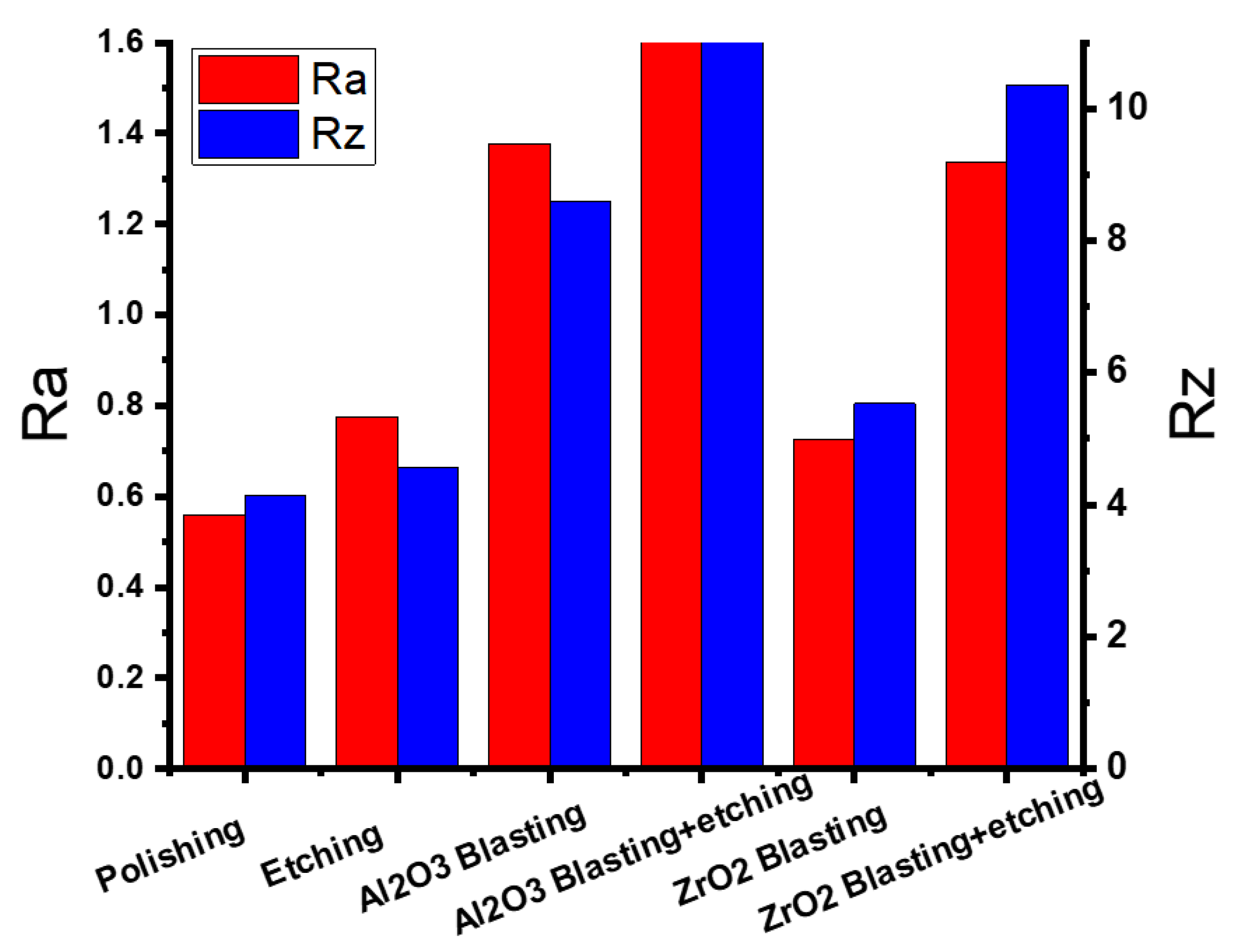
The as-polished 3D-printed sample had Ra and Rz values of 0.559 and 4.149 μm, respectively. Etching with HF, blasting with Al2O3, blasting with Al2O3 and etching, blasting with ZrO2, and blasting with ZrO2 and etching, increased Ra and Rz to 0.776 and 4.561 μm, 1.377 and 8.594 μm, 2.043 and 11.742 μm, 0.726 and 5.533 μm, and 1.336 and 10.353 μm, respectively, as shown in Figure 9. Figure 10a–d highlights the corresponding SEM micrographs after blasting with ZrO2, blasting with ZrO2 and etching, blasting with Al2O3, and blasting with Al2O3 and etching. It was noted that Figure 10d appears rougher because there are more valleys and cavities on the surface. Figure 11 shows the roughness profile difference between each condition. The absolute difference between the roughness profile of blasting with Al2O3 and etching (Figure 11d) and other samples (Figure 11a–c) was the surface topography, consisting of deep valleys (6 μm) and sharp peaks (6 μm). These results show that the surface modification process (blasting with Al2O3 and etching) is a suitable process to obtain the highest surface roughness of the produced titanium alloys. Furthermore, this surface roughness is described as a hierarchical structure composed of three different types of surface roughness based on dimensions: macro-rough (10–30 µm), micro-rough (1–10 µm), and nano-rough (less than 1 µm), all of which are advantageous to the osseointegration process [18].

4. Conclusions

The effects of surface modifications on the surface roughness of Ti6Al4V alloy components produced by 3D printing, casting, and wrought have been studied in detail. The following conclusions can be drawn from the results.
  • Significant differences were found in the surface roughness of specimens produced by 3D printing compared to those produced by casting and wrought after surface modifications were performed. This can be attributed to the difference in the surface properties of the manufactured samples, which leads to different inclusion of ejected particles on the surface of the samples.
  • The highest outcomes were collected for Ti6Al4V alloys fabricated using SLM and blasting with Al2O3, followed by HF etching (Ra = 2.043, Rz = 11.742 µm), or with Ti6Al4V fabricated using wrought and blasting with ZrO2, followed by HF etching (Ra = 1.631, Rz = 10.953 µm).
  • The surface roughness of the SLM-fabricated samples and blasting with Al2O3 or ZrO2 was considerably influenced by HF etching. In the case of the specimens with Al2O3 blasting + HF etching, the surface roughness increased from (Ra = 1.337, Rz = 8.594 µm) to (Ra = 2.043, Rz = 11.742 µm). For the specimens of ZrO2 blasting + HF etching, the surface roughness increased from (Ra = 0.726, Rz = 5.533 µm) to (Ra = 1.336, Rz = 10.353 µm).

Author Contributions

Conceptualization, J.K. and H.J.; methodology, H.H.; validation, H.H. and T.A.K.; formal analysis, T.A.K.; investigation, J.K.; data curation, J.K. and P.P.; writing—original draft preparation, H.J.; writing—review and editing, T.A.K.; visualization, J.K.; supervision, H.H. and P.P.; project administration, T.A.K. All authors have read and agreed to the published version of the manuscript.

Funding

The research was supported by the NKFIH from the project ‘Research on the health application of artificial intelligence, digital imaging, employment and material technology developments by linking the scientific results of Széchenyi István University and Semmelweis University’ under grant number TKP2021-EGA-21.

Institutional Review Board Statement

Not applicable.

Informed Consent Statement

Not applicable.

Data Availability Statement

The data used for the research are available upon request.

Acknowledgments

The authors acknowledge the support by the NKFIH from the project ‘Research on the health application of artificial intelligence, digital imaging, employment and material technology developments by linking the scientific results of Széchenyi István University and Semmelweis University’ under grant number TKP2021-EGA-21. The authors would like to express their gratitude to Dent-Arc Technik Ltd. for the technical support.

Conflicts of Interest

The authors declare no conflict of interest.

References

  1. Jaber, H.; Kovacs, T. Selective laser melting of Ti alloys and hydroxyapatite for tissue engineering: Progress and challenges. Mater. Res. Express 2019, 6, 082003. [Google Scholar] [CrossRef]
  2. Jemat, A.; Ghazali, M.J.; Razali, M.; Otsuka, Y. Surface Modifications and Their Effects on Titanium Dental Implants. BioMed Res. Int. 2015, 2015, 791725. [Google Scholar] [CrossRef] [PubMed]
  3. Monetta, T.; Bellucci, F. The effect of sand-blasting and hydrofluoric acid etching on Ti CP2 and Ti CP4 surface topography. Open J. Regen. Med. 2012, 1, 41–50. [Google Scholar] [CrossRef]
  4. Li, J.; Zhou, P.; Attarilar, S.; Shi, H. Innovative Surface Modification Procedures to Achieve Micro/Nano-Graded Ti-Based Biomedical Alloys and Implants. Coatings 2021, 11, 647. [Google Scholar] [CrossRef]
  5. Liu, X.; Chu, P.K.; Ding, C. Surface modification of titanium, titanium alloys, and related materials for biomedical applications. Mater. Sci. Eng. R Rep. 2004, 47, 49–121. [Google Scholar] [CrossRef]
  6. Souza, J.G.S.; Bertolini, M.; Costa, R.C.; Lima, C.V.; Barão, V.A.R. Proteomic profile of the saliva and plasma protein layer adsorbed on Ti–Zr alloy: The effect of sandblasted and acid-etched surface treatment. Biofouling 2020, 36, 428–441. [Google Scholar] [CrossRef] [PubMed]
  7. Wang, P.; Sin, W.J.; Nai, M.L.S.; Wei, J. Effects of Processing Parameters on Surface Roughness of Additive Manufactured Ti-6Al-4V via Electron Beam Melting. Materials 2017, 10, 1121. [Google Scholar] [CrossRef] [PubMed]
  8. Szymczyk-Ziółkowska, P.; Hoppe, V.; Rusińska, M.; Gąsiorek, J.; Ziółkowski, G.; Dydak, K.; Czajkowska, J.; Junka, A. The Impact of EBM-Manufactured Ti6Al4V ELI Alloy Surface Modifications on Cytotoxicity toward Eukaryotic Cells and Microbial Biofilm Formation. Materials 2020, 13, 2822. [Google Scholar] [CrossRef] [PubMed]
  9. Jaber, H.; Kónya, J.; Kovács, T.A. Selective Laser Melting of Ti6Al4V-2%Hydroxyapatite Composites: Manufacturing Behavior and Microstructure Evolution. Metals 2021, 11, 1295. [Google Scholar] [CrossRef]
  10. Jaber, H.; Kónya, J.; Kulcsár, K.; Kovács, T. Effects of Annealing and Solution Treatments on the Microstructure and Mechanical Properties of Ti6Al4V Manufactured by Selective Laser Melting. Materials 2022, 15, 1978. [Google Scholar] [CrossRef] [PubMed]
  11. Jaber, H.; Kovacs, T.; János, K. Investigating the impact of a selective laser melting process on Ti6Al4V alloy hybrid powders with spherical and irregular shapes. Adv. Mater. Process. Technol. 2020, 8, 715–731. [Google Scholar] [CrossRef]
  12. ASTM Standard B348/B348M; Standard Specification for Titanium and Titanium Alloy Bars and Billets. ASTM International: West Conshohocken, PA, USA, 2019; pp. 1–5. [CrossRef]
  13. Ferraris, S.; Spriano, S.; Pan, G.; Venturello, A.; Bianchi, C.L.; Chiesa, R.; Faga, M.G.; Maina, G.; Verné, E. Surface modification of Ti–6Al–4V alloy for biomineralization and specific biological response: Part I, inorganic modification. J. Mater. Sci. Mater. Med. 2011, 22, 533–545. [Google Scholar] [CrossRef] [PubMed]
  14. Da Rocha, S.S.; Adabo, G.L.; Henriques, G.E.P.; Nóbilo, M.A.D.A. Vickers hardness of cast commercially pure titanium and Ti-6Al-4V alloy submitted to heat treatments. Braz. Dent. J. 2006, 17, 126–129. [Google Scholar] [CrossRef] [PubMed]
  15. Shunmugavel, M.; Polishetty, A.; Goldberg, M.; Singh, R.; Littlefair, G. A comparative study of mechanical properties and machinability of wrought and additive manufactured (selective laser melting) titanium alloy—Ti-6Al-4V. Rapid Prototyp. J. 2017, 23, 1051–1056. [Google Scholar] [CrossRef]
  16. Reshadi, F.; Khorasani, S.; Faraji, G. Surface characterization of nanostructured commercially pure titanium modified by sandblasting and acid-etching for implant applications. Proc. Inst. Mech. Eng. Part J J. Eng. Tribol. 2019, 234, 414–423. [Google Scholar] [CrossRef]
  17. Demirci, S.; Dikici, T.; Güllüoğlu, A.N. Micro/Nanoscale Surface Modification of Ti6Al4V Alloy for Implant Applications. J. Mater. Eng. Perform. 2021, 31, 1503–1511. [Google Scholar] [CrossRef]
  18. Souza, J.C.M.; Sordi, M.B.; Kanazawa, M.; Ravindran, S.; Henriques, B.; Silva, F.S.; Aparicio, C.; Cooper, L.F. Nano-scale modification of titanium implant surfaces to enhance osseointegration. Acta Biomater. 2019, 94, 112–131. [Google Scholar] [CrossRef] [PubMed]
Figure 1. (a) 3D-printed, (b) Casting, and (c) wrought specimens.
Materials 16 03989 g001
Figure 2. SEM micrograph shows the morphology of Ti6Al4V powder.
Materials 16 03989 g002
Figure 3. Results of the surface roughness of the cast-polished and surface-modified specimens.
Materials 16 03989 g003
Figure 4. Surface roughness profile for each condition of the cast specimen. (a) Blasting with Al2O3 and etching with HF, (b) blasting with Al2O3, (c) blasting with ZrO2 and etching with HF, and (d) blasting with ZrO2.
Materials 16 03989 g004
Figure 5. SEM micrographs for each condition of the cast specimen. (a) Blasting with ZrO2, (b) blasting with ZrO2 and etching with HF, (c) blasting with Al2O3, and (d) blasting with Al2O3 and etching with HF.
Materials 16 03989 g005
Figure 6. Results of the surface roughness of the wrought-polished and surface-modified specimens.
Materials 16 03989 g006
Figure 7. SEM micrographs for each condition of the wrought specimen. (a) Blasting with ZrO2, (b) blasting with ZrO2 and etching with HF, (c) blasting with Al2O3, and (d) blasting with Al2O3 and etching with HF.
Materials 16 03989 g007
Figure 8. Surface roughness profile for each condition of the wrought specimen. (a) Blasting with ZrO2, (b) blasting with ZrO2 and etching with HF, (c) blasting with Al2O3, and (d) blasting with Al2O3 and etching with HF.
Materials 16 03989 g008
Figure 9. Results of the surface roughness of the 3D-polished and surface-modified specimens.
Materials 16 03989 g009
Figure 10. SEM micrographs for each condition of the 3D specimen. (a) Blasting with ZrO2, (b) blasting with ZrO2 and etching with HF, (c) blasting with Al2O3, and (d) blasting with Al2O3 and etching with HF.
Materials 16 03989 g010
Figure 11. Surface roughness profile for each condition of the SLM specimen. (a) Blasting with ZrO2, (b) blasting with ZrO2 and etching with HF, (c) blasting with Al2O3, and (d) blasting with Al2O3 and etching with HF.
Materials 16 03989 g011
Table 1. Chemical analysis of Ti64 powder and ASTM specification.
(Mass%)AlVFeONCHTi
Ti6Al4V powder6.114.020.170.0900.0230.010.003Bal
ASTM B348 Gr.23 [12]Max6.754.500.400.200.050.080.015Bal
Min5.503.50------
Table 2. The Ra and Rz values of the surface of the Ti6Al4V alloys manufactured by 3D printing, casting, and wrought after surface modifications.
Production TechnologySurface TreatmentSurface Roughness, Ra (μm)Roughness Height, Rz (μm)
Specimen NumberAverageSpecimen NumberAverage
123123
CastingPolishing0.4790.5310.4990.5033.3973.5063.8163.573
CastingEtching0.3120.3530.3670.3442.3172.8892.9642.723
CastingAl2O3 Blasting1.2081.1401.3601.2369.3297.4828.2658.359
CastingAl2O3 Blasting + etching1.4231.4681.5081.46611.7038.0008.5809.428
CastingZrO2 Blasting0.7341.0490.9160.9007.4999.7776.4177.898
CastingZrO2 Blasting + etching0.8041.3071.0611.0758.1989.8438.6708.904
WroughtPolishing0.3600.4750.5550.4632.4973.0833.6793.086
WroughtEtching0.3320.4990.5560.4622.4163.3103.6103.112
WroughtAl2O3 Blasting0.4930.6340.8230.6503.5154.4156.2224.171
WroughtAl2O3 Blasting + etching0.7290.8771.2150.9406.1445.98210.9537.693
WroughtZrO2 Blasting1.3291.4601.4151.4019.0177.9518.9658.644
WroughtZrO2 Blasting + etching1.5191.6361.7381.63110.00110.46212.39710.953
3D printingPolishing0.4740.7010.5020.5594.0794.9153.45164.149
3D printingEtching0.7550.9950.5790.7764.7875.9742.9234.561
3D printingAl2O3 Blasting1.3281.2391.4441.3779.0917.5079.1838.594
3D printingAl2O3 Blasting + etching2.6231.7631.7432.04312.62511.25211.34911.742
3D printingZrO2 Blasting0.7150.6770.7860.7266.1035.0245.4735.533
3D printingZrO2 Blasting + etching1.5491.5570.9031.33611.61812.6936.74810.353
Disclaimer/Publisher’s Note: The statements, opinions and data contained in all publications are solely those of the individual author(s) and contributor(s) and not of MDPI and/or the editor(s). MDPI and/or the editor(s) disclaim responsibility for any injury to people or property resulting from any ideas, methods, instructions or products referred to in the content.