
Effects of Surface Properties of Fiber on Interface Properties of Carbon Fiber/Epoxy Resin and Its Graphene Oxide Modified Hybrid Composites
Abstract
:1. Introduction
2. Experiments
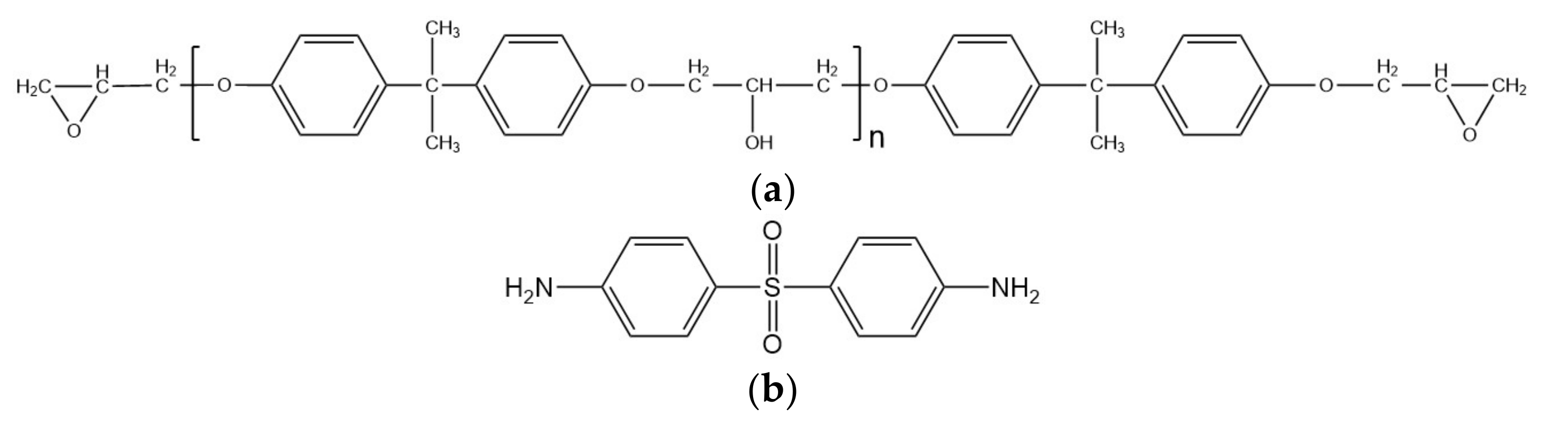
2.1. Materials
2.2. Methods
2.3. Characterization
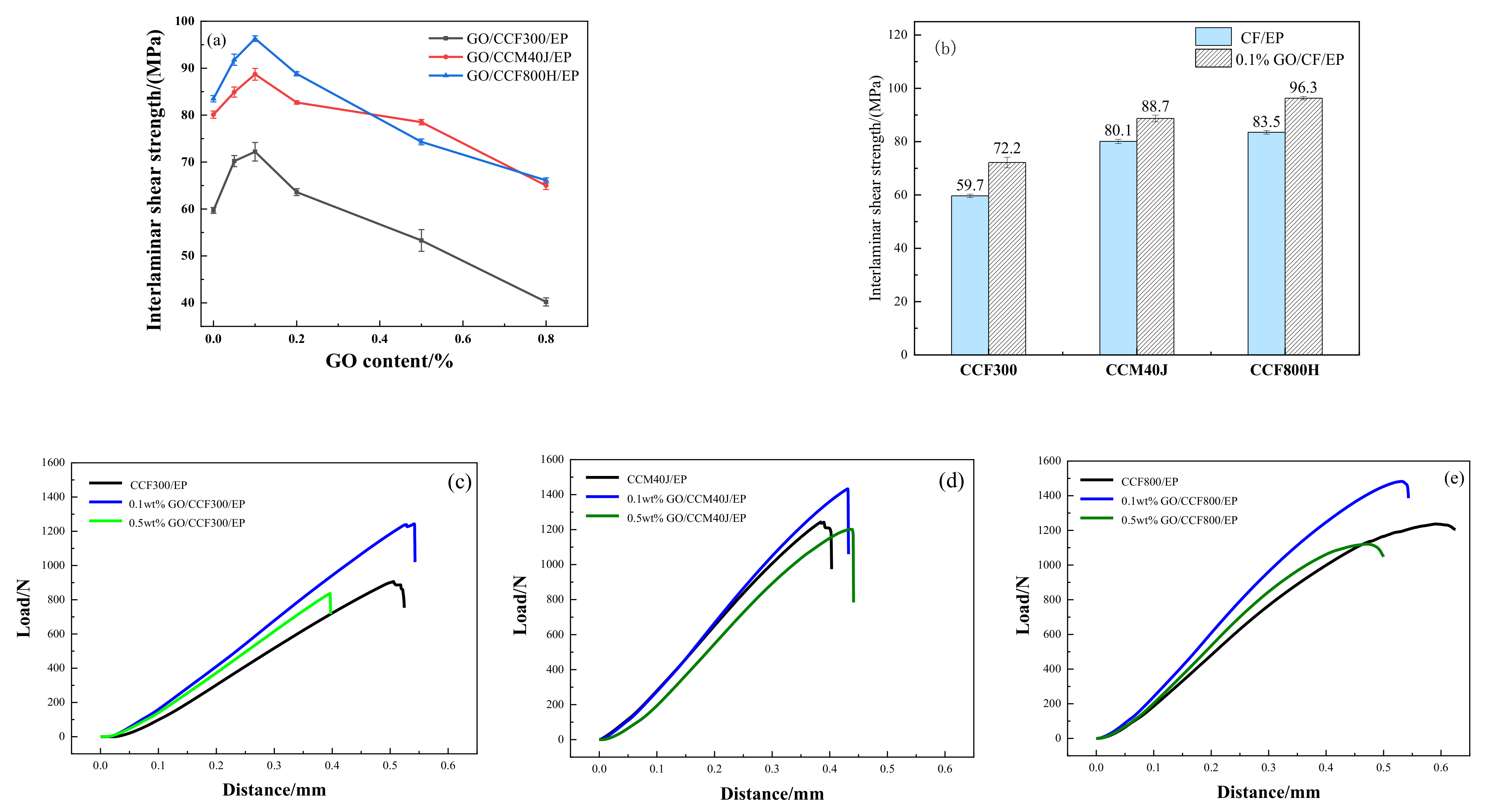
3. Results
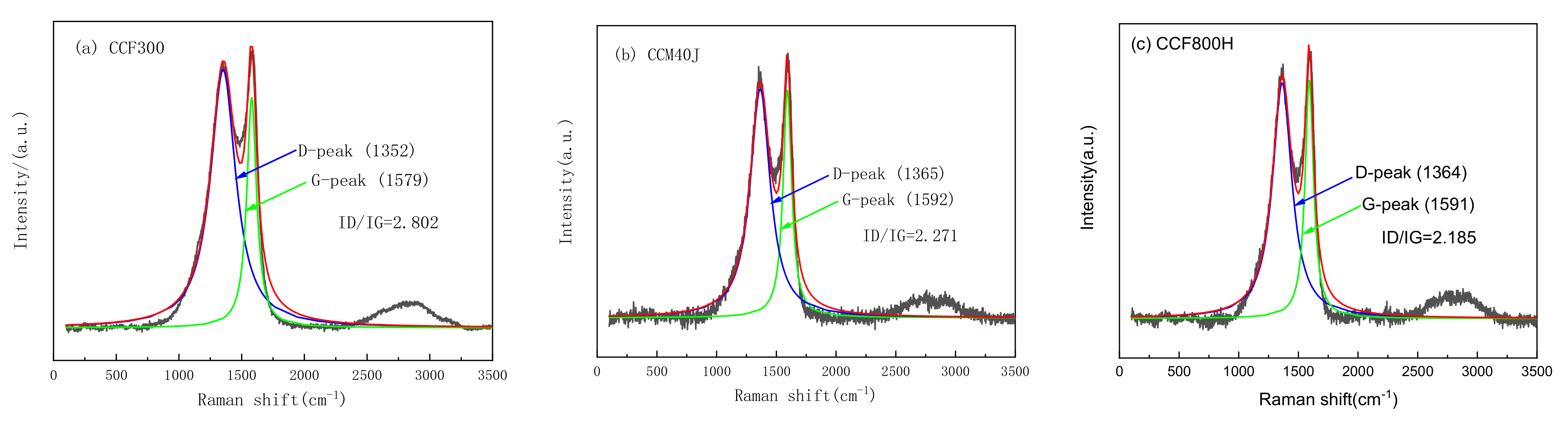
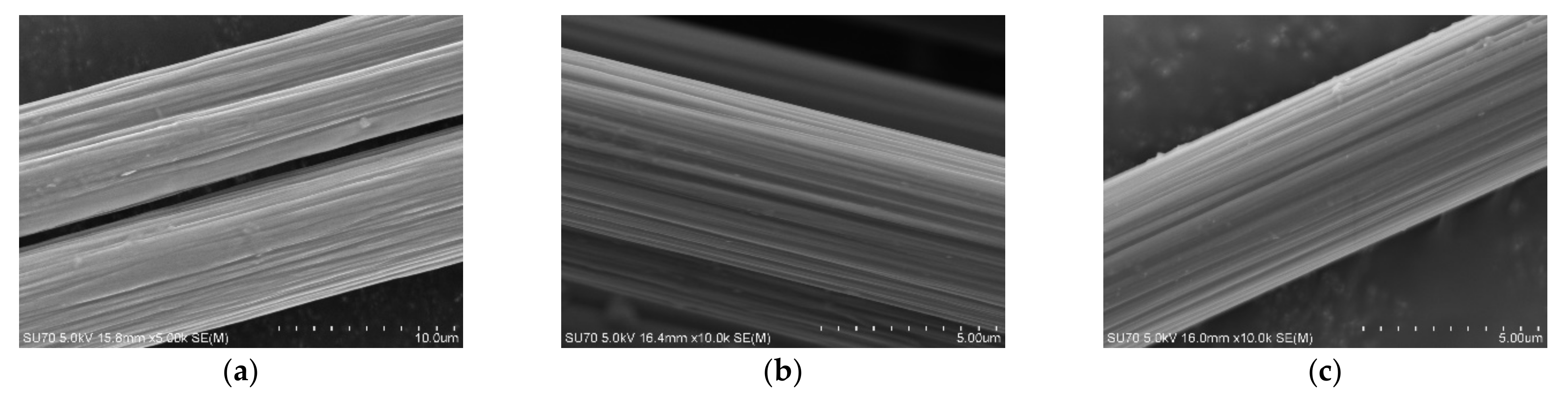
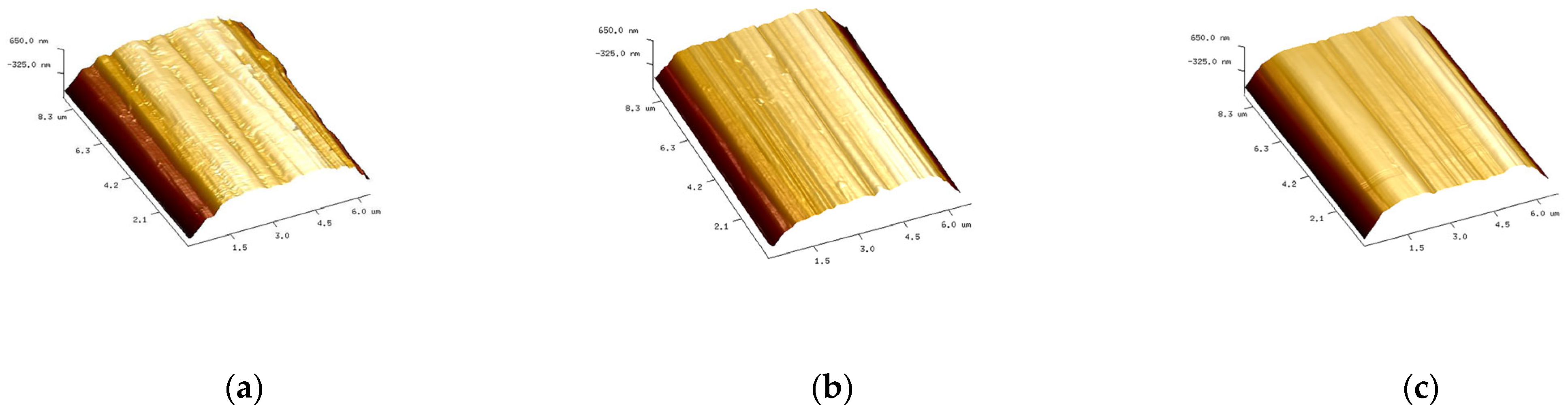
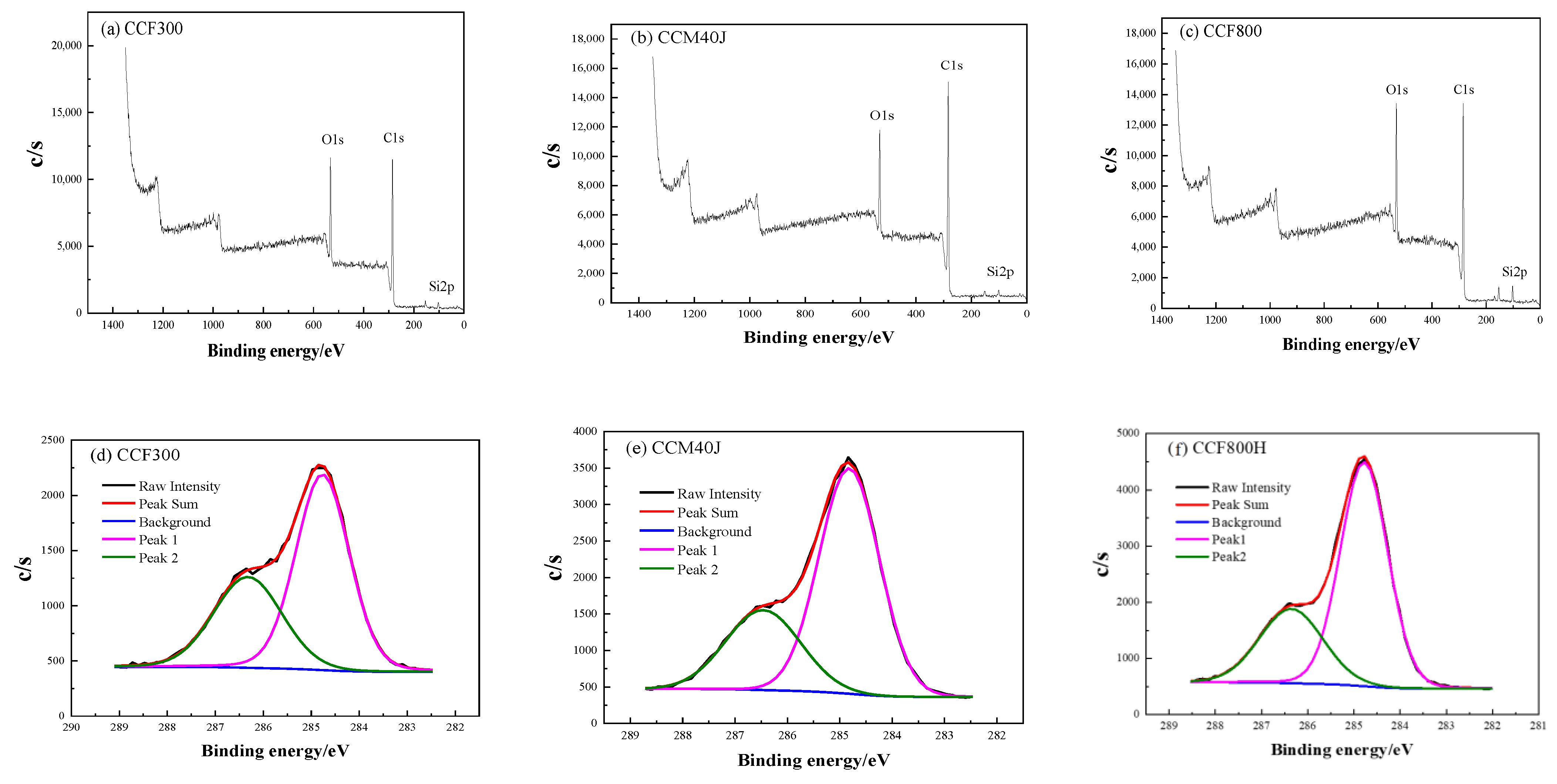
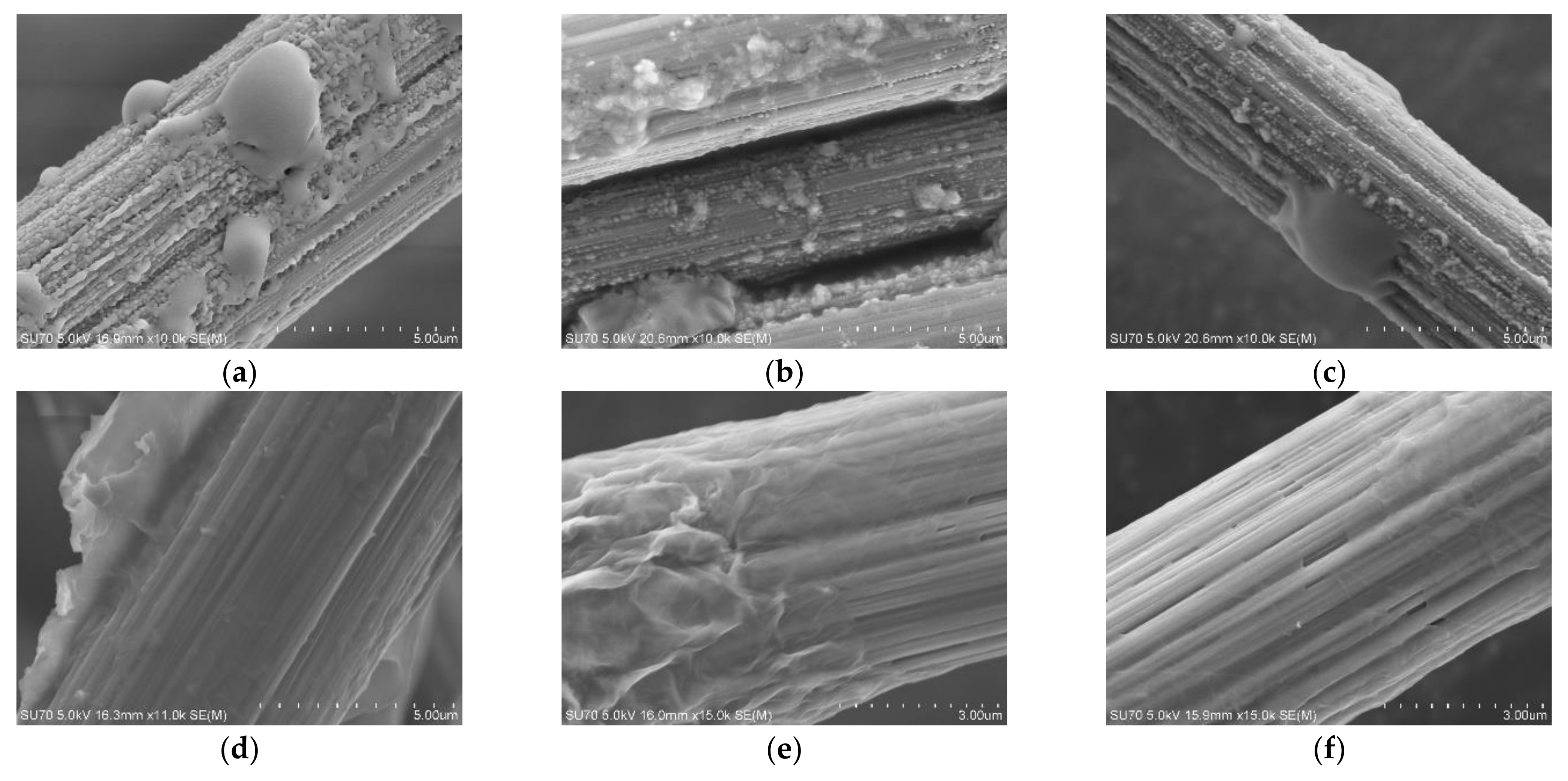
3.1. Carbon Fiber CCF300, CCF800H and CCM40J
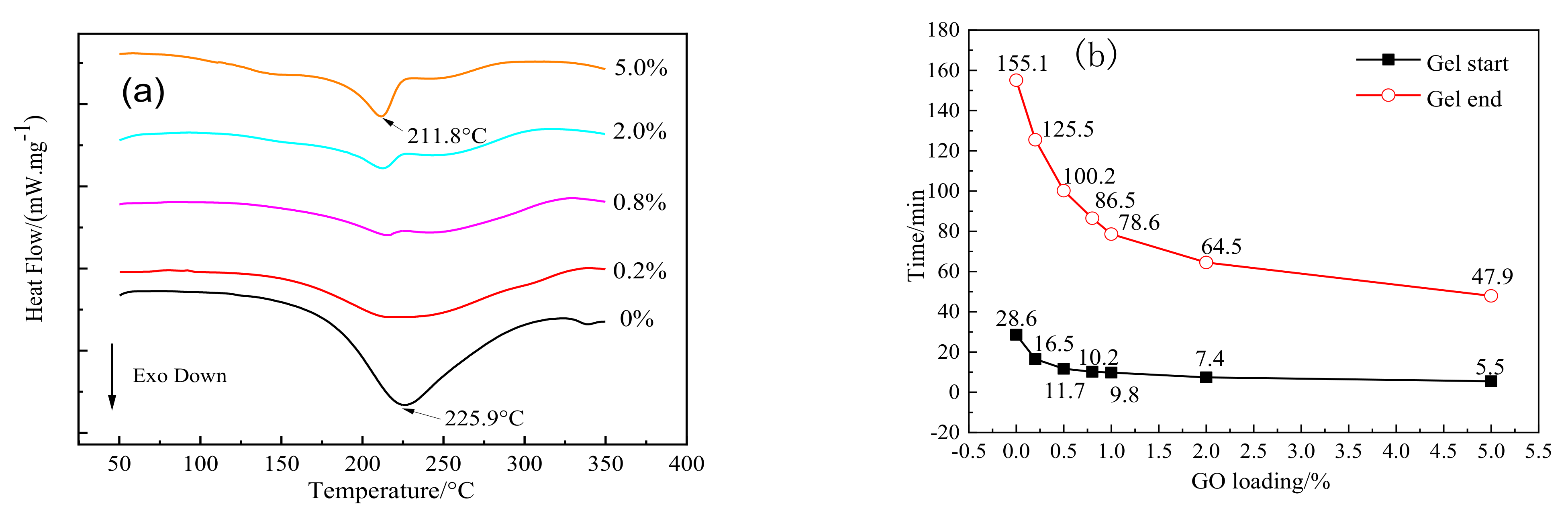
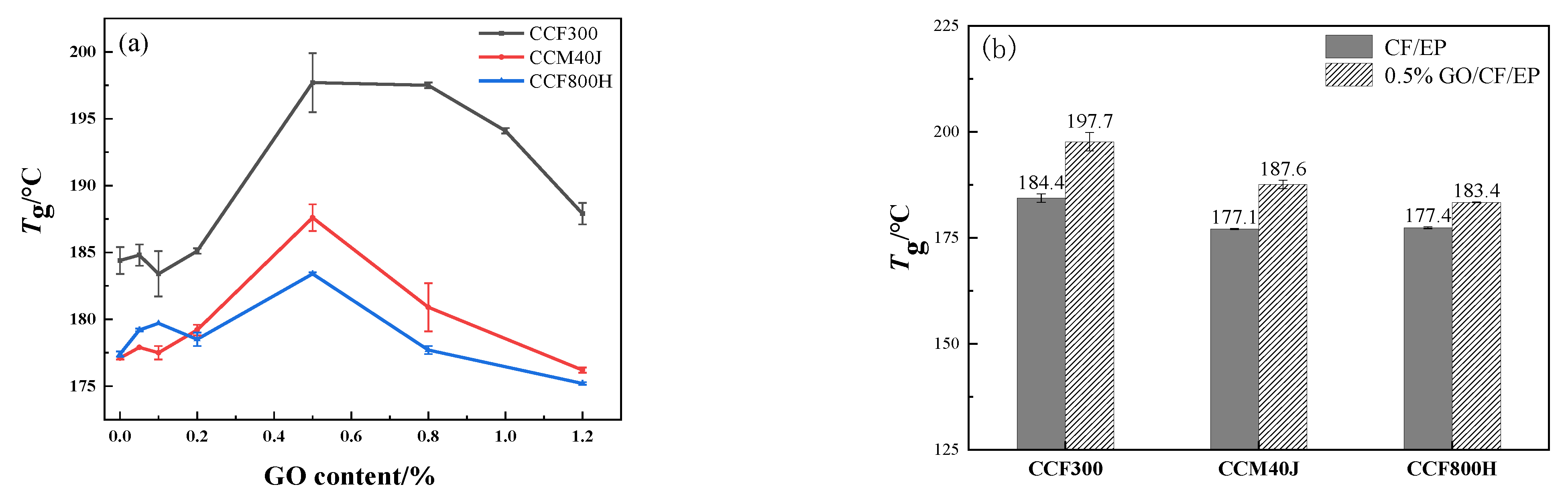
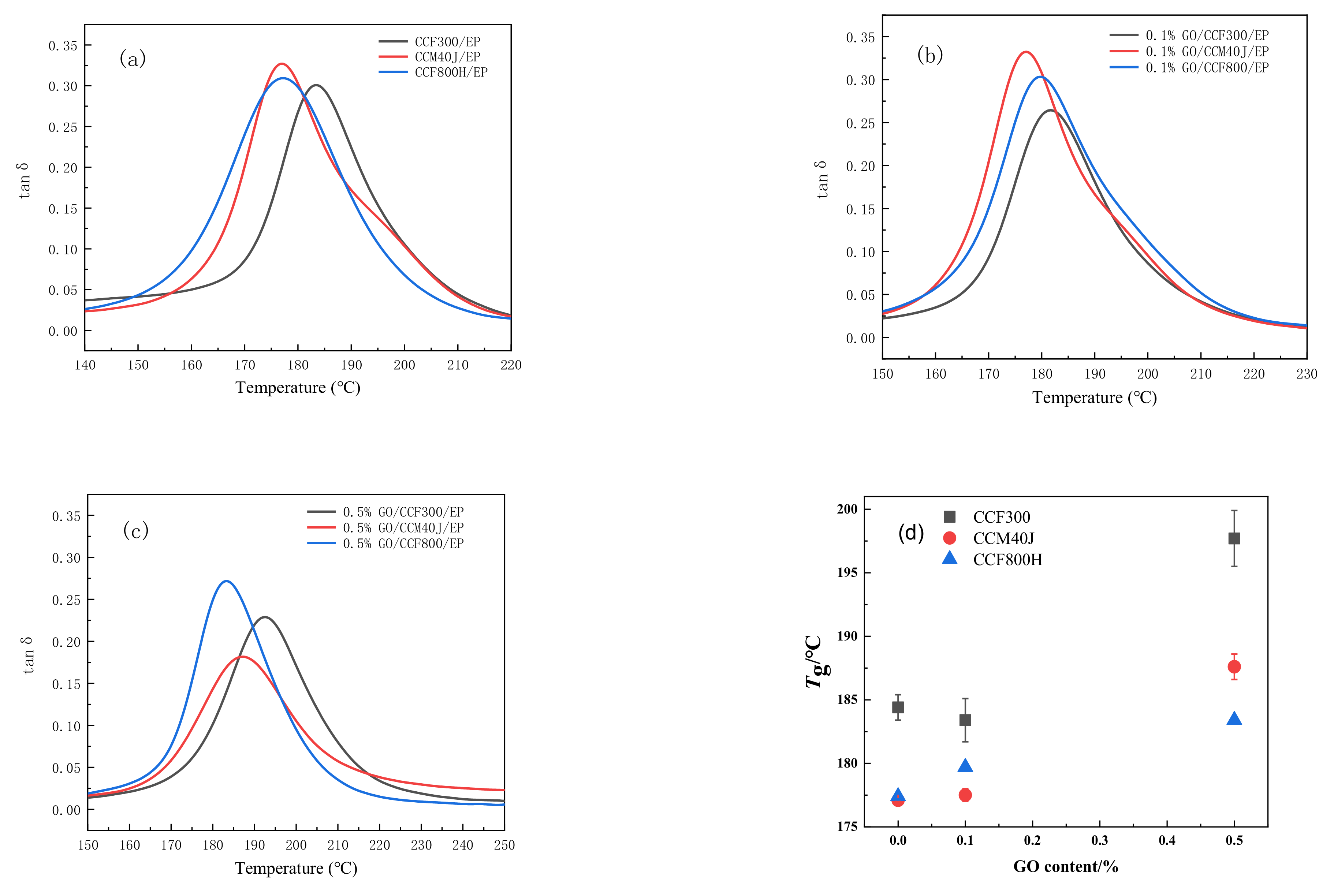
3.2. Dynamic Thermomechanical Properties
4. Conclusions
Author Contributions
Funding
Institutional Review Board Statement
Informed Consent Statement
Data Availability Statement
Conflicts of Interest
References
- Chand, S.J. Review carbon fibers for composites. J. Mater. Sci. 2000, 35, 1303–1313. [Google Scholar] [CrossRef]
- Du, S.Y. Advanced composite materials and aerospace engineering. Acta Mater. Compos. Sin. 2007, 24, 1–12. (In Chinese) [Google Scholar]
- Betzler, N.F.; Slater, C.; Strangwood, M.; Monk, S.A.; Otto, S.R.; Wallace, E.S. The static and dynamic stiffness behavior of composite golf shafts and their constituent materials. Sports Eng. 2011, 14, 27–37. [Google Scholar] [CrossRef]
- Li, Y.B.; Peng, Q.Y.; He, X.D.; Hu, P.; Wang, C.; Shang, Y.S.; Wang, R.G.; Lv, H.Z. Synthesis and characterization of a new hierarchical reinforcement by chemically grafting graphene oxide onto carbon fibers. J. Mater. Chem. 2012, 22, 18748–18752. [Google Scholar] [CrossRef]
- Zheng, N.; He, J.M.; Zhao, D.; Huang, Y.D.; Gao, J.F.; Mai, Y.W. Improvement of atomic oxygen erosion resistance of carbon fiber and carbon fiber/epoxy composite interface with a silane coupling agent. Mater. Des. 2016, 109, 171–178. [Google Scholar] [CrossRef]
- Jiang, J.J.; Yao, X.M.; Xu, C.M.; Su, Y.; Zhou, L.C.; Deng, C. Influence of electrochemical oxidation of carbon fiber on the mechanical properties of carbon fiber/graphene oxide/epoxy composites. Composites Part A 2017, 95, 248–256. [Google Scholar] [CrossRef]
- Zhang, K.L.; Li, Y.J.; He, X.W.; Nie, M.; Wang, Q. Mechanical interlock effect between polypropylene/carbon fiber composite generated by interfacial branched fibers. Compos. Sci. Technol. 2018, 167, 1–6. [Google Scholar] [CrossRef]
- Markandan, K.; Kanaujia, P.K.; Abhineet, J.P.; Yap, X.Y.; Gan, C.L.; Lai, C.Q. Improvements in the modulus and strength of multi-dimensional hybrid composites through synergistic reinforcement between 1D fiber and 0D particle fillers. J. Mater. Sci. 2021, 56, 15162–15179. [Google Scholar] [CrossRef]
- Lee, D.W.; de Los Santos, L.V.; Seo, J.W.; Felix, L.L.; Bustamante, D.A.; Cole, J.M.; Barnes, C.H. The structure of graphite oxide: Investigation of its surface chemical groups. J. Phys. Chem. B 2010, 114, 5723–5728. [Google Scholar] [CrossRef]
- Spitalsky, Z.; Danko, M.; Mosnacek, J. Preparation of functionalized graphene sheets. Curr. Org. Chem. 2011, 15, 1133–1150. [Google Scholar] [CrossRef]
- Zhang, M.M.; Yan, H.X.; Gong, C.; Zhang, F.F. Hyperbranched polysiloxane functionalization of graphene oxide for improved mechanical properties of cyanate ester nanocomposites. J. Compos. Mater. 2014, 49, 939–948. [Google Scholar] [CrossRef]
- Xu, P.J.; Cong, P.L.; Gao, Z.; Du, M.; Wang, Z.P.; Su, X.; Zhao, X.Q. High performance graphene oxide-modified polybenzoxazine resin. Polym. Compos. 2016, 37, 1507–1514. [Google Scholar] [CrossRef]
- Wang, D.; Gao, J.; Xu, W.F.; Bao, F. The synthesis and characterization of the graphene oxide covalent modified phenolic resin nanocomposites. Adv. Mater. Res. 2011, 327, 115–119. [Google Scholar] [CrossRef]
- Pathak, A.K.; Borah, M.; Gupta, A.; Yokozeki, T.; Dhakate, S.R. Improved mechanical properties of carbon fiber/graphene oxide-epoxy hybrid composites. Compos. Sci. Technol. 2016, 135, 28–38. [Google Scholar] [CrossRef]
- Zhang, X.Q.; Fan, X.Y.; Yan, C.; Li, H.Z.; Zhu, Y.D.; Li, X.T. Interfacial microstructure and properties of carbon fiber composites modified with graphene oxide. ACS Appl. Mater. Interfaces 2012, 4, 1543–1552. [Google Scholar] [CrossRef] [PubMed]
- Adak, N.C.; Chhetri, S.; Murmu, N.C.; Samanta, P.; Kuila, T. Effect of thermally reduced graphene oxide on mechanical properties of woven carbon fiber/epoxy composite. Crystals 2018, 8, 111. [Google Scholar] [CrossRef]
- Fu, H.M.; Yang, Y.S.; Zhang, Y.B. Failure mode research on CCF300and T300composites under tensile strength. J. Aerospace Power 2010, 25, 2163–2169. (In Chinese) [Google Scholar]
- Xu, Y.X.; Gu, Y.Z.; Ma, Q.S.; Li, M.; Wang, S.K.; Zhang, Z.G. Experimental analysis of characteristics of several domestic high modulus carbon fibers. Acta Mater. Compos. Sin. 2016, 33, 1905–1914. (In Chinese) [Google Scholar]
- He, D.N.; Li, J.W.; Huang, J.J.; Xu, M.R. Influence of Defect Types and Sizes on Compressive Properties of 3238A /CCF800 Composite Laminates. Eng. Test 2020, 60, 18–21. (In Chinese) [Google Scholar]
- Luo, Y.; Zhao, Y.; Duan, Y.; Du, S. Surface and wettability property analysis of CCF300 carbon fibers with different sizing or without sizing. Mater. Des. 2011, 32, 941–946. [Google Scholar] [CrossRef]
- Hummers, W.S.; Offeman, R.E. Preparation of graphitic oxide. JACS 1958, 208, 1334–1339. [Google Scholar] [CrossRef]
- ASTM D7028-07e1; Standard Test Method for Glass Transition Temperature (DMA Tg) of Polymer Matrix Composites by Dynamic Mechanical Analysis (DMA). American Society for Testing and Materials: West Conshohocken, PA, USA, 2007.
- Xie, J.H.; Yang, S.C.; Shen, Z.; Li, X.Q. Test Method for Short-Beam Shear Strength of Polymer Matrix Composite Materials: GBT 30969-2014; China Standards Press: Beijing, China, 2014. (In Chinese) [Google Scholar]
- Han, Z.; Zhang, X.J.; Tian, Y.H.; Yang, Y.F.; Shen, Z.M. Effect of graphitization temperature on microstructure of PAN-based high modulus graphite fibers. Chem. Ind. Eng. Prog. 2011, 30, 1805–1808. (In Chinese) [Google Scholar]
- Liu, F.J.; Wang, H.J.; Fan, L.D.; Zhu, Z.P. Analysis on the microstructure of MJ series carbon fibers. New Chem. Mater. 2009, 37, 41–43. (In Chinese) [Google Scholar]
- Zhong, Y.J.; Bian, W.F. Analysis of the tensile moduli affected by microstructures among seven types of carbon fibers. Composites Part B 2017, 110, 178–184. [Google Scholar] [CrossRef]
- Li, Y.; Zhao, Y.; Liu, G.; Li, S.X.; Li, L.; Li, L. Properties of domestic CCF300 carbon fiber and its NCF fabric. Acta Aeronaut. Astronaut. Sin. 2014, 35, 2889–2900. (In Chinese) [Google Scholar]
- Zhong, X.Y.; Zhang, D.J.; Bao, J.W.; Li, W.D. Influence of Content of Toughening Thermoplastic on Mode-Ⅰ Interlaminar Fracture Toughness of Epoxy Composite Reinforced by CCF800H Carbon Fiber. J. Mater. Eng. 2017, 45, 55–61. (In Chinese) [Google Scholar]
- Zhang, D.D.; Yang, Y.G.; Tan, S.P.; Gao, J.J.; Ye, S.C.; Xue, F. Effect of the surface status of carbon fiber on the properties of its composite with epoxy resin. New Chem. Mater. 2014, 42, 73–76. (In Chinese) [Google Scholar]
- Dreyer, D.R.; Park, S.; Bielawski, C.W.; Ruoff, R.S. The chemistry of graphene oxide. Chem. Soc. Rev. 2009, 39, 228–240. [Google Scholar] [CrossRef]
- Markandan, K.; Seetoh, I.P.; Lai, C.Q. Mechanical anisotropy of graphene nanocomposites induced by graphene alignment during stereolithography 3D printing. J. Mater. Res. 2021, 36, 4262–4274. [Google Scholar] [CrossRef]
- McAllister, M.J.; Li, J.L.; Adamson, D.H.; Schniepp, H.C.; Abdala, A.A.; Liu, J.; Herrera-Alonso, M.; Milius, D.L.; Car, R.; Prudhomme, R.K.; et al. Single sheet functionalized graphene by oxidation and thermal expansion of graphite. Chem. Mater. 2007, 19, 4396–4404. [Google Scholar] [CrossRef]
- Niu, Y.A.; Zhang, Q.M.; Li, Y.; Fang, Q.H.; Zhang, X. Reduction, dispersity and electrical properties of graphene oxide sheets under low-temperature thermal treatments. J. Mater. Sci. Mater. Electron. 2017, 28, 729–733. [Google Scholar] [CrossRef]
- Qiu, S.L.; Wang, C.S.; Wang, Y.T.; Liu, C.G. Effects of graphene oxides on the cure behaviors of a tetrafunctional epoxy resin. Express Polym. Lett. 2011, 5, 809–818. [Google Scholar] [CrossRef]
- Sui, X.D.; Xiong, S.; Zhu, L.; Li, Y.; Li, N. Hygrothermal properties of domestic T800 carbon fiber/epoxy resin composites. J. Aeronaut. Mater. 2019, 39, 88–93. (In Chinese) [Google Scholar]
- Hu, G.M.; Yang, F.H.; He, H.Y.; Yi, M.Z. Microstructure and mechanical properties of CCF300-3K carbon fiber and KD-II SiC fiber. Mater. Sci. Eng. Powder Metall. 2018, 23, 26–33. (In Chinese) [Google Scholar]
- Song, W.; Gu, A.J.; Liang, G.Z.; Li, Y. Effect of the surface roughness on interfacial properties of carbon fibers reinforced epoxy resin composites. Appl. Surf. Sci. 2011, 257, 4069–4074. [Google Scholar] [CrossRef]
- Guo, M.L. Dynamic Mechanical and Thermal Analysis of Polymers and Composites; Chemical Industry Press: Beijing, China, 2002; ISBN 7-5025-3834-8. [Google Scholar]
- Ibarra, L.; David, P. Dynamic properties of thermoplastic butadiene-styrene (SBS) and oxidized short carbon fiber composite materials. J. Appl. Polym. Sci. 1998, 67, 1819–1826. [Google Scholar] [CrossRef]
- He, W.; Xing, T.; Liao, G.X.; Lin, W.; Deng, F.; Jian, X.G. Dynamic mechanical properties of PPESK/Silica hybrid materials. Polym. Plast. Technol. Eng. 2009, 48, 164–169. [Google Scholar] [CrossRef]

| Carbon Fiber | Tensile Strength /GPa | Tensile Modulus /GPa | Density /(g·cm−3) | Diameter /μm |
|---|---|---|---|---|
| CCF300 [26] | 3.90 | 220 | 1.78 | 7.0 |
| CCM40J [25] | 4.41 | 377 | 1.79 | 5.0 |
| CCF800H [27] | 5.49 | 290 | 1.81 | 5.3 |
| Carbon Fiber | C1s | O1s | Si2p | N1s | O/C Ratio |
|---|---|---|---|---|---|
| Content/% | Content/% | Content/% | Content/% | ||
| CCF300 | 72.93 | 23.24 | 3.09 | 0.74 | 0.32 |
| CCM40J | 80.93 | 15.99 | 2.27 | 0.81 | 0.20 |
| CCF800H | 76.03 | 18.16 | 4.95 | 0.86 | 0.24 |
| Carbon Fiber | Peak 1 (−C−C or −C−H) | Peak 2 (C−O) | ||
|---|---|---|---|---|
| BE/eV | Content/% | BE/eV | Content/% | |
| CCF300 | 284.8 | 63.2 | 286.3 | 36.8 |
| CCM40J | 284.8 | 69.7 | 286.5 | 30.3 |
| CCF800H | 284.8 | 69.3 | 286.4 | 30.7 |
| Sample |
|
|
|
|
|---|---|---|---|---|
| Pure EP | 181.5 | 225.9 | 274.2 | −359.5 |
| 0.2% GO-EP | 172.1 | 221.9 | 293.2 | −339.0 |
| 0.8% GO-EP | 165.1 | 215.6 | 282.8 | −191.6 |
| 2.0% GO-EP | 121.0 | 212.7 | 294.5 | −162.3 |
| 5.0% GO-EP | 112.8 | 211.8 | 285.2 | −190.4 |
Disclaimer/Publisher’s Note: The statements, opinions and data contained in all publications are solely those of the individual author(s) and contributor(s) and not of MDPI and/or the editor(s). MDPI and/or the editor(s) disclaim responsibility for any injury to people or property resulting from any ideas, methods, instructions or products referred to in the content. |
© 2023 by the authors. Licensee MDPI, Basel, Switzerland. This article is an open access article distributed under the terms and conditions of the Creative Commons Attribution (CC BY) license (https://creativecommons.org/licenses/by/4.0/).
Share and Cite
Bai, W.; Liu, W.; Li, W.; Lin, Z.; Qiu, H.; Hu, X. Effects of Surface Properties of Fiber on Interface Properties of Carbon Fiber/Epoxy Resin and Its Graphene Oxide Modified Hybrid Composites. Materials 2023, 16, 4005. https://doi.org/10.3390/ma16114005
Bai W, Liu W, Li W, Lin Z, Qiu H, Hu X. Effects of Surface Properties of Fiber on Interface Properties of Carbon Fiber/Epoxy Resin and Its Graphene Oxide Modified Hybrid Composites. Materials. 2023; 16(11):4005. https://doi.org/10.3390/ma16114005
Chicago/Turabian StyleBai, Weihua, Wenjun Liu, Weidong Li, Zewen Lin, Hong Qiu, and Xiaolan Hu. 2023. "Effects of Surface Properties of Fiber on Interface Properties of Carbon Fiber/Epoxy Resin and Its Graphene Oxide Modified Hybrid Composites" Materials 16, no. 11: 4005. https://doi.org/10.3390/ma16114005