

The Influence of Tool Geometry on the Mechanical Properties and the Microstructure of AA6061-T6 Aluminum Alloy Friction Stir Spot Welding


Abstract
:1. Introduction
2. Experimental Details
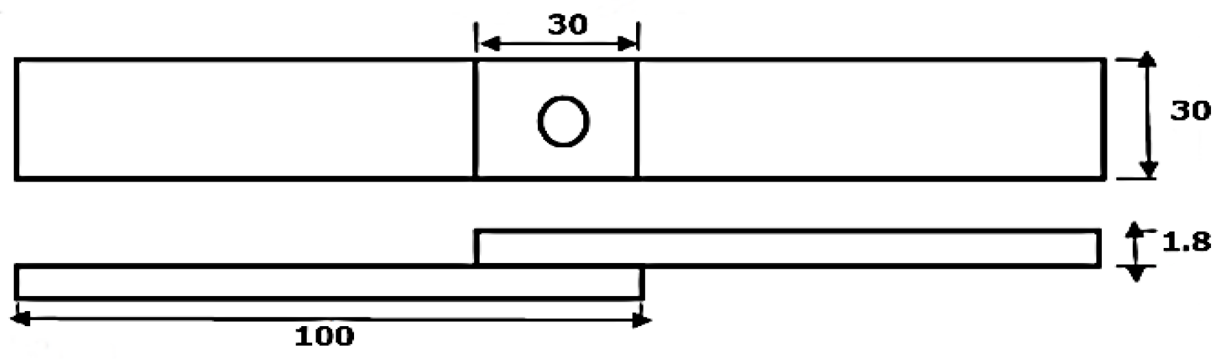
2.1. Materials
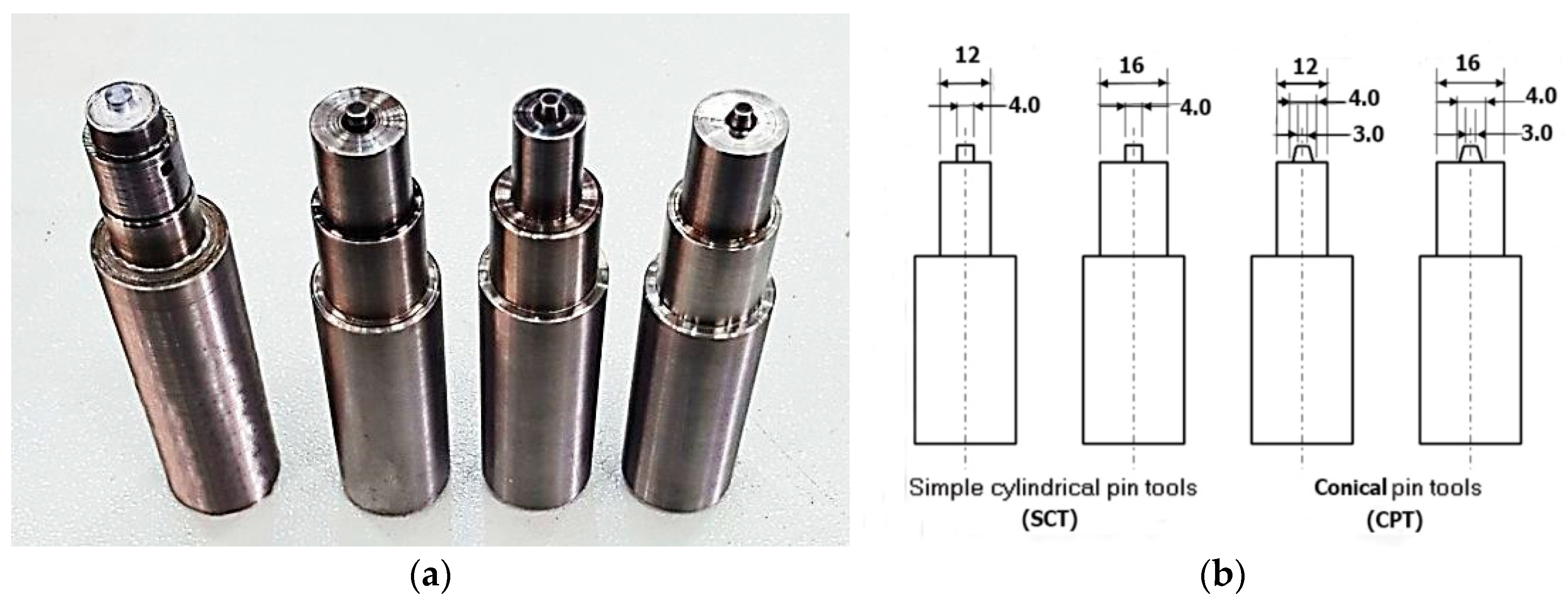
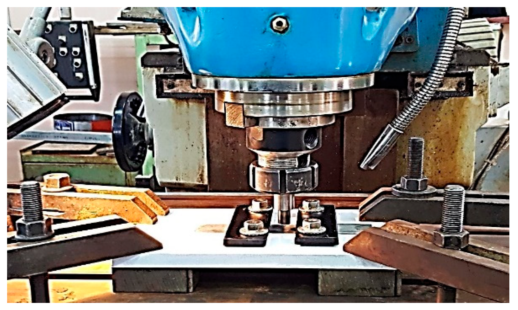
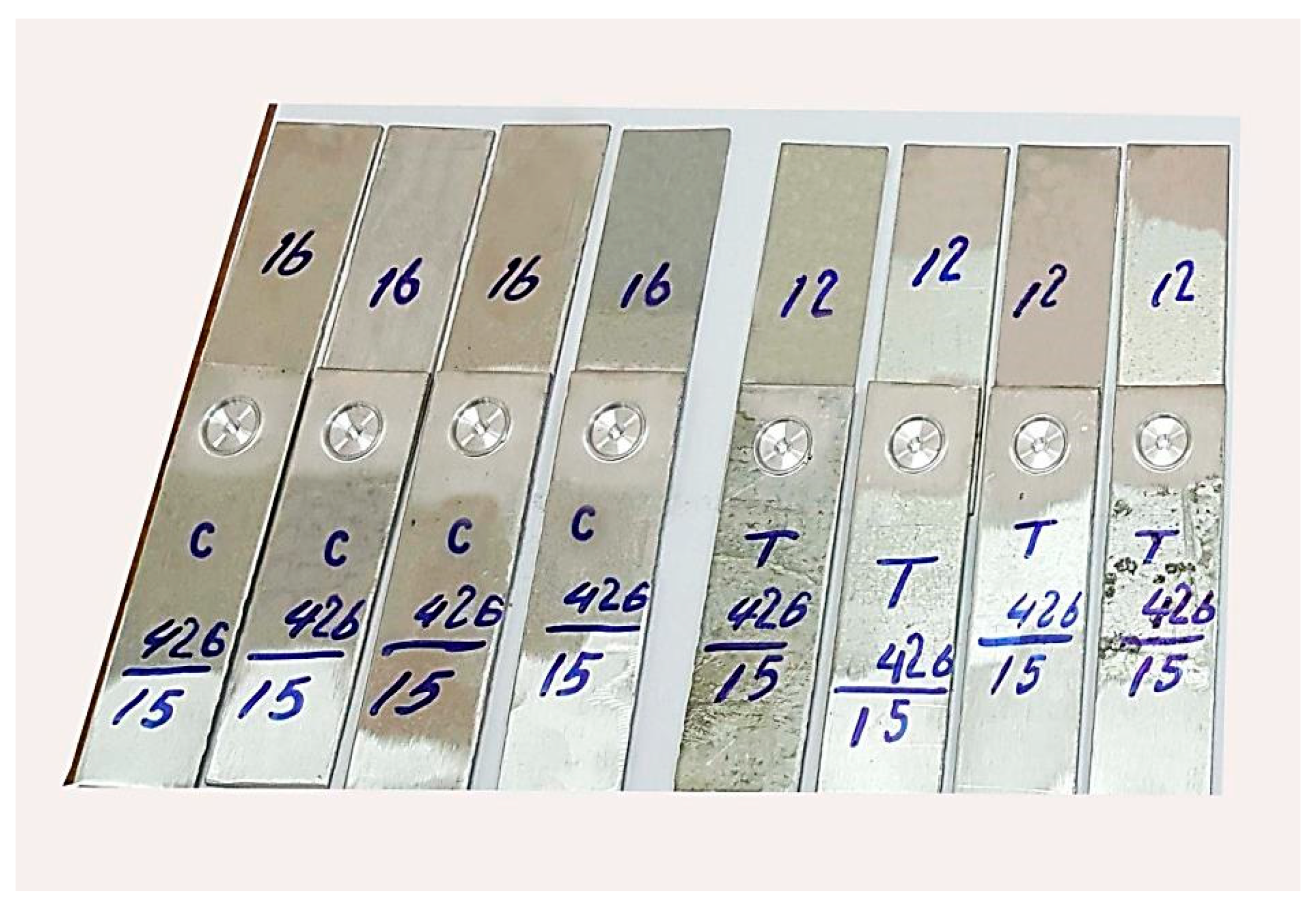
2.2. Test Procedures
3. Results and Discussion
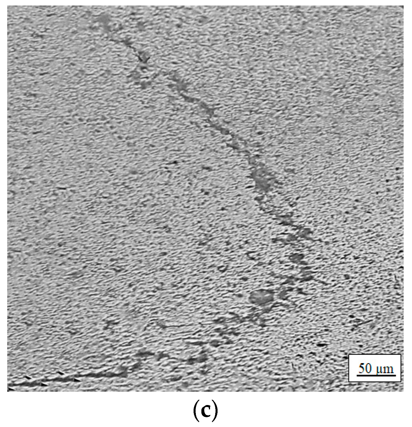
3.1. Macro and Microstructure of the Weld Region
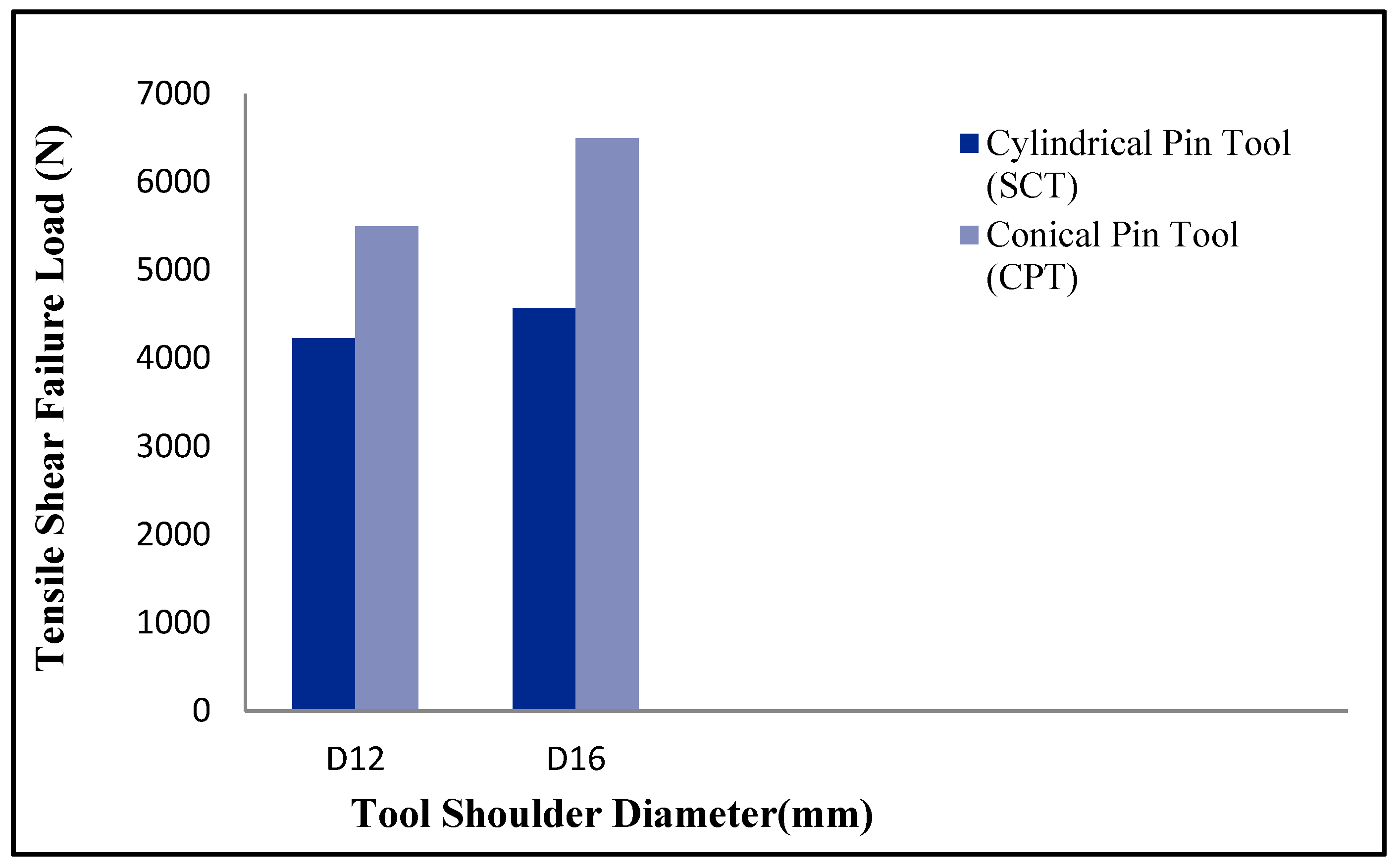
3.2. Tensile-Shear Strength
3.3. Microhardness
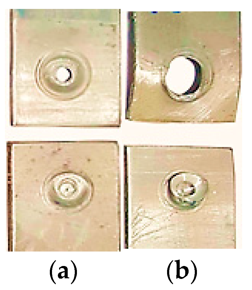
3.4. Failure Modes
4. Conclusions
- (1)
- Finer grains were observed in the SZ of the specimen formed using the 16 mm shoulder diameter and the cylindrical pin tool, compared to the specimen formed using the 12 mm shoulder diameter and conical pin tool. This result is justified by the higher frictional heat generated by the higher shoulder diameter and the higher plastic deformation produced using the cylindrical pin tool.
- (2)
- Higher tensile strength was obtained with the 16 mm shoulder diameter compared with the 12 mm diameter for the SCT and the CPT tools. An increase of about 8% in the case of the SCT and 18% in the case of the CPT were observed.
- (3)
- The experimental results reported higher TSFL with the CPT tool compared to the SCT tool. An increase of about 30% was achieved with the 12 mm tool shoulder diameter and of about 42% when the 16 mm shoulder diameter was used. This increase in TSFL can be attributed to the higher bonded area produced during the FSSW process when using the CPT tool compared to the SCT tool.
- (4)
- Higher hardness in the SZ was reported by the specimen performed with the SCT tool than other specimens performed at the same welding conditions but using the CPT tool. However, the CPT tool produced higher tensile shear strength due to the higher bonded area.
- (5)
- The tool pin profile affects the failure mode through controlling the nugget thickness and the hook geometry.
- (6)
- The FSSW specimens performed with the SCT tool fractured at a relatively lower tensile shear load with the interfacial failure mode. On the other hand, the specimens performed with the CPT tool fractured at a relatively higher tensile shear load with the circumferential failure mode.
Author Contributions
Funding
Institutional Review Board Statement
Informed Consent Statement
Data Availability Statement
Conflicts of Interest
References
- Venukumar, S.; Yalagi, S.; Muthukumaran, S. Comparison of microstructure and mechanical properties of conventional and refilled friction stir spot welds in AA 6061-T6 using filler plate. Trans. Nonferr. Met. Soc. China 2013, 23, 2833–2842. [Google Scholar] [CrossRef]
- Gerlich, A.; Su, P.; North, T.H. Peak temperatures and microstructures in aluminum and magnesium alloy friction stir spot welds. Sci. Technol. Weld. Join. 2005, 10, 647–652. [Google Scholar] [CrossRef]
- Abdul-Aziz, H.M.; Abbas, N.M.; Jasim, A.H. Artifitial Aging Time Effect on Corrosion Resistance for Friction Stir Welded AA6061 T6. Diyala J. Eng. Sci. 2013, 6, 83–96. [Google Scholar] [CrossRef]
- Mohanty, H.K.; Venkateswarlu, D.; Mahapatra, M.M.; Kumar, P.; Mandal, N.R. Modeling the effects of tool probe geometries and process parameters on friction stirred aluminum welds. J. Mech. Eng. Autom. 2012, 2, 74–79. [Google Scholar] [CrossRef]
- Bisadi, H.; Tour, M.; Tavakoli, A. The Influence of Process Parameters on Microstructure and Mechanical Properties of Friction Stir Welded Al 5083 alloy Lap joint. Am. J. Mater. Sci. 2011, 1, 93–97. [Google Scholar] [CrossRef]
- Yuan, W. Friction Stir Spot Welding of Aluminum Alloys. Master’s Thesis, Missouri University of Science and Technology, Rolla, MO, USA, 2008. [Google Scholar]
- Yang, Q.; Mironov, S.; Sato, Y.; Okamoto, K. Material flow during friction stir spot welding. Mater. Sci. Eng. A 2010, 527, 4389–4398. [Google Scholar] [CrossRef]
- Buffa, G.; Fanelli, P.; Fratini, L.; Vivio, F. Influence of Joint Geometry on Micro and Macro Mechanical Properties of Friction Stir Spot Welded Joints. Procedia Eng. 2014, 81, 2086–2091. [Google Scholar] [CrossRef]
- Davis, J.R. Aluminum and Aluminum Alloys; ASM International: Materials Park, OH, USA, 1993. [Google Scholar]
- Alheta, S.; Zayan, S.; Mahmoud, T.; Gomaa, A. Optimization of Friction Stir Spot Welding Process Parameters for AA6061-T4 Aluminum Alloy Plates. Am. Sci. Res. J. Eng. Technol. Sci. 2016, 20, 244–253. [Google Scholar]
- Nadikudi, B.K.; Kumar, A.; Davidson, M. A review of friction stir welding of AA6061 aluminum alloy. ARPN J. Eng. Appl. Sci. 2011, 6, 61–63. [Google Scholar]
- Klobčar, D.; Tušek, J.; Skumavc, A.; Smolej, A. Parametric study of friction stir spot welding of aluminum alloy 5754. Metalurgija 2014, 53, 21–24. [Google Scholar]
- Bilici, M.K.; Yükler, A.I.; Kurtulmuş, M. Pin profile and shoulder geometry effects in friction stir spot welded polymer sheets. Int. J. Eng. Sci. 2016, 5, 29–36. [Google Scholar]
- Sidhu, M.S.; Chatha, S.S. Friction stir welding–process and its variables: A review. Int. J. Emerg. Technol. Adv. Eng. 2012, 2, 275–279. [Google Scholar]
- Abbass, M.K.; Hussein, S.K.; Khudhair, A.A. Optimization of Mechanical Properties of Friction Stir Spot Welded Joints for Dissimilar Aluminum Alloys (AA2024-T3 and AA 5754-H114). Arab. J. Sci. Eng. 2016, 41, 4563–4572. [Google Scholar] [CrossRef]
- Bilici, M.K. Effect of tool geometry on friction stir spot welding of polypropylene sheets. Express Polym. Lett. 2012, 6, 805–813. [Google Scholar] [CrossRef]
- Choi, D.-H.; Ahn, B.-W.; Lee, C.-Y.; Yeon, Y.-M.; Song, K.; Jung, S.-B. Effect of Pin Shapes on Joint Characteristics of Friction Stir Spot Welded AA5J32 Sheet. Mater. Trans. 2010, 51, 1028–1032. [Google Scholar] [CrossRef]
- Amini, S.; Amiri, M.R.; Barani, A. Investigation of the effect of tool geometry on friction stir welding of 5083-O aluminum alloy. Int. J. Adv. Manuf. Technol. 2015, 76, 255–261. [Google Scholar] [CrossRef]
- Manickam, S.; Balasubramanian, V. Maximizing strength of friction stir spot welded bimetallic joints of AA6061 aluminum alloy and copper alloy by response surface methodology. Int. J. Mech. Eng. 2015, 3, 16–26. [Google Scholar]
- Hassan, K.S.; Alwan, A.S.; Abbas, S.A. Corrosion behavior of Al alloys 6061-T6 shot peening in different aqueous solution. Int. J. Eng. Innov. Technol. 2015, 4, 64–69. [Google Scholar]
- Sun, Y.; Fujii, H.; Takaki, N.; Okitsu, Y. Microstructure and mechanical properties of mild steel joints prepared by a flat friction stir spot welding technique. Mater. Des. 2012, 37, 384–392. [Google Scholar] [CrossRef]
- Takhakh, A.M.; Al-Jodi, S.J.; Al-Khateeb, M.A. Effect of tool shoulder diameter on the mechanical properties of 1200 aluminum friction stir spot welding. J. Eng. 2011, 17, 1517–1523. [Google Scholar]
- Paidar, M.; Khodabandeh, A.; Sarab, M.L.; Taheri, M. Effect of welding parameters (plunge depths of shoulder, pin geometry, and tool rotational speed) on the failure mode and stir zone characteristics of friction stir spot welded aluminum 2024-T3 sheets. J. Mech. Sci. Technol. 2015, 29, 4639–4644. [Google Scholar] [CrossRef]
- Badarinarayan, H.; Yang, Q.; Zhu, S. Effect of tool geometry on static strength of friction stir spot-welded aluminum alloy. Int. J. Mach. Tools Manuf. 2009, 49, 142–148. [Google Scholar] [CrossRef]
- Shen, Z.; Yang, X.; Zhang, Z.; Cui, L.; Yin, Y. Mechanical properties and failure mechanisms of friction stir spot welds of AA 6061-T4 sheets. Mater. Des. 2013, 49, 181–191. [Google Scholar] [CrossRef]
- Song, X.; Ke, L.; Xing, L.; Liu, F.; Huang, C. Effect of plunge speeds on hook geometries and mechanical properties in friction stir spot welding of A6061-T6 sheets. Int. J. Adv. Manuf. Technol. 2014, 71, 2003–2010. [Google Scholar] [CrossRef]
- Bozkurt, Y.; Salman, S.; Çam, G. Effect of welding parameters on lap shear tensile properties of dissimilar friction stir spot welded AA 5754-H22/2024-T3 joints. Sci. Technol. Weld. Join. 2013, 18, 337–345. [Google Scholar] [CrossRef]
- Sarila, V.; Koneru, H.P.; Cheepu, M.; Chigilipalli, B.K.; Kantumuchu, V.C.; Shanmugam, M. Microstructural and Mechanical Properties of AZ31B to AA6061 Dissimilar Joints Fabricated by Refill Friction Stir Spot Welding. J. Manuf. Mater. Process. 2022, 6, 95. [Google Scholar] [CrossRef]
- Rostamiyan, Y.; Seidanloo, A.; Sohrabpoor, H.; Teimouri, R. Experimental studies on ultrasonically assisted friction stir spot welding of AA6061. Arch. Civ. Mech. Eng. 2015, 15, 335–346. [Google Scholar] [CrossRef]
- Hamzah, M.N.; Bakhy, S.H.; Fliayyh, M.A. Effect of Pin Shape and Rotational Speed on the Mechanical Behaviour and Microstructures of Friction Stir Spot Welding of Aa6061 Aluminum Alloy. Al-Nahrain J. Eng. Sci. 2017, 20, 129–139. [Google Scholar]


| Element | Si | Fe | Cu | Mn | Mg | Zn | Cr | Ti | Al |
|---|---|---|---|---|---|---|---|---|---|
| (Wt)% | 0.80 | 0.49 | 0.29 | 0.12 | 0.93 | 0.008 | 0.26 | 0.089 | Balance |
| 0.2% Yield Strength | Tensile Strength (MPa) | Elongation (%) | Hardness (HV) |
|---|---|---|---|
| 276 | 310 | 12 | 107 |
| Tool Rotational Speed (rpm) | Dwell Time (s) | Plunge Depth (mm) | Plunge Rate (mm) | Shoulder Diameter (mm) | Tool Pin Profile |
|---|---|---|---|---|---|
| 426 | 15 | 0.4 | 15 | 12 | SCT |
| 426 | 15 | 0.4 | 15 | 16 | SCT |
| 426 | 15 | 0.4 | 15 | 12 | CPT |
| 426 | 15 | 0.4 | 15 | 16 | CPT |
| Shoulder Diameter (mm) | Tool Pin Profile | TSFL (N) |
|---|---|---|
| 12 | SCT | 4226 |
| 16 | SCT | 4566 |
| 12 | CPT | 5496 |
| 16 | CPT | 6496 |
| Shoulder (mm) | Tool Pin | Failure Mode | TSFL (N) |
|---|---|---|---|
| 12 | SCT | Interfacial | 4226 |
| 12 | CPT | Circumferential | 5496 |
| 16 | SCT | Interfacial | 4566 |
| 16 | CPT | Circumferential | 6496 |
Disclaimer/Publisher’s Note: The statements, opinions and data contained in all publications are solely those of the individual author(s) and contributor(s) and not of MDPI and/or the editor(s). MDPI and/or the editor(s) disclaim responsibility for any injury to people or property resulting from any ideas, methods, instructions or products referred to in the content. |
© 2023 by the authors. Licensee MDPI, Basel, Switzerland. This article is an open access article distributed under the terms and conditions of the Creative Commons Attribution (CC BY) license (https://creativecommons.org/licenses/by/4.0/).
Share and Cite
Alkhafaji, A.; Camas, D.; Lopez-Crespo, P.; Al-Asadi, H. The Influence of Tool Geometry on the Mechanical Properties and the Microstructure of AA6061-T6 Aluminum Alloy Friction Stir Spot Welding. Materials 2023, 16, 4135. https://doi.org/10.3390/ma16114135
Alkhafaji A, Camas D, Lopez-Crespo P, Al-Asadi H. The Influence of Tool Geometry on the Mechanical Properties and the Microstructure of AA6061-T6 Aluminum Alloy Friction Stir Spot Welding. Materials. 2023; 16(11):4135. https://doi.org/10.3390/ma16114135
Chicago/Turabian StyleAlkhafaji, Amir, Daniel Camas, Pablo Lopez-Crespo, and Hayder Al-Asadi. 2023. "The Influence of Tool Geometry on the Mechanical Properties and the Microstructure of AA6061-T6 Aluminum Alloy Friction Stir Spot Welding" Materials 16, no. 11: 4135. https://doi.org/10.3390/ma16114135