Control of Tooth Form Deformation in Heat Treatment of Spiral Bevel Gears Based on Reverse Adjustment of Cutting Parameters
Abstract
1. Introduction
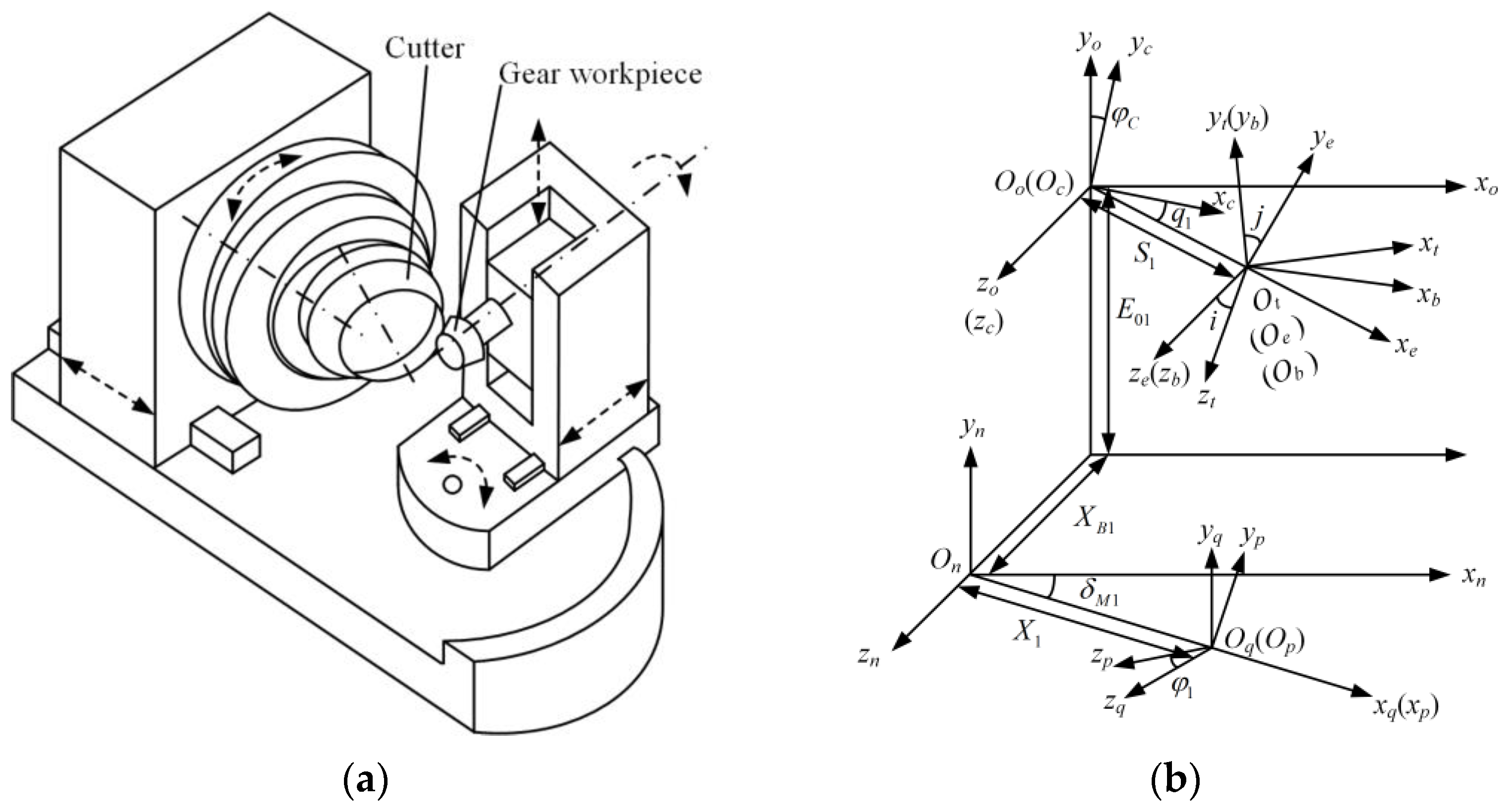
2. Establishment of Mathematical Model for Spiral Bevel Gear Tooth Surface
2.1. Establishment of Theoretical Tooth Surface Equation
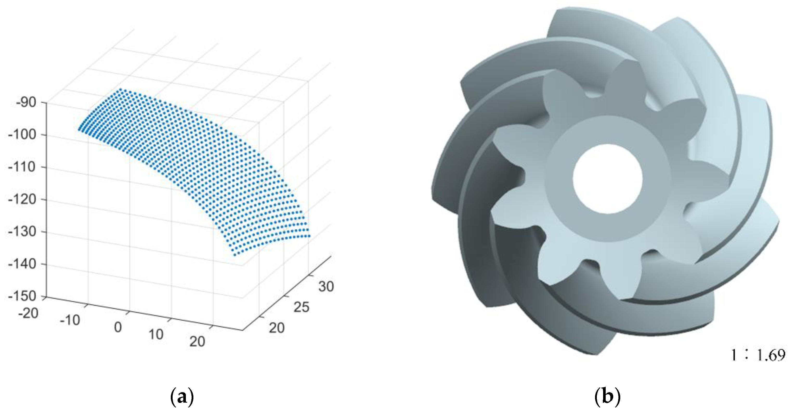
2.2. Establishment of Gear Three-Dimensional Model
3. Simulation of Spiral Bevel Gear Multi-Field Coupling Heat Treatment
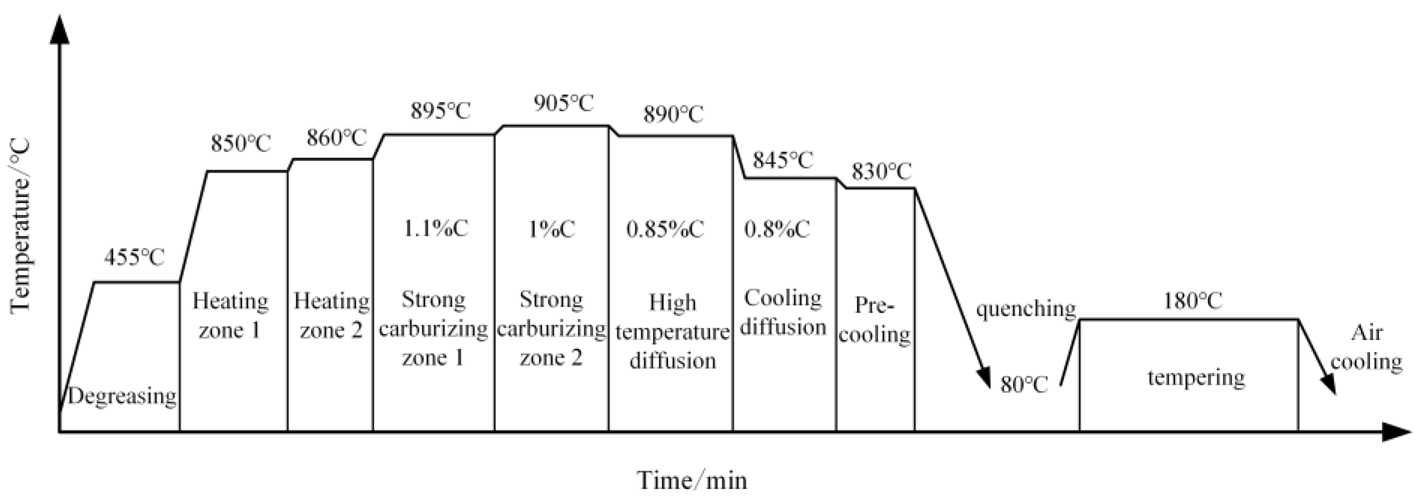
3.1. Material and Heat Treatment Process
3.2. Finite Element Mesh Generation
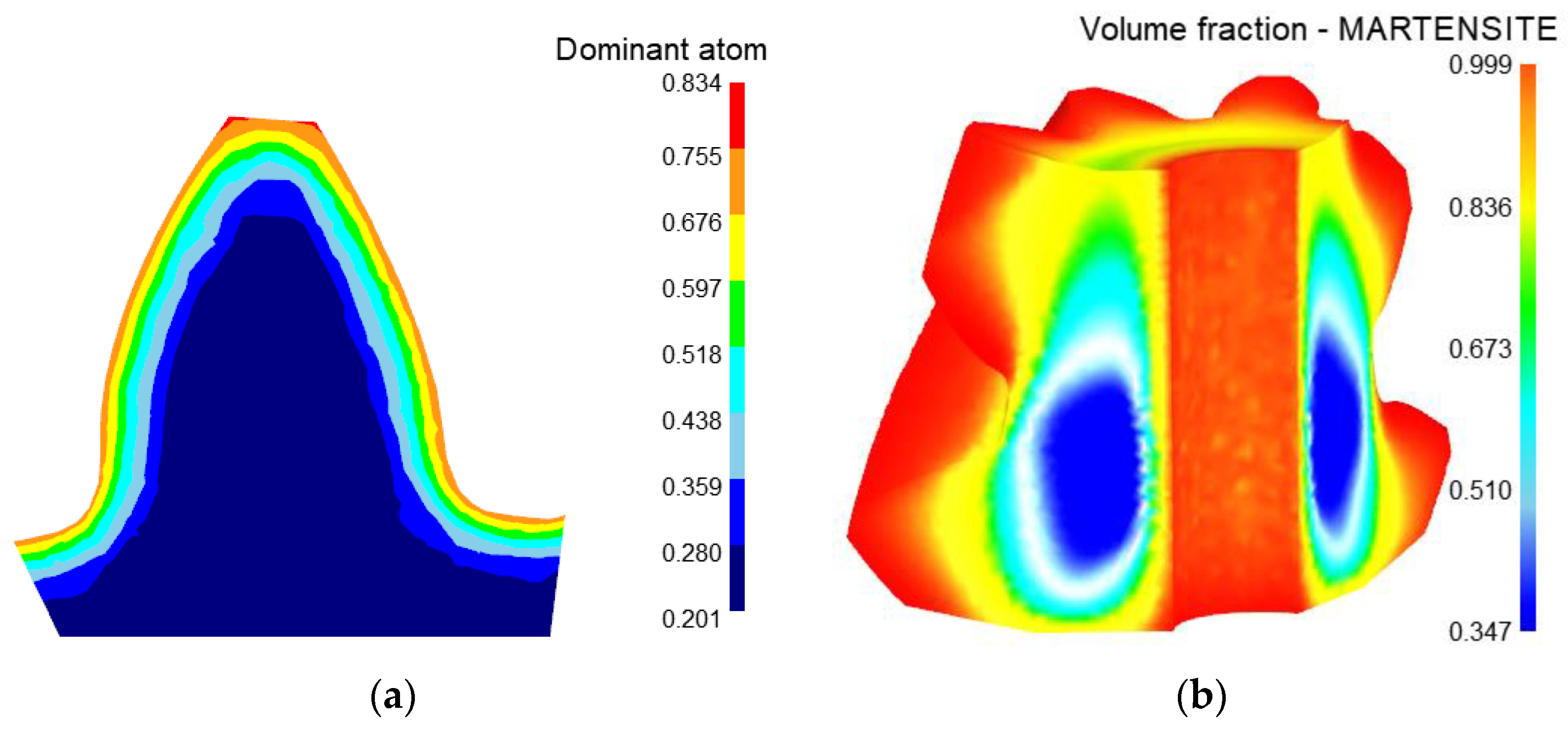
3.3. Heat Treatment Simulation Results
4. Research on the Influence of Cutting Parameters on the Tooth Form Error
4.1. Establishment of Equation for Adjusted Tooth Surface
4.2. Calculation of Tooth Form Error
4.3. The Influence of Cutting Parameters on Tooth Form Structure
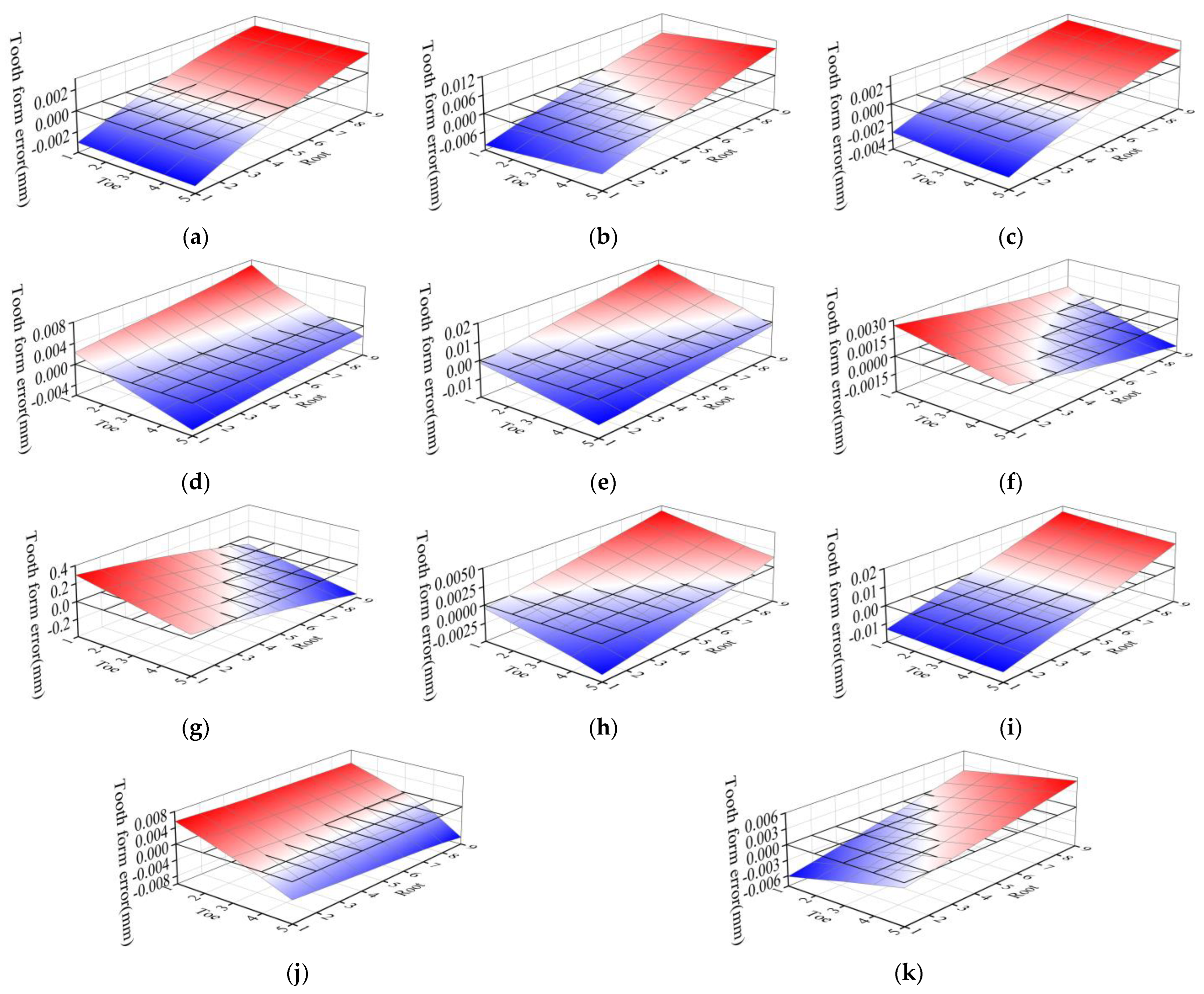
- The adjustment of tooth cutting parameters has little influence on the middle of the tooth surface, but has great influence on the heel, toe, tooth root and tooth tip of the tooth surface. The maximum value of tooth form error caused by the adjustment of cutting parameters is mainly concentrated at the opposite corner of the tooth surface and at the edge of the tooth surface.
- The influence of each cutting parameter on tooth form error is different. Among the 11 cutting parameters, the roll ratio has the greatest impact on the tooth form error, resulting in the cumulative tooth profile error of the tooth surface: 5.901 mm, followed by cutter radial setting, blade tilt angle, vertical offset, machine root angle and pressure angle of the blade, the cumulative tooth profile error was caused by 0.367 mm, 0.274 mm, 0.206 mm, 0.148 mm, 0.112 mm, respectively. Other cutting parameters have little influence on tooth form error.
- The influence of each cutting parameter on the tooth form error is different. The maximum positive value of tooth form error caused by fine adjustment of roll ratio is 0.2952 mm at the tip of the toe end, and the maximum negative value is 0.3584 mm at the root of the heel end. The roll ratio has great influence on the tooth profile and tooth direction error. The influence of vertical offset, cutter radial setting, sliding base feed setting and radius of the blade point on tooth form error mainly focuses on tooth direction, in which the vertical offset and cutter radial setting have greater effects, while the sliding base feed setting and radius of the blade point have fewer effects. The influence of machine root angle and pressure angle of the blade on tooth form error is mainly concentrated in the direction of tooth profile. The influence of blade tilt angle, blade swivel angle, basic cradle angle and increment of machine center to back on tooth form error is diagonally distributed.
4.4. Influence Weight Analysis of Cutting Parameters on Each Order Error of Tooth Form
- From the comparison of each cutting parameter, the fine adjustment amount of the roll ratio is 0.01, and the fine adjustment amount of other parameters is 0.1. Therefore, the roll ratio has the greatest impact on the errors of each order of the tooth form. From the comparison of the influence coefficients of each order, it can be seen that the adjustment of tooth cutting parameters has a greater impact on the first-order error and a smaller impact on the second-order error.
- In addition to the roll ratio, the parameters that have a great influence on the pressure angle error are, successively: cutter radial setting > blade tilt angle > increment of machine center to back > radius of the blade point > vertical offset. The parameters that have great influence on the spiral angle error are, successively: blade tilt angle > pressure angle of the blade > machine root angle > vertical offset > cutter radial setting. The parameters that have great influence on the curvature error of tooth profile are, successively: cutter radial setting > machine root angle > increment of machine center to back > radius of the blade point > Sliding base feed setting. The parameters that have great influence on the curvature error of tooth direction are, successively: cutter radial setting > vertical offset > increment of machine center to back > Machine root angle > Blade tilt angle. The parameters that have great influence on the deflection error of tooth surface are, successively: cutter radial setting > Machine root angle > Blade tilt angle > vertical offset > Pressure angle of the blade.
5. Establishment and Experimental Verification of the Reverse Adjustment Correction Model of Tooth Cutting
5.1. Establishment of the Reverse Adjustment Correction Model of Tooth Cutting
5.2. Analysis of the Results of Reverse Tooth Cutting
5.3. Experimental Verification
6. Discussion
7. Conclusions
- Based on the cutting parameters, a mathematical model of the tooth surface of spiral bevel gears was established, and the heat treatment process of the spiral bevel gear was simulated by multi-field coupling simulation. The results show that: after heat treatment, the depth of the carburized layer on the tooth surface is 1.05 mm, the carbon content on the tooth surface is 0.764 and the distribution of carbon elements is uniform. The hardness of the tooth surface is 62.8HRC, and the hardness of the gear core is 33HRC, which meets the performance requirements for heat treatment processing. The research method of using multi-field coupled simulation can reduce the cost and improve the efficiency of heat treatment research.
- The influence law of each cutting parameter on the concave tooth form error of the pinion was investigated by using the method of artificially given cutting parameters with small disturbance variables. Among each cutting parameter, the roll ratio has the greatest impact on tooth form error; The maximum tooth form error of the pinion concave surface caused by fine-tuning the roll ratio by 0.01 is −0.3584 mm, and the cumulative tooth form error is 5.901 mm. Followed by cutter radial setting, blade tilt angle, vertical offset, machine root angle and pressure angle of the blade, the above cutting parameters can be used as an important item of cutting adjustment.
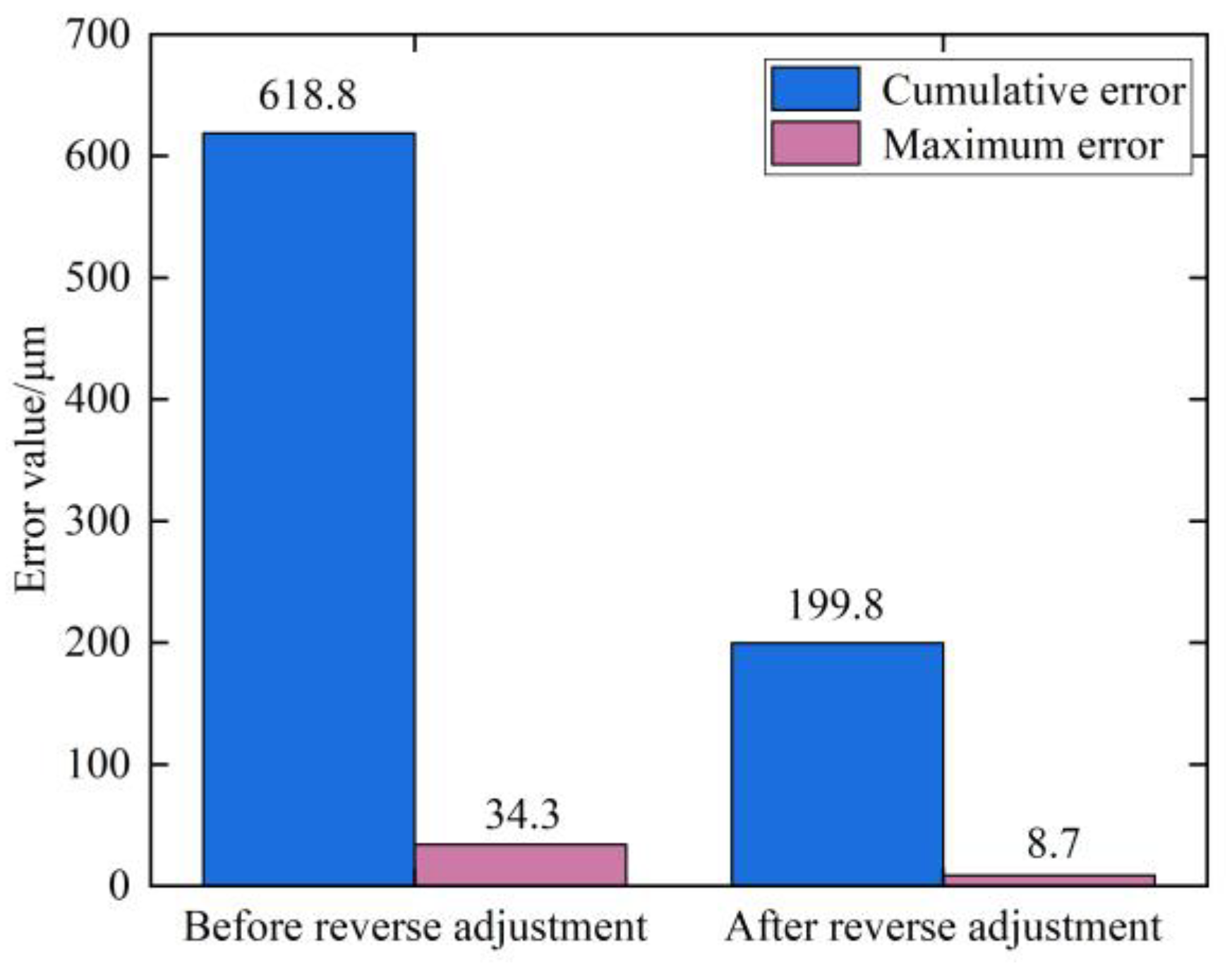
- In this paper, we propose a reverse adjustment correction model of tooth cutting for heat treatment tooth form deformation of spiral bevel gear, based on the Levenberg–Marquardat method to solve the stable and accurate numerical solution for the reverse adjustment amount of the cutting parameters. In addition, an experimental study of reverse adjustment of tooth cutting processing was carried out, and the experimental results showed that after the reverse gear cutting, the maximum tooth form error of the heat treatment deformation on the concave surface of the pinion is 8.7 μm, reduced by 74.64% compared to that before the reverse gear cutting. The cumulative tooth form error is 199.8 μm, reduced by 67.71% compared to that before the reverse gear cutting. The validity of the reverse adjustment correction model of tooth cutting was verified. The research in this paper can provide a new option for heat treatment tooth form deformation control of spiral bevel gears. The reverse adjustment correction model of tooth cutting proposed in this paper and the research on the influence of cutting parameters on tooth form can provide a technical support and theoretical reference for high-precision tooth cutting of spiral bevel gear.
Author Contributions
Funding
Institutional Review Board Statement
Informed Consent Statement
Data Availability Statement
Conflicts of Interest
References
- Shih, Y.P.; Fong, Z.H. Flank modification methodology for face-hobbing hypoid gears based on ease-off topography. J. Mech. Des. 2007, 129, 1294–1302. [Google Scholar] [CrossRef]
- Hu, Z.; Ding, H.; Peng, S.; Tang, J.; Tang, Y. A novel collaborative manufacturing model requiring both geometric and physical evaluations of spiral bevel gears by design for six sigma. Mech. Mach. Theory 2019, 133, 625–645. [Google Scholar] [CrossRef]
- Xu, H.; Zhou, Y.; He, Y.; Tang, J. An efficient approach to the five-axis flank milling of non-ferrous spiral bevel gears. Materials 2021, 14, 4848. [Google Scholar] [CrossRef] [PubMed]
- Bo, P.; González, H.; Calleja, A.; de Lacalle, L.N.L.; Bartoň, M. 5-axis double-flank CNC machining of spiral bevel gears via custom-shaped milling tools—Part I: Modeling and simulation. Precis. Eng. 2020, 62, 204–212. [Google Scholar] [CrossRef]
- Escudero, G.G.; Bo, P.; González-Barrio, H.; Calleja-Ochoa, A.; Bartoň, M.; de Lacalle, L.N.L. 5-axis double-flank CNC machining of spiral bevel gears via custom-shaped tools—Part II: Physical validations and experiments. Int. J. Adv. Manuf. Technol. 2022, 119, 1647–1658. [Google Scholar] [CrossRef]
- Ding, H.; Li, H.; Huang, R.; Tang, J. Adaptive data-driven prediction and optimization of tooth flank heat treatment deformation for aerospace spiral bevel gears by considering carburizing-meshing coupling effect. Int. J. Heat Mass Transf. 2021, 174, 121301. [Google Scholar] [CrossRef]
- Fan, Q. Computerized modeling and simulation of spiral bevel and hypoid gears manufactured by Gleason face hobbing process. J. Mech. Des. 2006, 128, 1315–1327. [Google Scholar] [CrossRef]
- Fan, Q. Kinematical simulation of face hobbing indexing and tooth surface generation of spiral bevel and hypoid gears. Gear Technol. 2006, 1, 30–38. [Google Scholar]
- Álvarez, Á.; Calleja, A.; Arizmendi, M.; González, H.; Lopez de Lacalle, L.N. Spiral bevel gears face roughness prediction produced by CNC end milling centers. Materials 2018, 11, 1301. [Google Scholar] [CrossRef]
- Khorasani, M.; Gibson, I.; Ghasemi, A.H.; Hadavi, E.; Rolfe, B. Laser subtractive and laser powder bed fusion of metals: Review of process and production features. Rapid Prototyp. J. 2023, 29, 935–958. [Google Scholar] [CrossRef]
- Dybowski, K.; Sawicki, J.; Kula, P.; Atraszkiewicz, R.; Lipa, S. The effect of the quenching method on the deformations size of gear wheels after vacuum carburizing. Arch. Metall. Mater. 2016, 61, 1057–1062. [Google Scholar] [CrossRef]
- Zhang, G.; He, X.; Zhang, Q.; Wang, W.J.; Wang, M.Q. Comparison of microstructure and heat treatment distortion of gear steels with and without Nb addition. J. Iron Steel Res. Int. 2021, 28, 488–495. [Google Scholar] [CrossRef]
- Kim, J.R.; Yoon, S.H.; Jung, Y.C.; Suh, C.H.; Kwon, T.H. A Study on the Thermal Deformation Simulation of Spur Gear According to the Heat Zones in Heat Treatment Process. J. Korean Soc. Manuf. Process Eng. 2020, 19, 60–66. [Google Scholar] [CrossRef]
- Wang, Y.Z.; Lan, Z.; Hou, L.W.; Zhao, H.P.; Zhong, Y. Heat treatment process optimization for face gears based on deformation and residual stress control. J. Chongqing Univ. 2015, 1, 9–18. [Google Scholar]
- Li, Z.; Ferguson, B.L. Gas quenching process optimization to minimize distortion of a thin-wall ring gear by simulation. HTM J. Heat Treat. Mater. 2013, 68, 35–41. [Google Scholar] [CrossRef]
- Sun, P.; Pang, D.; Qi, X.; Luo, N. The Heat Treatment Deformation Law and the Improvement of Accuracy of the Transmission Gear. In Proceedings of the China SAE Congress 2018: Selected Papers; Springer: Singapore, 2020; pp. 647–661. [Google Scholar]
- Artoni, A.; Gabiccini, M.; Kolivand, M. Ease-off based compensation of tooth surface deviations for spiral bevel and hypoid gears: Only the pinion needs corrections. Mech. Mach. Theory 2013, 61, 84–101. [Google Scholar] [CrossRef]
- Mu, Y.; He, X. Design and dynamic performance analysis of high-contact-ratio spiral bevel gear based on the higher-order tooth surface modification. Mech. Mach. Theory 2021, 161, 104312. [Google Scholar] [CrossRef]
- Xiang, S.; Li, H.; Deng, M.; Yang, J. Geometric error analysis and compensation for multi-axis spiral bevel gears milling machine. Mech. Mach. Theory 2018, 121, 59–74. [Google Scholar] [CrossRef]
- Peng, S.; Ding, H.; Tang, J.; Zhou, Y. Collaborative machine tool settings compensation considering both tooth flank geometrical and physical performances for spiral bevel and hypoid gears. J. Manuf. Process. 2020, 54, 169–179. [Google Scholar] [CrossRef]
- Lei, D.; Rong, K.; Song, B.; Ding, H.; Tang, J. Digital twin modeling for tooth surface grinding considering low-risk transmission performance of non-orthogonal aviation spiral bevel gears. ISA Trans. 2022, 128, 646–663. [Google Scholar] [CrossRef]
- Ding, H.; Tang, J.; Zhong, J. Accurate nonlinear modeling and computing of grinding machine settings modification considering spatial geometric errors for hypoid gears. Mech. Mach. Theory 2016, 99, 155–175. [Google Scholar] [CrossRef]
- Ding, H.; Wan, Z.; Zhou, Y.; Tang, J. A data-driven programming of the human-computer interactions for modeling a collaborative manufacturing system of hypoid gears by considering both geometric and physical performances. Robot. Comput. -Integr. Manuf. 2018, 51, 121–138. [Google Scholar] [CrossRef]
- Kim, D.W.; Cho, H.H.; Lee, W.B.; Cho, K.T.; Cho, Y.G.; Kim, S.J.; Han, H.N. A finite element simulation for carburizing heat treatment of automotive gear ring incorporating transformation plasticity. Mater. Des. 2016, 99, 243–253. [Google Scholar] [CrossRef]
- Bouissa, Y.; Bohlooli, N.; Shahriari, D.; Champliaud, H.; Morin, J.B.; Jahazi, M. FEM modeling and experimental validation of quench-induced distortions of large size steel forgings. J. Manuf. Process. 2020, 58, 592–605. [Google Scholar] [CrossRef]
- Esfahani, A.K.; Babaei, M.; Sarrami-Foroushani, S. A numerical model coupling phase transformation to predict microstructure evolution and residual stress during quenching of 1045 steel. Math. Comput. Simul. 2021, 179, 1–22. [Google Scholar] [CrossRef]
- Litvin, F.L.; Fuentes, A.; Hayasaka, K. Design, manufacture, stress analysis, and experimental tests of low-noise high endurance spiral bevel gears. Mech. Mach. Theory 2006, 41, 83–118. [Google Scholar] [CrossRef]
- Wang, J.; Kong, L.; Liu, B.; Hu, X.; Yu, X.; Kong, W. The mathematical model of spiral bevel gears-A review. Stroj. Vestn.-J. Mech. Eng. 2014, 60, 93–105. [Google Scholar] [CrossRef]
- Shih, Y.P. A novel ease-off flank modification methodology for spiral bevel and hypoid gears. Mech. Mach. Theory 2010, 45, 1108–1124. [Google Scholar] [CrossRef]
- Shih, Y.P.; Fong, Z.H.; Lin, G.C.Y. Mathematical model for a universal face hobbing hypoid gear generator. J. Mech. Des. 2007, 129, 38–47. [Google Scholar] [CrossRef]
- Litvin, F.L.; Fuentes, A. Gear Geometry and Applied Theory; Cambridge University Press: Cambridge, UK, 2004. [Google Scholar]
- Fuentes-Aznar, A.; Ruiz-Orzaez, R.; Gonzalez-Perez, I. Numerical approach for determination of rough-cutting machine-tool settings for fixed-setting face-milled spiral bevel gears. Mech. Mach. Theory 2017, 112, 22–42. [Google Scholar] [CrossRef]
- Zhou, Z.; Tang, J.; Ding, H. Accurate modification methodology of universal machine tool settings for spiral bevel and hypoid gears. Proc. Inst. Mech. Eng. Part B J. Eng. Manuf. 2018, 232, 339–349. [Google Scholar] [CrossRef]
- Ding, H.; Tang, J.; Zhou, Y.; Zhong, J.; Wan, G. A multi-objective correction of machine settings considering loaded tooth contact performance in spiral bevel gears by nonlinear interval number optimization. Mech. Mach. Theory 2017, 113, 85–108. [Google Scholar] [CrossRef]
- Ding, H.; Wan, G.; Zhou, Y.; Tang, J.; Zhou, Z. Nonlinearity analysis based algorithm for indentifying machine settings in the tooth flank topography correction for hypoid gears. Mech. Mach. Theory 2017, 113, 1–21. [Google Scholar] [CrossRef]
- Ding, H.; Tang, J.; Zhong, J.; Zhou, Z. A hybrid modification approach of machine-tool setting considering high tooth contact performance in spiral bevel and hypoid gears. J. Manuf. Syst. 2016, 41, 228–238. [Google Scholar] [CrossRef]
- Pires, R.; Mili, L.; Chagas, G. Robust complex-valued Levenberg-Marquardt algorithm as applied to power flow analysis. Int. J. Electr. Power Energy Syst. 2019, 113, 383–392. [Google Scholar] [CrossRef]
- Álvarez, Á.; Calleja, A.; Ortega, N.; De Lacalle, L.N.L. Five-axis milling of large spiral bevel gears: Toolpath definition, finishing, and shape errors. Metals 2018, 8, 353. [Google Scholar] [CrossRef]





| Gear Parameters | Pinion |
|---|---|
| Rotation | left |
| Number of tooth Z | 9 |
| 45 | |
| 7.1795 | |
| 20 | |
| 35 | |
| 136.412 | |
| 13 | |
| 11.67 | |
| 16.94 |
| The Parameters of Cutting | Concave | Convex |
|---|---|---|
| 14 | 31 | |
| 113.3 | 115.3 | |
| 13.367 | 13.5 | |
| −4.75 | 5.1 | |
| 0 | 0 | |
| 7.99 | 15.37 | |
| 106.709 | 92.126 | |
| 133.348 | 142.856 | |
| 24.083 | 26.35 | |
| 44.75 | 33.667 | |
| 4.27972 | 4.63017 |
| Composition | C | Si | Mn | Cr | Ti | S | P | Fe |
|---|---|---|---|---|---|---|---|---|
| Mass fraction (%) | 0.2 | 0.21 | 1.02 | 1.23 | 0.04 | 0.014 | 0.023 | 97.263 |
| The Parameters of Tooth Cutting | |||||
|---|---|---|---|---|---|
| Pressure angle of the blade | −0.0008019 | 0.0013203 | −0.0000559 | −0.0000435 | −0.0001384 |
| Radius of the blade point | −0.0019004 | 0.0004029 | 0.0002002 | −0.0000031 | 0.0000910 |
| Machine root angle | 0.0017280 | 0.0010451 | −0.0005273 | −0.0000541 | −0.0002137 |
| Increment of machine center to back | −0.0020634 | −0.0005740 | 0.0003825 | 0.0000951 | 0.0001293 |
| Vertical offset | −0.0018171 | −0.0007051 | 0.0001124 | 0.0001276 | 0.0001482 |
| Sliding base feed setting | −0.0017299 | 0.0003203 | 0.0001863 | 0.0000006 | 0.0000908 |
| Basic cradle angle | −0.0008762 | 0.0004222 | −0.0000078 | 0.0000148 | 0.0000185 |
| Cutter radial setting | −0.0072466 | 0.0006348 | 0.0007961 | 0.0001883 | 0.0002969 |
| Blade tilt angle | −0.0025545 | 0.0020072 | −0.0000667 | 0.0000463 | −0.0001970 |
| Blade swivel angle | 0.0008358 | 0.0002963 | −0.0001347 | −0.0000281 | −0.0001039 |
| Roll ratio | 0.1006654 | 0.0385447 | −0.0185606 | −0.0056669 | −0.0087164 |
| The Parameters of Cutting | Value before Reverse | Amount of Reverse Adjustment | Value after Reverse |
|---|---|---|---|
| 14 | −0.21499 | 13.78501 | |
| 13.367 | −0.16114 | 13.20586 | |
| 0 | −0.37099 | −0.37099 | |
| 133.348 | 0.18277 | 133.53077 | |
| 24.083 | 0.14494 | 24.22794 | |
| 4.27972 | −0.00021 | 4.27951 |
Disclaimer/Publisher’s Note: The statements, opinions and data contained in all publications are solely those of the individual author(s) and contributor(s) and not of MDPI and/or the editor(s). MDPI and/or the editor(s) disclaim responsibility for any injury to people or property resulting from any ideas, methods, instructions or products referred to in the content. |
© 2023 by the authors. Licensee MDPI, Basel, Switzerland. This article is an open access article distributed under the terms and conditions of the Creative Commons Attribution (CC BY) license (https://creativecommons.org/licenses/by/4.0/).
Share and Cite
Liu, G.; Huo, X.; Deng, S. Control of Tooth Form Deformation in Heat Treatment of Spiral Bevel Gears Based on Reverse Adjustment of Cutting Parameters. Materials 2023, 16, 4183. https://doi.org/10.3390/ma16114183
Liu G, Huo X, Deng S. Control of Tooth Form Deformation in Heat Treatment of Spiral Bevel Gears Based on Reverse Adjustment of Cutting Parameters. Materials. 2023; 16(11):4183. https://doi.org/10.3390/ma16114183
Chicago/Turabian StyleLiu, Ganhua, Xiaodong Huo, and Shiyi Deng. 2023. "Control of Tooth Form Deformation in Heat Treatment of Spiral Bevel Gears Based on Reverse Adjustment of Cutting Parameters" Materials 16, no. 11: 4183. https://doi.org/10.3390/ma16114183
APA StyleLiu, G., Huo, X., & Deng, S. (2023). Control of Tooth Form Deformation in Heat Treatment of Spiral Bevel Gears Based on Reverse Adjustment of Cutting Parameters. Materials, 16(11), 4183. https://doi.org/10.3390/ma16114183


