
Porous Material (Titanium Gas Diffusion Layer) in Proton Exchange Membrane Fuel Cell/Electrolyzer: Fabrication Methods & GeoDict: A Critical Review
 and
and
Abstract
:1. Introduction
Cathode: O2 + 4H+ + 4e− → 2H2O
2. Types of Fuel Cells Based on Electrolyte
Proton Exchange Membrane Fuel Cell
3. Gas Diffusion Layer
3.1. GDL Material
3.1.1. Carbon GDL
3.1.2. Titanium GDL
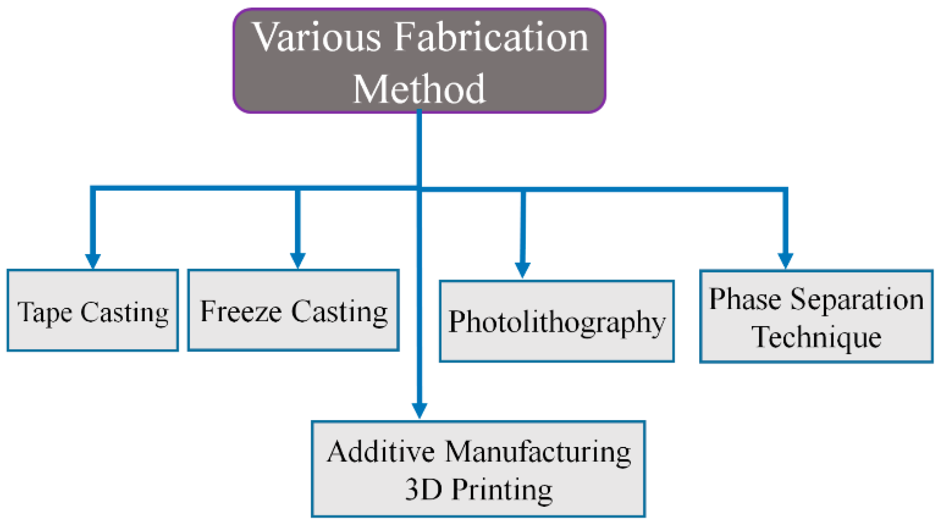
4. Fabrication Technologies
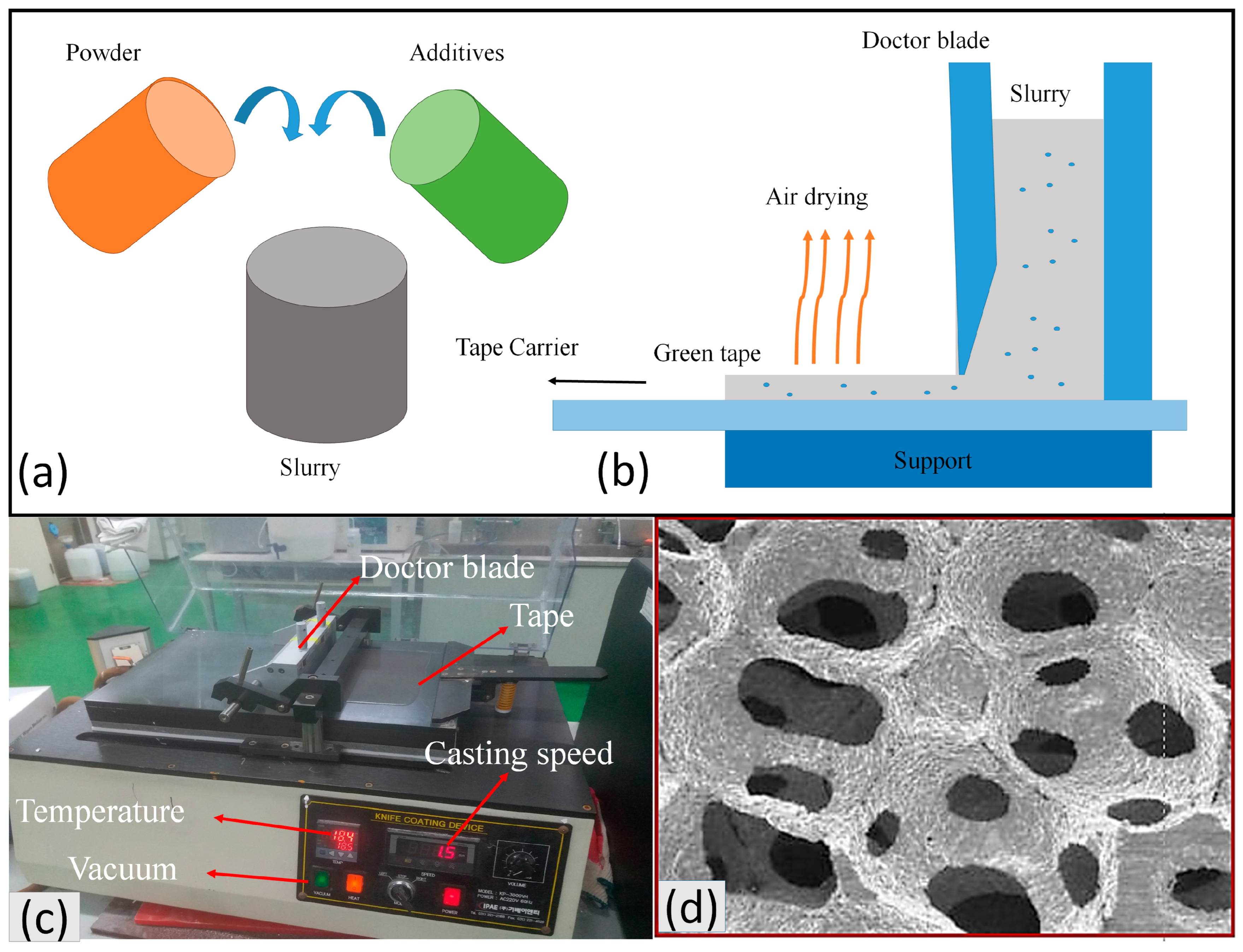
4.1. Tape Casting
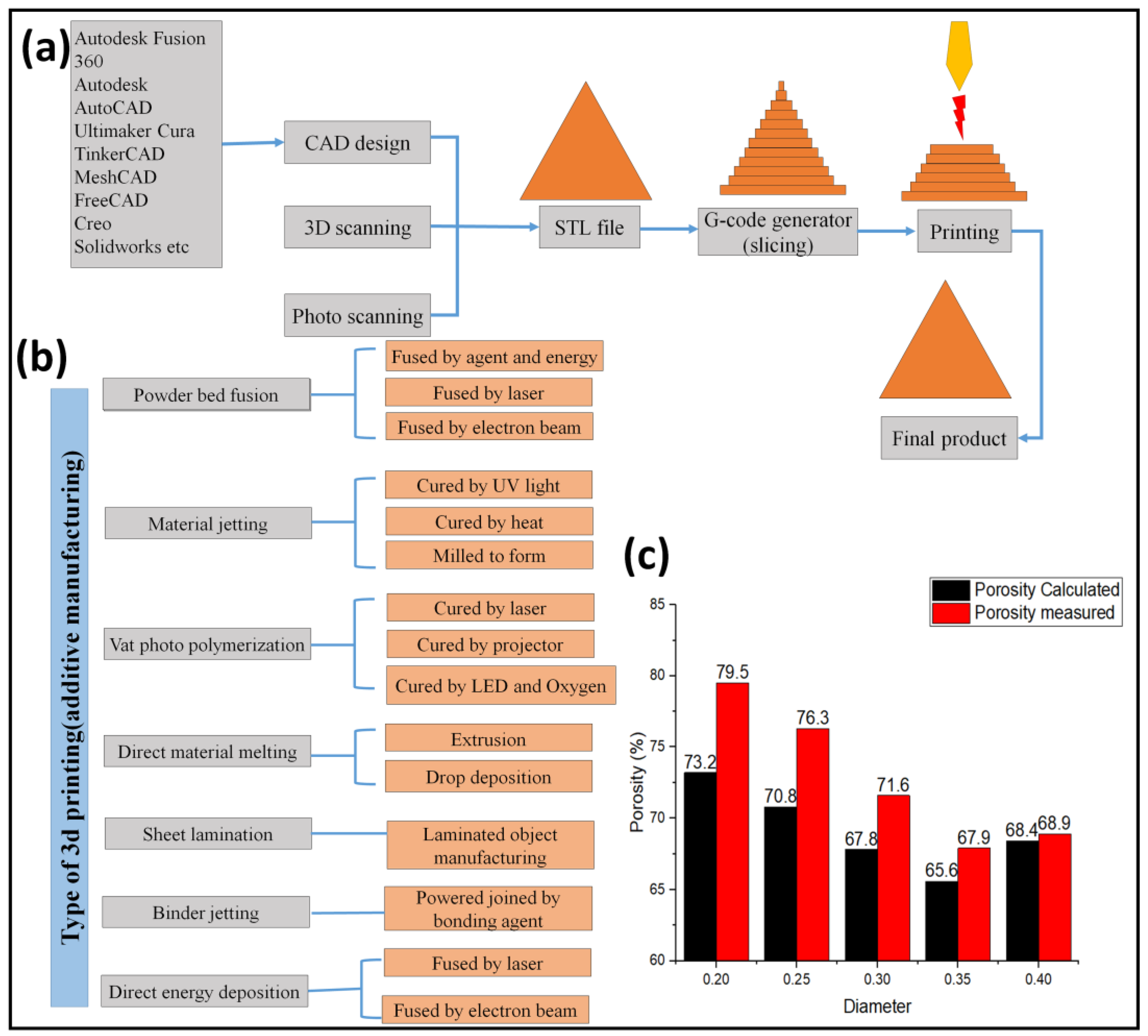
4.2. Additive Manufacturing (3D Printing)
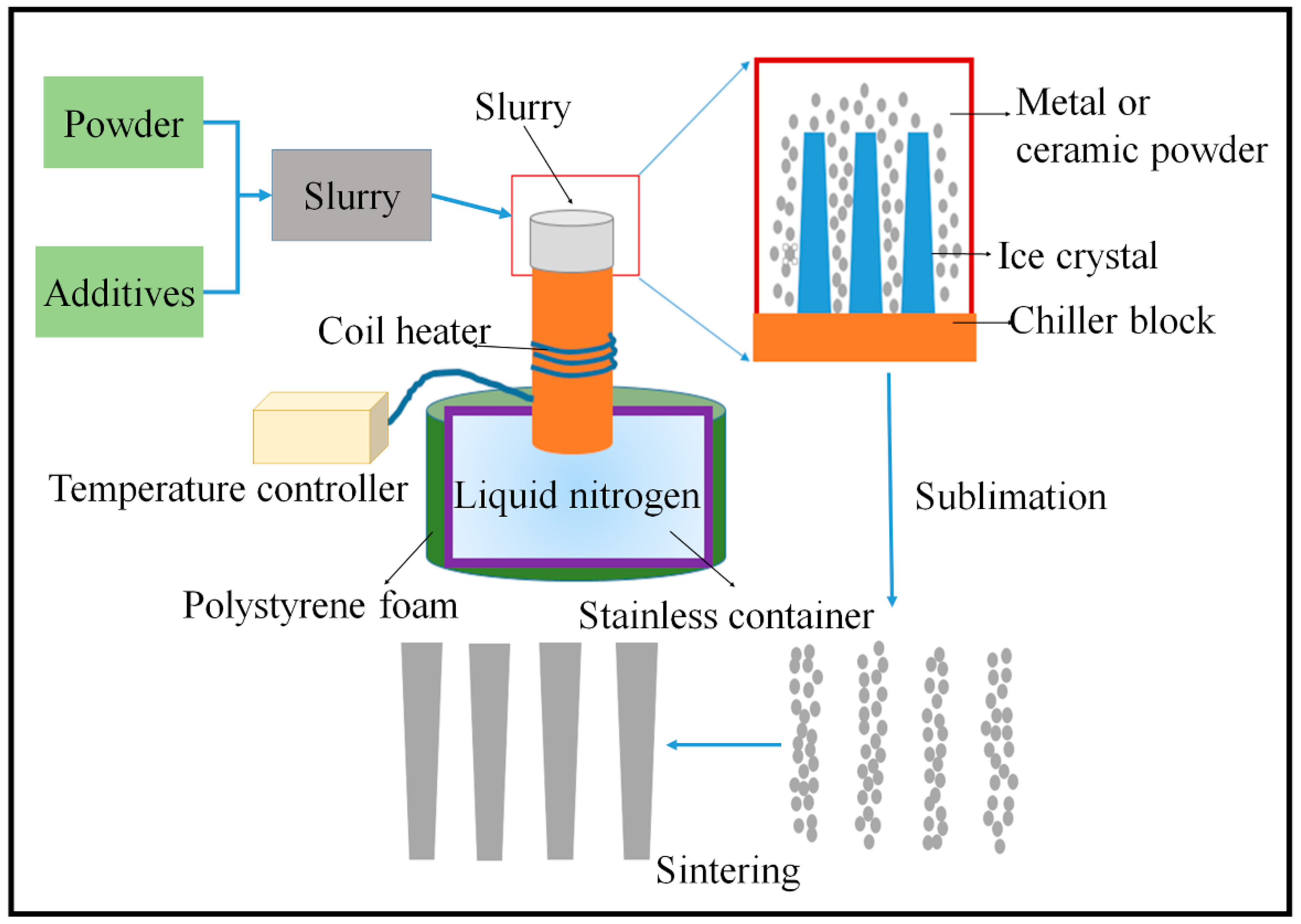
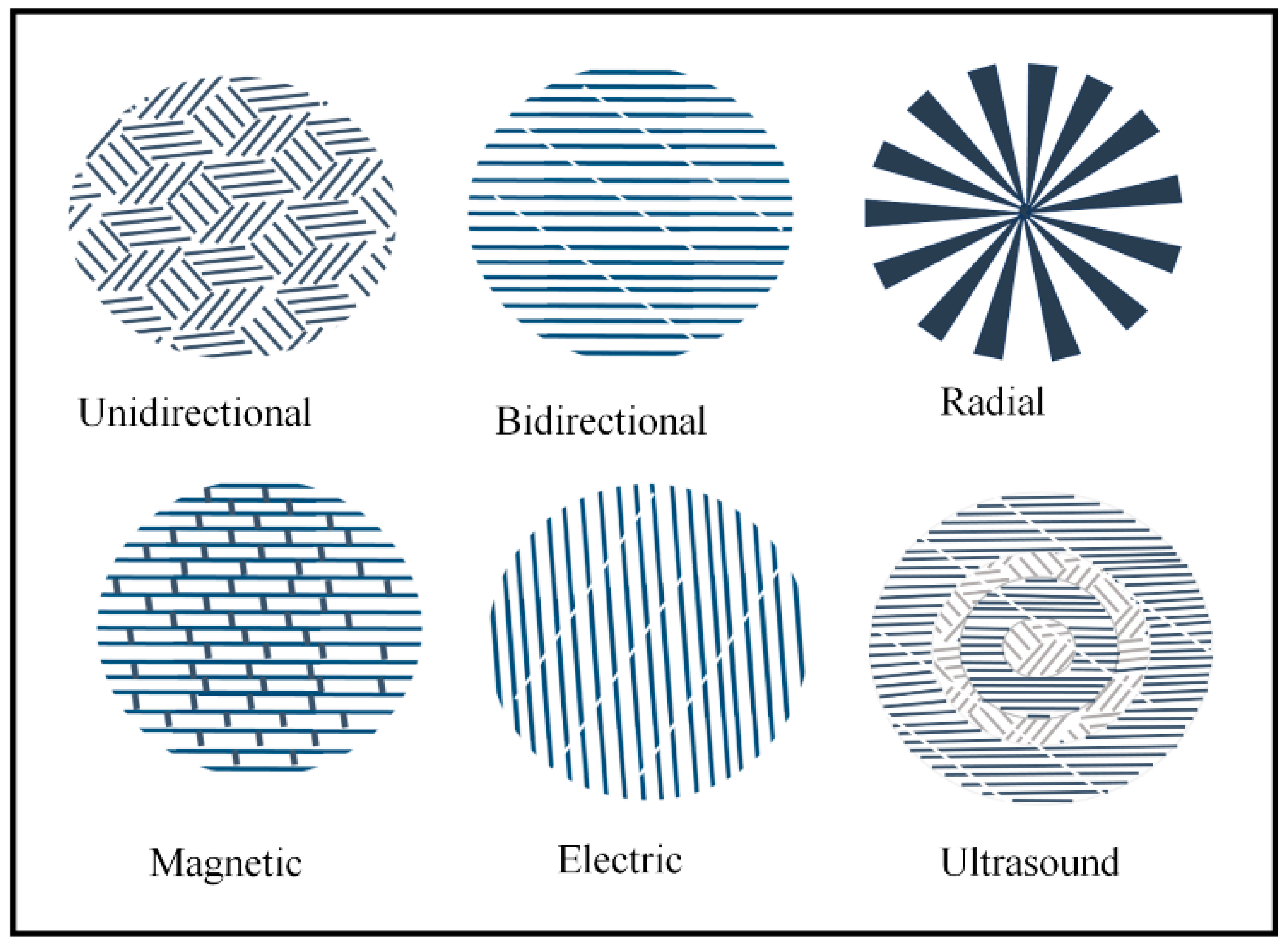
4.3. Freeze Casting
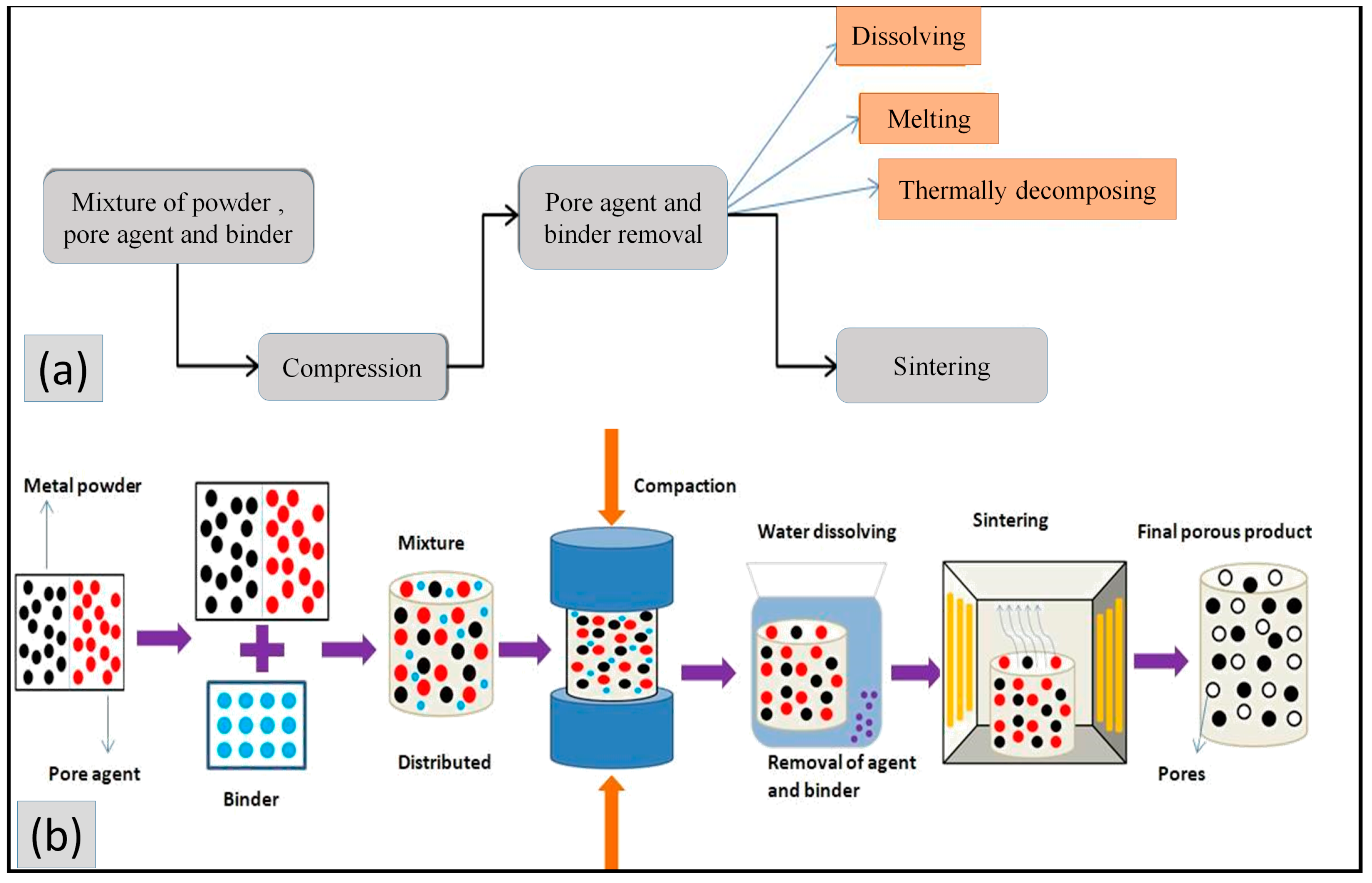
4.4. Phase Separation Technique (PST)
4.4.1. Sintering Dissolution Process
4.4.2. Thermally Stimulated Decomposition
4.4.3. Thermally Melted Elimination Technique
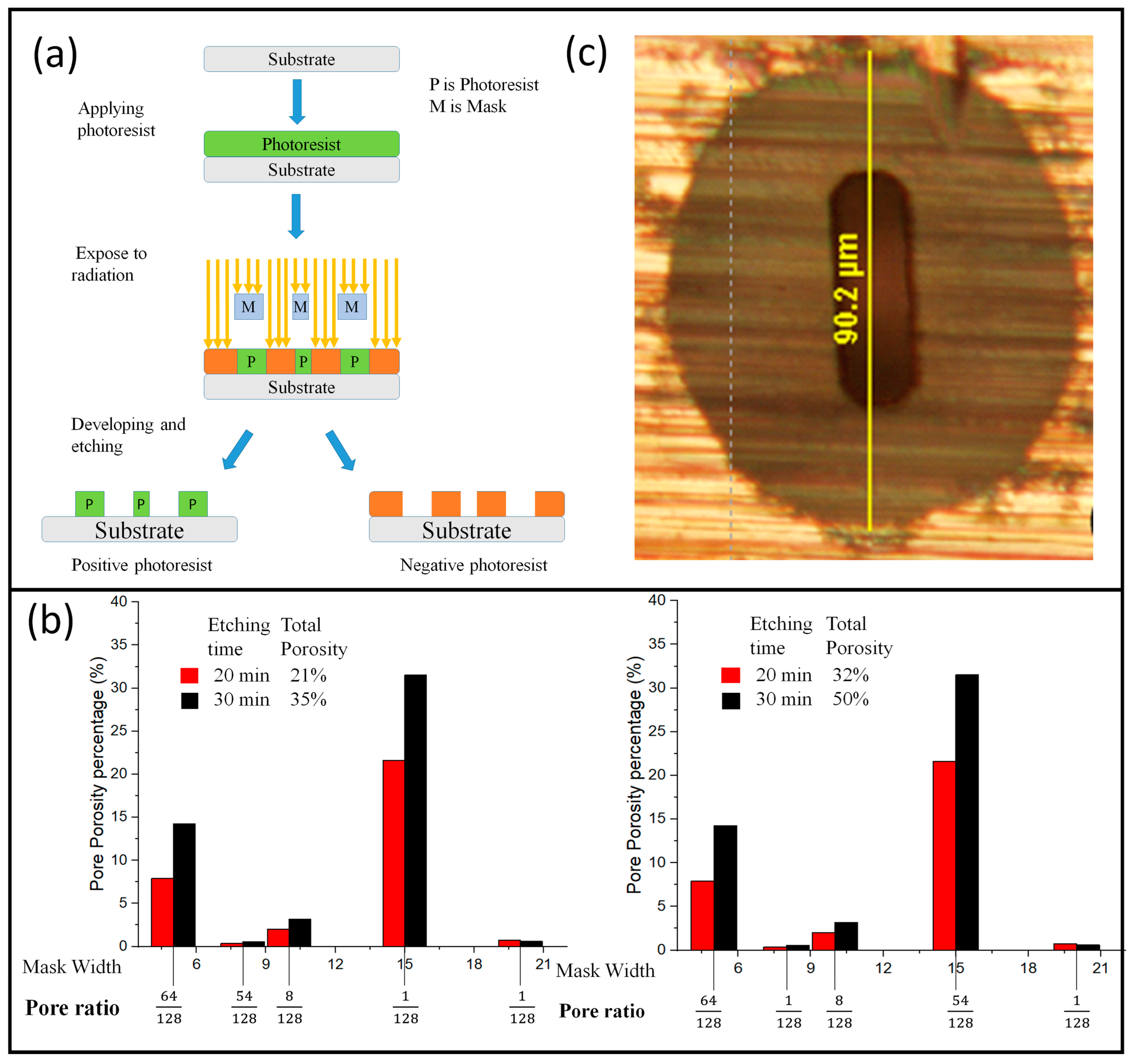
4.5. Lithography
- Electron beam lithography
- Ion beam lithography
- Photolithography
- X-ray lithography
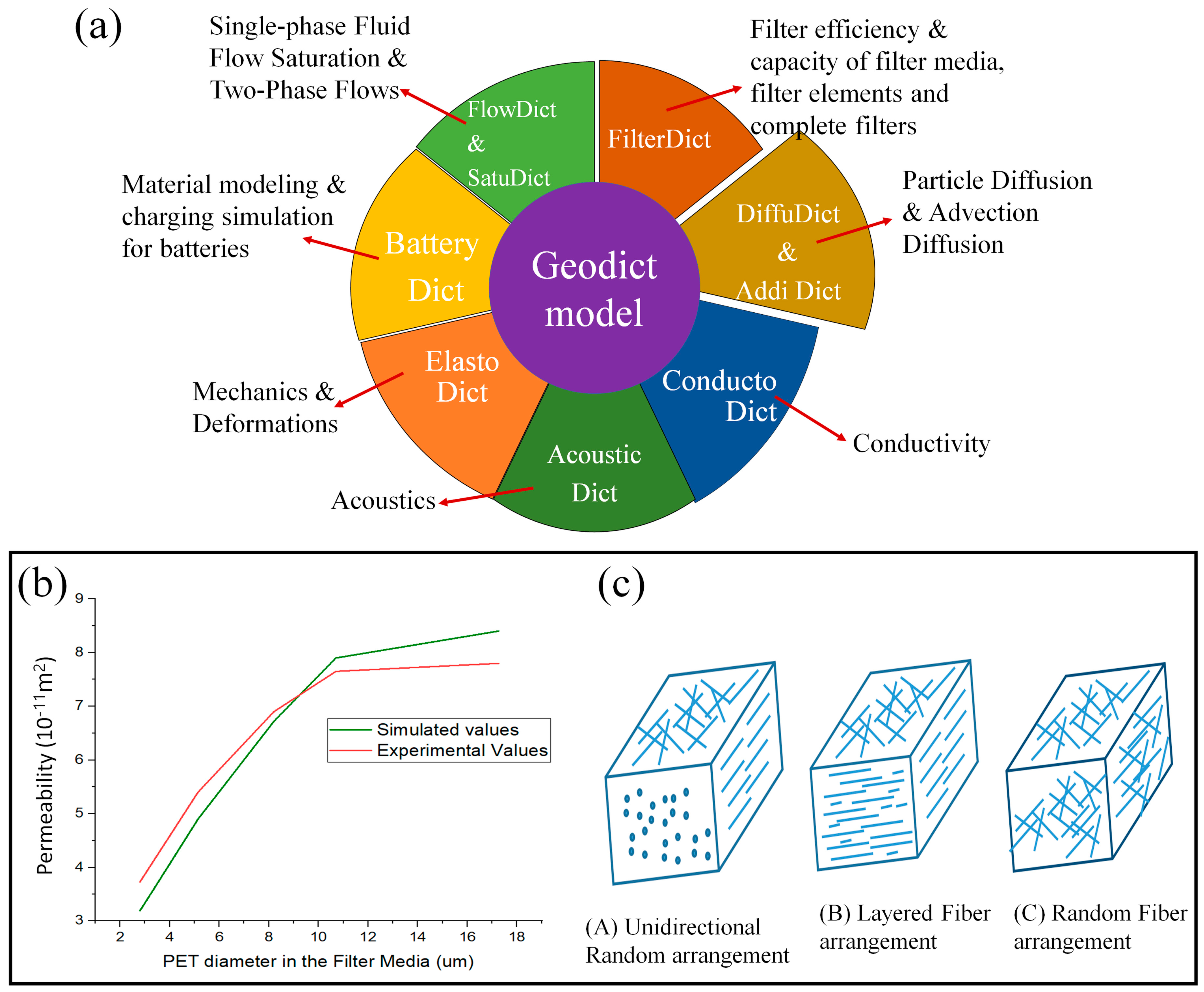
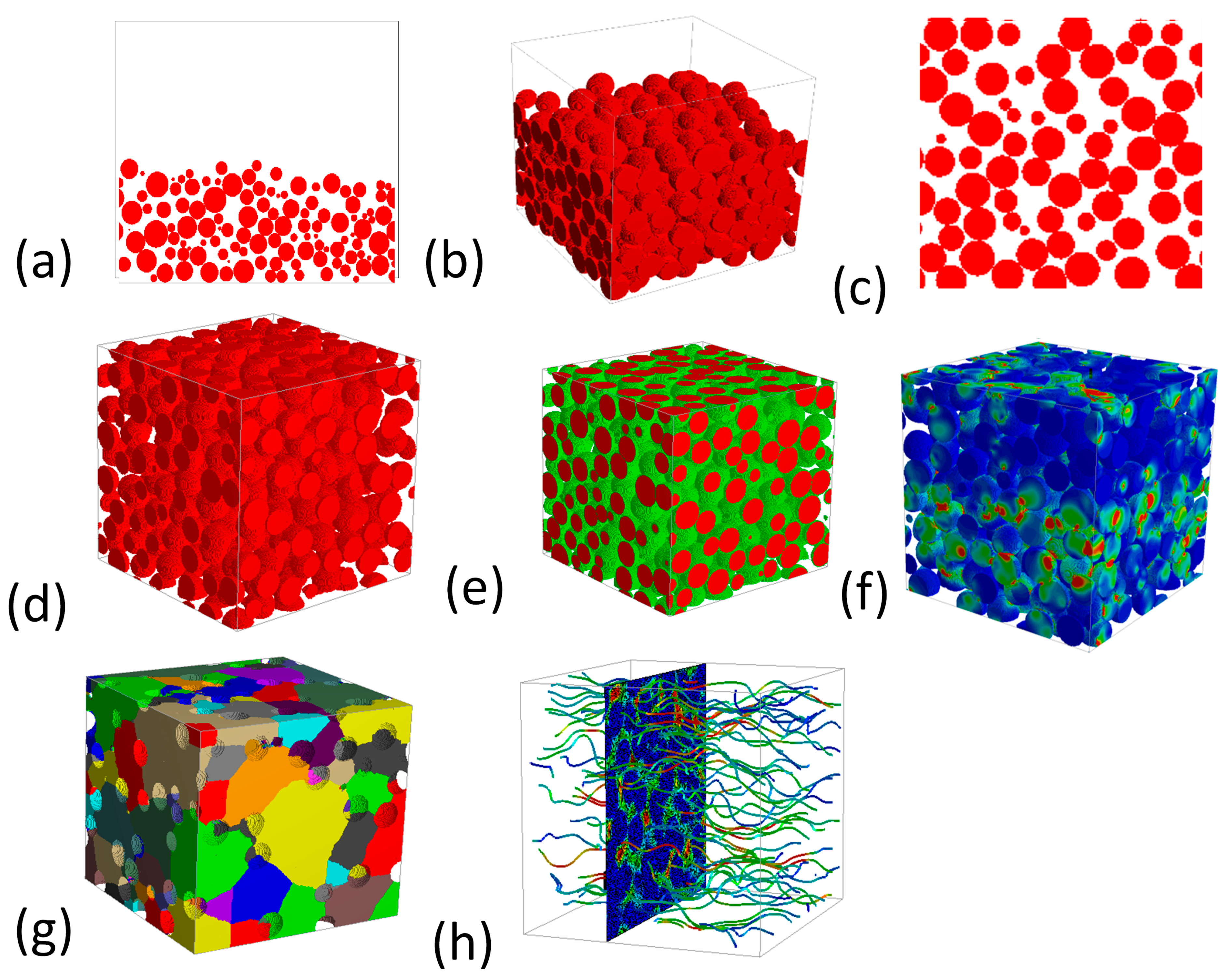
5. GeoDict

| Filter Section | Upscaled for the Whole Filter | Experiment | Simulation Time | |
|---|---|---|---|---|
| GeoDict efficiency | 2.6% | 96.96% | 96.5 | 12.88 weeks |
| StarCCM+ efficiency | 2.8% | 97.6% | 96.5 | 10 min |
6. Conclusions and Recommendations
Funding
Institutional Review Board Statement
Informed Consent Statement
Data Availability Statement
Conflicts of Interest
Abbreviations
| PEMFC | Proton exchange membrane fuel cell |
| GDL | Gas diffusion layer |
| 2D | Two dimensional |
| 3D | Three dimensional |
| PAFC | Phosphoric acid fuel cell |
| AFC | Alkaline fuel cell |
| MCFC | Molten carbonate fuel cell |
| SOFC | Solid oxide fuel cell |
| PEM | Proton exchange membrane |
| CL | Catalyst layer |
| MEA | Membrane electrode assembly |
| PVA | Polyvinyl alcohol |
| PST | Phase separation technique |
| CAD | Computer-aided design |
References
- Lee, H.; Choi, C.-W.; Kang, K.-W.; Jin, J.-W. A Study on the Evaluation of Effective Properties of Randomly Distributed Gas Diffusion Layer (GDL) Tissues with Different Compression Ratios. Appl. Sci. 2020, 10, 7407. [Google Scholar] [CrossRef]
- Zhang, F.-Y.; Advani, S.G.; Prasad, A.K. Performance of a metallic gas diffusion layer for PEM fuel cells. J. Power Sources 2008, 176, 293–298. [Google Scholar] [CrossRef]
- Marshall, A. Electrocatalysts for the Oxygen Evolution Electrode in Water Electrolysers Using Proton Exchange Membranes: Synthesis and Characterisation. Ph.D. Thesis, Fakultet for Naturvitenskap og Teknologi, Trondheim, Norway, 2005. [Google Scholar]
- Wang, Y.; Chen, K.S.; Mishler, J.; Cho, S.C.; Adroher, X.C. A review of polymer electrolyte membrane fuel cells: Technology, applications, and needs on fundamental research. Appl. Energy 2011, 88, 981–1007. [Google Scholar] [CrossRef] [Green Version]
- Xie, Z.K.; Yamada, Y.; Banno, T. Fabrication of Micro Porous Aluminum by Powder Sintering. Mater. Sci. Forum 2007, 539-543, 2778–2781. [Google Scholar] [CrossRef]
- Vaghari, H.; Jafarizadeh-Malmiri, H.; Berenjian, A.; Anarjan, N. Recent advances in application of chitosan in fuel cells. Sustain. Chem. Process. 2013, 1, 16. [Google Scholar] [CrossRef] [Green Version]
- Borgardt, E.; Panchenko, O.; Hackemüller, F.J.; Giffin, J.; Bram, M.; Müller, M.; Lehnert, W.; Stolten, D. Mechanical characterization and durability of sintered porous transport layers for polymer electrolyte membrane electrolysis. J. Power Sources 2018, 374, 84–91. [Google Scholar] [CrossRef]
- Reddy, B.M.; Samuel, P. Technology advancements and trends in development of proton exchange membrane fuel cell hybrid electric vehicles in India: A review. J. Green Eng. 2017, 7, 361–384. [Google Scholar] [CrossRef] [Green Version]
- Peighambardoust, S.; Rowshanzamir, S.; Amjadi, M. Review of the proton exchange membranes for fuel cell applications. Int. J. Hydrogen Energy 2010, 35, 9349–9384. [Google Scholar] [CrossRef]
- Hernandez-Aldave, S.; Andreoli, E. Fundamentals of Gas Diffusion Electrodes and Electrolysers for Carbon Dioxide Utilisation: Challenges and Opportunities. Catalysts 2020, 10, 713. [Google Scholar] [CrossRef]
- Park, S.; Lee, J.-W.; Popov, B.N. A review of gas diffusion layer in PEM fuel cells: Materials and designs. Int. J. Hydrogen Energy 2012, 37, 5850–5865. [Google Scholar] [CrossRef]
- Omrani, R.; Shabani, B. Gas diffusion layer modifications and treatments for improving the performance of proton exchange membrane fuel cells and electrolysers: A review. Int. J. Hydrogen Energy 2017, 42, 28515–28536. [Google Scholar] [CrossRef]
- Mo, J.; Steen, S.M.; Retterer, S.; Cullen, D.A.; Terekhov, A.; Zhang, F.-Y. Mask-Patterned Wet Etching of Thin Titanium Liquid/Gas Diffusion Layers for a PEMEC. ECS Trans. 2015, 66, 3–10. [Google Scholar] [CrossRef]
- Li, J.P.; Li, S.H.; de Groot, K.; Layrolle, P. Preparation and Characterization of Porous Titanium. Key Eng. Mater. 2001, 218-220, 51–54. [Google Scholar] [CrossRef]
- Emsley, J. Nature’s Building Blocks: An AZ Guide to the Elements; Oxford University Press: Oxford, UK, 2011. [Google Scholar]
- Staff, A.I. ASM Handbook: Properties and Selection: Nonferrous Alloys and Special-Purpose Materials; ASM International: Materials Park, OH, USA, 1991; Volume 2. [Google Scholar]
- Periodic Table Element Comparison: Compare Elements-Titanium vs Carbon. SCHOOLMYKIDS. Available online: https://www.schoolmykids.com/learn/periodic-table/compare-titanium-carbon (accessed on 15 February 2023).
- Aşık, E.E.; Bor, Ş. Fatigue behavior of Ti–6Al–4V foams processed by magnesium space holder technique. Mater. Sci. Eng. A 2015, 621, 157–165. [Google Scholar] [CrossRef]
- Steen, S.M.; Mo, J.; Kang, Z.; Yang, G.; Zhang, F.-Y. Investigation of titanium liquid/gas diffusion layers in proton exchange membrane electrolyzer cells. Int. J. Green Energy 2017, 14, 162–170. [Google Scholar] [CrossRef]
- Zhou, W.; Tang, Y.; Song, R.; Jiang, L.; Hui, K. Characterization of electrical conductivity of porous metal fiber sintered sheet using four-point probe method. Mater. Des. 2012, 37, 161–165. [Google Scholar] [CrossRef]
- Cuevas, F.G.; Montes, J.M.; Cintas, J.; Urban, P. Electrical conductivity and porosity relationship in metal foams. J. Porous Mater. 2009, 16, 675–681. [Google Scholar] [CrossRef]
- Jin, M.; Chen, C.; Lu, T. The mechanical behavior of porous metal fiber sintered sheets. J. Mech. Phys. Solids 2013, 61, 161–174. [Google Scholar] [CrossRef]
- Zhou, W.; Tang, Y.; Liu, B.; Song, R.; Jiang, L.; Hui, K.; Yao, H. Compressive properties of porous metal fiber sintered sheet produced by solid-state sintering process. Mater. Des. 2012, 35, 414–418. [Google Scholar] [CrossRef]
- Karpenko-Jereb, L.; Sternig, C.; Fink, C.; Hacker, V.; Theiler, A.; Tatschl, R. Theoretical study of the influence of material parameters on the performance of a polymer electrolyte fuel cell. J. Power Sources 2015, 297, 329–343. [Google Scholar] [CrossRef]
- Hossain, M.S.; Shabani, B. Metal foams application to enhance cooling of open cathode polymer electrolyte membrane fuel cells. J. Power Sources 2015, 295, 275–291. [Google Scholar] [CrossRef]
- Omrani, R. Review of gas diffusion layer for proton exchange membrane-based technologies with a focus on unitised regen-erative fuel cells. Int. J. Hydrogen Energy 2019, 44, 3834–3860. [Google Scholar] [CrossRef]
- Lin, H.H.; Cheng, C.H.; Soong, C.Y.; Chen, F.; Yan, W.M. Optimization of key parameters in the proton exchange membrane fuel cell. J. Power Sources 2006, 162, 246–254. [Google Scholar] [CrossRef]
- Alhazmi, N.; Ingham, D.B.; Ismail, M.S.; Hughes, K.J.; Ma, L.; Pourkashanian, M. Effect of the anisotropic thermal conductivity of GDL on the performance of PEM fuel cells. Int. J. Hydrogen Energy 2013, 38, 603–611. [Google Scholar] [CrossRef]
- Chan, C.; Zamel, N.; Li, X.; Shen, J. Experimental measurement of effective diffusion coefficient of gas diffusion layer/microporous layer in PEM fuel cells. Electrochim. Acta 2012, 65, 13–21. [Google Scholar] [CrossRef] [Green Version]
- Hwang, C.M.; Ishida, M.; Ito, H.; Maeda, T.; Nakano, A.; Hasegawa, Y.; Yokoi, N.; Kato, A.; Yoshida, T. Influence of properties of gas diffusion layers on the performance of polymer electrolyte-based unitized reversible fuel cells. Int. J. Hydrogen Energy 2011, 36, 1740–1753. [Google Scholar] [CrossRef] [Green Version]
- Zhao, B.; Gain, A.K.; Ding, W.; Zhang, L.; Li, X.; Fu, Y. A review on metallic porous materials: Pore formation, mechanical properties, and their applications. Int. J. Adv. Manuf. Technol. 2018, 95, 2641–2659. [Google Scholar] [CrossRef]
- Bidaux, J.E.; García-Gómez, J.; Hamdan, H.; Zufferey, D.; Rodríguez-Arbaizar, M.; Girard, H.; Carreno-Morelli, E. Tape casting of porous titanium thin sheets from titanium hydride. In Proceedings of the Euro PM2011 Congress & Exhibition, Barcelona, Spain, 9–12 October 2011. [Google Scholar]
- Rauscher, M.; Roosen, A. Influence of Low-Temperature Co-Fired Ceramics Green Tape Characteristics on Shrinkage Behavior. Int. J. Appl. Ceram. Technol. 2007, 4, 387–397. [Google Scholar] [CrossRef]
- Jingxian, Z.; Dongliang, J.; Weisensel, L.; Greil, P. Deflocculants for tape casting of TiO2 slurries. J. Eur. Ceram. Soc. 2004, 24, 2259–2265. [Google Scholar] [CrossRef]
- Ren, L.; Luo, X.; Zhou, H. The tape casting process for manufacturing low-temperature co-fired ceramic green sheets: A review. J. Am. Ceram. Soc. 2018, 101, 3874–3889. [Google Scholar] [CrossRef]
- Streicher, E.; Chartier, T.; Boch, P. Study of cracking and microstructural evolution during drying of tape-cast aluminium nitride sheets. J. Mater. Sci. 1991, 26, 1659–1665. [Google Scholar] [CrossRef]
- Manonukul, A.; Tange, M.; Srikudvien, P.; Denmud, N.; Wattanapornphan, P. Rheological properties of commercially pure titanium slurry for metallic foam production using replica impregnation method. Powder Technol. 2014, 266, 129–134. [Google Scholar] [CrossRef]
- Li, J.P.; Van Blitterswijk, C.; De Groot, K. Factors having influence on the rheological properties of Ti6A14V slurry. J. Mater. Sci. Mater. Med. 2004, 15, 951–958. [Google Scholar] [CrossRef] [PubMed]
- Ahmad, S.; Muhamad, N.; Muchtar, A.; Sahari, J.; Jamaludin, K.R.; Ibrahim, M.H.I.; Nor, N.H.M. Influence of Composition and Sintering Temperature on Density for Pure and Titanium Alloy Foams. J. Teknol. 2014, 68, 83–86. [Google Scholar] [CrossRef] [Green Version]
- Daudt, N.; Hackemüller, F.; Bram, M. Manufacturing of Ti-10Nb based metal sheets by tape casting. Mater. Lett. 2019, 237, 161–164. [Google Scholar] [CrossRef]
- Hackemüller, F.J.; Borgardt, E.; Panchenko, O.; Müller, M.; Bram, M. Manufacturing of Large-Scale Titanium-Based Porous Transport Layers for Polymer Electrolyte Membrane Electrolysis by Tape Casting. Adv. Eng. Mater. 2019, 21, 1801201. [Google Scholar] [CrossRef]
- Rak, Z.S.; Walter, J. Porous titanium foil by tape casting technique. J. Mater. Process. Technol. 2006, 175, 358–363. [Google Scholar] [CrossRef]
- Jayakumar, A. An Assessment on Additive Manufacturing Technique to Fabricate Integral PEM Fuel Cell/Electrolyser Component. MATEC Web Conf. 2018, 172, 04005. [Google Scholar] [CrossRef]
- Lyons, K.S.; Gould, B.D. Lightweight Titanium Metal Bipolar Plates for PEM Fuel Cells. Mater. Sci. Forum 2016, 879, 613–618. [Google Scholar] [CrossRef]
- Mo, J.; Dehoff, R.R.; Peter, W.H.; Toops, T.J.; Green, J.B.; Zhang, F.-Y. Additive manufacturing of liquid/gas diffusion layers for low-cost and high-efficiency hydrogen production. Int. J. Hydrogen Energy 2016, 41, 3128–3135. [Google Scholar] [CrossRef] [Green Version]
- Attarilar, S.; Ebrahimi, M.; Djavanroodi, F.; Fu, Y.; Wang, L.; Yang, J. 3D printing technologies in metallic implants: A thematic review on the techniques and procedures. Int. J. Bioprint. 2021, 7, 306. [Google Scholar] [CrossRef] [PubMed]
- Pei, X.; Zhang, B.; Fan, Y.; Zhu, X.; Sun, Y.; Wang, Q.; Zhang, X.; Zhou, C. Bionic mechanical design of titanium bone tissue implants and 3D printing manufacture. Mater. Lett. 2017, 208, 133–137. [Google Scholar] [CrossRef]
- Jayakumar, A.; Singamneni, S.; Ramos, M.; Al-Jumaily, A.M.; Pethaiah, S.S. Manufacturing the Gas Diffusion Layer for PEM Fuel Cell Using a Novel 3D Printing Technique and Critical Assessment of the Challenges Encountered. Materials 2017, 10, 796. [Google Scholar] [CrossRef] [PubMed] [Green Version]
- Niblett, D.; Niasar, V.; Holmes, S. Enhancing the Performance of Fuel Cell Gas Diffusion Layers Using Ordered Microstructural Design. J. Electrochem. Soc. 2019, 167, 013520. [Google Scholar] [CrossRef] [Green Version]
- Ismail, M.; Hughes, K.; Ingham, D.; Ma, L.; Pourkashanian, M. Effects of anisotropic permeability and electrical conductivity of gas diffusion layers on the performance of proton exchange membrane fuel cells. Appl. Energy 2012, 95, 50–63. [Google Scholar] [CrossRef]
- Deville, S.; Saiz, E.; Tomsia, A.P. Freeze casting of hydroxyapatite scaffolds for bone tissue engineering. Biomaterials 2006, 27, 5480–5489. [Google Scholar] [CrossRef] [Green Version]
- Shao, G.; Hanaor, D.A.; Shen, X.; Gurlo, A. Freeze casting: From low-dimensional building blocks to aligned porous structures—A review of novel materials, methods, and applications. Adv. Mater. 2020, 32, 1907176. [Google Scholar] [CrossRef] [Green Version]
- Li, W.L.; Lu, K.; Walz, J.Y. Freeze casting of porous materials: Review of critical factors in microstructure evolution. Int. Mater. Rev. 2012, 57, 37–60. [Google Scholar] [CrossRef]
- Choi, H.; Kim, O.-H.; Kim, M.; Choe, H.; Cho, Y.-H.; Sung, Y.-E. Next-Generation Polymer-Electrolyte-Membrane Fuel Cells Using Titanium Foam as Gas Diffusion Layer. ACS Appl. Mater. Interfaces 2014, 6, 7665–7671. [Google Scholar] [CrossRef]
- Kim, M.H. Analysis and Evaluation for the Gas Diffusion Layer Application of Titanium Metal Foam in Polymer Electrolyte Membrane Fuel Cell. Master’s Thesis, Seoul National University Graduate School, Seoul, Republic of Korea, 2013. [Google Scholar]
- Ren, L.; Zeng, Y.-P.; Jiang, D. Preparation of porous TiO2 by a novel freeze casting. Ceram. Int. 2009, 35, 1267–1270. [Google Scholar] [CrossRef]
- Sofie, S.W.; Dogan, F. Freeze Casting of Aqueous Alumina Slurries with Glycerol. J. Am. Ceram. Soc. 2001, 84, 1459–1464. [Google Scholar] [CrossRef]
- Fu, Q.; Rahaman, M.N.; Dogan, F.; Bal, B.S. Freeze-cast hydroxyapatite scaffolds for bone tissue engineering applications. Biomed. Mater. 2008, 3, 025005. [Google Scholar] [CrossRef]
- Macchetta, A.; Turner, I.; Bowen, C. Fabrication of HA/TCP scaffolds with a graded and porous structure using a camphene-based freeze-casting method. Acta Biomater. 2009, 5, 1319–1327. [Google Scholar] [CrossRef]
- Lu, K.; Hammond, C.; Qian, J. Surface patterning nanoparticle-based arrays. J. Mater. Sci. 2010, 45, 582–588. [Google Scholar] [CrossRef]
- Frank, M.B.; Naleway, S.E.; Haroush, T.; Liu, C.-H.; Siu, S.H.; Ng, J.; Torres, I.; Ismail, A.; Karandikar, K.; Porter, M.M.; et al. Stiff, porous scaffolds from magnetized alumina particles aligned by magnetic freeze casting. Mater. Sci. Eng. C 2017, 77, 484–492. [Google Scholar] [CrossRef] [Green Version]
- Oh, I.-H.; Nomura, N.; Masahashi, N.; Hanada, S. Mechanical properties of porous titanium compacts prepared by powder sintering. Scr. Mater. 2003, 49, 1197–1202. [Google Scholar] [CrossRef]
- Son, B.H.; Hong, J.G.; Hyun, Y.T.; Kim, S.E.; Bae, S.C. A study on pore structure and mechanical properties of porous titanium fabricated by three-dimensional layer manufacturing process. J. Korean Inst. Met. Mater. 2012, 50, 100–106. [Google Scholar]
- Wang, Q.; Cui, C.; Liu, S.; Zhao, L. Open-celled porous Cu prepared by replication of NaCl space-holders. Mater. Sci. Eng. A 2010, 527, 1275–1278. [Google Scholar] [CrossRef]
- Gülsoy, H.; German, R.M. Production of micro-porous austenitic stainless steel by powder injection molding. Scr. Mater. 2008, 58, 295–298. [Google Scholar] [CrossRef]
- Fujii, T.; Murakami, R.; Kobayashi, N.; Tohgo, K.; Shimamura, Y. Uniform porous and functionally graded porous titanium fabricated via space holder technique with spark plasma sintering for biomedical applications. Adv. Powder Technol. 2022, 33, 103598. [Google Scholar] [CrossRef]
- Bui, V.-T.; Dao, V.-D.; Choi, H.-S. Transferable thin films with sponge-like porous structure via improved phase separation. Polymer 2016, 101, 184–191. [Google Scholar] [CrossRef]
- He, Z.; Ren, H.; Li, J.; Huang, T.; Zhang, S.; Liu, P. Optimization of structure and properties of polyphenylene sulfide porous membrane by controlling the process of thermally induced phase separation. Polym. Int. 2020, 69, 813–821. [Google Scholar] [CrossRef]
- Kasemset, S.; Wang, L.; He, Z.; Miller, D.J.; Kirschner, A.; Freeman, B.D.; Sharma, M.M. Influence of polydopamine deposition conditions on hydraulic permeability, sieving coefficients, pore size and pore size distribution for a polysulfone ultrafiltration membrane. J. Membr. Sci. 2017, 522, 100–115. [Google Scholar] [CrossRef] [Green Version]
- Kim, S.; Qiu, F.; Kim, S.; Ghanbari, A.; Moon, C.; Zhang, L.; Nelson, B.J.; Choi, H. Fabrication and characterization of magnetic microrobots for three-dimensional cell culture and targeted transportation. Adv. Mater. 2013, 25, 5863–5868. [Google Scholar] [CrossRef] [PubMed] [Green Version]
- Singh, J.P.; Bhardwaj, R.; Sharma, A.; Kaur, B.; Won, S.O.; Gautam, S.; Chae, K.H. Fabrication of magnetic tunnel junctions. In Advanced Applications in Manufacturing Enginering; Elsevier: Amsterdam, The Netherlands, 2019; pp. 53–77. [Google Scholar]
- Li, C.-W.; Wang, G.-J. MEMS manufacturing techniques for tissue scaffolding devices. In MEMS for Biomedical Applications; Woodhead Publishing: Sawston, UK, 2012; pp. 192–217. [Google Scholar] [CrossRef]
- Fushinobu, K.; Takahashi, D.; Okazaki, K. Micromachined metallic thin films for the gas diffusion layer of PEFCs. J. Power Sources 2006, 158, 1240–1245. [Google Scholar] [CrossRef]
- Imhof, A.; Pine, D.J. Preparation of titania foams. Adv. Mater. 1999, 11, 311–314. [Google Scholar] [CrossRef]
- Käpylä, E.; Aydogan, D.B.; Virjula, S.; Vanhatupa, S.; Miettinen, S.; Hyttinen, J.; Kellomäki, M. Direct laser writing and geometrical analysis of scaffolds with designed pore architecture for three-dimensional cell culturing. J. Micromech. Microeng. 2012, 22, 115016. [Google Scholar] [CrossRef]
- Kuczyńska-Zemła, D.; Kwaśniak, P.; Sotniczuk, A.; Spychalski, M.; Wieciński, P.; Zdunek, J.; Ostrowski, R.; Garbacz, H. Microstructure and mechanical properties of titanium subjected to direct laser interference li-thography. Surf. Coat. Technol. 2019, 364, 422–429. [Google Scholar] [CrossRef]
- Okonkwo, P.C.; Otor, C. A review of gas diffusion layer properties and water management in proton exchange membrane fuel cell system. Int. J. Energy Res. 2020, 45, 3780–3800. [Google Scholar] [CrossRef]
- Math2Market. Available online: https://www.geodict.de/index.html (accessed on 1 February 2023).
- Pabst, W.; Uhlířová, T.; Gregorová, E.; Wiegmann, A. Young’s modulus and thermal conductivity of closed-cell, open-cell and inverse ceramic foams–model-based predictions, cross-property predictions and numerical calculations. J. Eur. Ceram. Soc. 2018, 38, 2570–2578. [Google Scholar] [CrossRef]
- Uhlířová, T.; Nečina, V.; Pabst, W. Modeling of Young’s modulus and thermal conductivity evolution of partially sintered alumina ceramics with pore shape changes from concave to convex. J. Eur. Ceram. Soc. 2018, 38, 3004–3011. [Google Scholar] [CrossRef]
- Sar, J.; Celikbilek, O.; Villanova, J.; Dessemond, L.; Martin, C.L.; Djurado, E. Three dimensional analysis of Ce0. 9Gd0. 1O1. 95–La0. 6Sr0. 4Co0. 2Fe0. 8O3− δ oxygen electrode for solid oxide cells. J. Eur. Ceram. Soc. 2015, 35, 4497–4505. [Google Scholar] [CrossRef]
- Pabst, W.; Uhlířová, T. Benchmark polynomials for the porosity dependence of elastic moduli and conductivity of partially sintered ceramics. J. Eur. Ceram. Soc. 2021, 41, 7967–7975. [Google Scholar] [CrossRef]
- Alilou, Y.; Bourrous, S.; Gélain, T.; Bardin-Monnier, N.; Thomas, D. Airflow characterization within the pleat channel of HEPA filters with mini pleats. Can. J. Chem. Eng. 2021, 99, S693–S702. [Google Scholar] [CrossRef]
- Grießer, A.; Hümbert, M.; Rief, S.; De Boever, W.; Hunter, L. Metal Foams: Linking Dynamic CT Results to Simulation and Modeling. Microsc. Microanal. 2021, 27, 1032–1033. [Google Scholar] [CrossRef]
- Bai, H.; Qian, X.; Fan, J.; Shi, Y.; Duo, Y.; Guo, C. Probing the Effective Diffusion Coefficient and Filtration Performance of Micro/Nanofibrous Composite Layered Filters. Ind. Eng. Chem. Res. 2021, 60, 7301–7310. [Google Scholar] [CrossRef]
- Ortega-Ramírez, M.P.; Oxarango, L. Effect of X-ray μ CT Resolution on the Computation of Permeability and Dispersion Coefficient for Granular Soils. Transp. Porous Media 2021, 137, 307–326. [Google Scholar] [CrossRef]
- Hui, Y.; Lee, S.; Chen, Y.; Mahoney, M.R.; Yu, J. Using Three-Dimensional Image Analysis Techniques to Understand the Formation of the Plastic Layer during the Heating of Australian Coking Coal Blends. Energy Fuels 2020, 34, 3153–3160. [Google Scholar] [CrossRef]
- Hoch, D.; Azimian, M.; Baumann, A.; Behringer, J.; Niessner, J. Comparison of Voxel-Based and Mesh-Based CFD Models for Aerosol Deposition on Complex Fibrous Filters. Chem. Eng. Technol. 2020, 43, 2538–2547. [Google Scholar] [CrossRef]
- Li, X.; Liu, J.; Fan, X.; Qin, J.; Zhang, R.; Cao, R.; Wang, P.; Huo, X. Simulating Study on Mechanical Properties of Rock Wool Board for Thermal Insulation on External Walls. Adv. Mater. Sci. Eng. 2020, 2020, 4028941. [Google Scholar] [CrossRef] [Green Version]
- Bai, H.; Qian, X.; Fan, J.; Qian, Y.; Duo, Y.; Liu, Y.; Wang, X. Computing Pore Size Distribution in Non-woven Fibrous Filter Media. Fibers Polym. 2020, 21, 196–203. [Google Scholar] [CrossRef]
- Zarandi, M.A.F.; Arroyo, S.; Pillai, K.M. Longitudinal and transverse flows in fiber tows: Evaluation of theoretical permea-bility models through numerical predictions and experimental measurements. Compos. Part A Appl. Sci. Man-Ufacturing 2019, 119, 73–87. [Google Scholar] [CrossRef]
- Schmideder, S.; Barthel, L.; Müller, H.; Meyer, V.; Briesen, H. From three-dimensional morphology to effective diffusivity in filamentous fungal pellets. Biotechnol. Bioeng. 2019, 116, 3360–3371. [Google Scholar] [CrossRef] [PubMed] [Green Version]
- Pan, Z.; Liang, Y.; Tang, M.; Sun, Z.; Hu, J.; Wang, J. Simulation of performance of fibrous filter media composed of cellulose and synthetic fibers. Cellulose 2019, 26, 7051–7065. [Google Scholar] [CrossRef]
- Jaganathan, S.; Tafreshi, H.V.; Pourdeyhimi, B. A Case Study of Realistic Two-Scale Modeling of Water Permeability in Fibrous Media. Sep. Sci. Technol. 2008, 43, 1901–1916. [Google Scholar] [CrossRef]
- Zarandi, M.A.F.; Pillai, K.M.; Barari, B. Flow along and across glass-fiber wicks: Testing of permeability models through experiments and simulations. AIChE J. 2018, 64, 3491–3501. [Google Scholar] [CrossRef]
- Zamel, N.; Li, X.; Shen, J.; Becker, J.; Wiegmann, A. Estimating effective thermal conductivity in carbon paper diffusion media. Chem. Eng. Sci. 2010, 65, 3994–4006. [Google Scholar] [CrossRef]
- Tuncer, E.; L’Abee, R. Numerical modeling of non-woven fiber mats: Their effective mechanical and electrical properties. Int. J. Comput. Mater. Sci. Eng. 2015, 4, 1550011. [Google Scholar] [CrossRef]
- Gervais, P.-C.; Bourrous, S.; Dany, F.; Bouilloux, L.; Ricciardi, L. Simulations of filter media performances from microtomography-based computational domain. Experimental and analytical comparison. Comput. Fluids 2015, 116, 118–128. [Google Scholar] [CrossRef]
- Gervais, P.-C.; Bardin-Monnier, N.; Thomas, D. Permeability modeling of fibrous media with bimodal fiber size distribution. Chem. Eng. Sci. 2012, 73, 239–248. [Google Scholar] [CrossRef]


| Polymer Electrolyte Membrane Fuel Cell | Phosphoric Acid Fuel Cell | Alkaline Fuel Cell | Molten Carbonate Fuel Cell | Solid Oxide Fuel Cell | |
|---|---|---|---|---|---|
| Electrolyte | Polymer membrane | Liquid H3PO4 | OH− | CO32− | O2− |
| Operating Temp (°C) | 80 | 200 | 60–220 | 650 | 600–1000 |
| Catalyst | Pt | Pt | Pt | Ni | Ceramic |
| Cell component | Carbon base | Carbon base | Carbon base | Stainless base | Ceramic base |
| Fuel | H2, CH3OH | H2 | H2 | H2, CH4 | H2, CH4, CO |
| Efficiency | 50–70 | 55 | 60–70 | 55 | 55–60 |
| Titanium | Carbon | Steel | |
|---|---|---|---|
| Bulk modulus | 110 Gpa | 33 Gpa | 160 Gpa |
| Mohs hardness | 6 | 3 | 7–8 |
| Electrical conductivity | 2.5 × 10⁶ S/m | 5.96 × 10⁷ S/m | 1.43 × 10⁻⁷ S/m |
| Corrosion resistance | high | low | low |
| Density at 25 °C (g/cm3) | 4.5 | 2.26 | 7.8 |
| Solvent | Binder | Dispersant | Plasticizer |
|---|---|---|---|
| Water | Polyvinyl alcohol | Phosphate esters | Polyethylene glycol |
| Methyl alcohol | Methylcellulose | Glyceryl trioleate | Diethyl oxalate |
| ethyl alcohol | Methy Methacrylate | Dolapix. | Tri ethylene glycol |
| Toluene | Methylethyl ketone | Dibutyl phthalate | Ethyl methacrylate |
| Acetone | Mowital. | Solseperse 20,000 g. | — |
| Material | Powder Size (μm) | Thickness (μm) | Porosity (%) | Sintering Temperature (°C) | Porous Structure | Ref |
|---|---|---|---|---|---|---|
| Ti | 45 | 250–500 | 8.6–53.5 | 800–1200 |  | Reproduce with permission from Ref. [7]. Copyrights 2017 Elsevier |
| Ti-10Nb | 0–100 | 350 | 1.5–7 | (a) 1100 (b) 1150 (c) 1200 (d) 1300 | 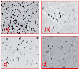 | Reproduce with permission from Ref. [40]. Copyrights 2019 Elsevier. |
| Ti Spherical | - | 231–551 | 6.6–55.6 | (a) 800 (b) 900 (c) 1000 (d) 1200 | 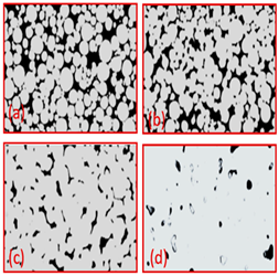 | Reproduce with permission from Ref. [41]. Copyrights 2019 Wiley onine library. |
| Ti (HDH) | - | 231–551 | 6.6–55.6 | (a) 800 (b) 900 (c) 1000 (d) 1200 | 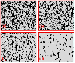 | Reproduce with permission from Ref. [41]. Copyrights 2019 Wiley online library. |
| Ti64 | - | 370 | 36.2 | 1000 | 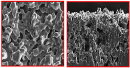 | Reproduce with permission from Ref. [42]. Copyrights 2006 Elsevier |
| Material | Factor | Effect on Pores Morphology | Ref |
|---|---|---|---|
| TiO2 | Binder (a) 3 wt % PVA (cross-section parallel to ice growth) (a) 3 wt % PVA (cross-section Perpendicular to ice growth) (c) 6 wt % PVA (cross-section parallel to ice growth) (d) 6 wt % PVA (cross-section Perpendicular to ice growth) | 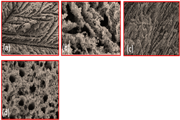 | Reproduced with permission from Ref. [56]. Copyrights 2009 Elsevier |
| Alumina | Solid loading (a) 45% (b) 50% (c) 55% (d) 57.5% (e) 60% | 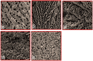 | Reproduced with permission from Ref. [57]. Copyrights 2004 John Wiley |
| Hydroxyapatite | Solvent composition (a) Water (b) Water + 20% glycerol (c) Water + 60% glycerol | 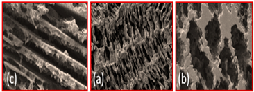 | Reproduced with permission from Ref. [58]. Copyrights 2008 IOP Science |
| Hydroxyapatite/tri calcium phosphate (HA/TCP) ceramic | Freezing Temperature (a) 4 °C (b) 23 °C (c) 30 °C | 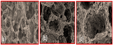 | Reproduced with permission from Ref. [59]. Copyrights 2009 Elsevier |
| Al2O3 | Freezing rate (a) 1 °C/min (b) 0.5 °C/min (c) 0.25 °C/min (d) 0.05 °C/min |  | Reproduced with permission from Ref. [60]. Copyrights 2010 Springer |
| Pore Agent | Porosity Range (%) | Pore Size (μm) |
|---|---|---|
| NaCl | 65–90 | 200–750 |
| Carbimide | 40–85 | 750–5000 |
| Sacchrose | 50–75 | 125–2000 |
| Pore Agent | Porosity Range (%) | Pore Size (μm) |
|---|---|---|
| Polymethyl methacrylate | 5–60 | 10–50 |
| NH4HCO3 | - | 150–600 |
| Saccharose | 82 | 85–2000 |
| Pore Agent | Porosity Range (%) | Pore Size (μm) |
|---|---|---|
| Magnesium | 51–65 | 375 |
| Ice | 57–67 | 50–170 |
| Method | Material | Pore Agent | Porosity | Pore Shape | Compressive Strength (MPa) |
|---|---|---|---|---|---|
| Sintering dissolution process | Titanium | Carbamide | 44 | Spherical Angular Needle-like | 185 175 140 |
| Thermally stimulated decomposition | Titanium Ti-15Mo | NH4HCO3 | 78 7.8 29.7 62.5 | Spherical Spherical | 35 1166 360 82 |
| Thermally melted elimination | TiNi | Magnesium | 49 58 64 | Spherical | 264.2–282.7 164–185.5 87.97–98.87 |
| Method | Porosity Controller | GDL Thickness Range | Basic Material |
|---|---|---|---|
| Tape casting | Sintering temp | 100–2000 μm | Slurry |
| 3D printing | Design of the 3D model | Micro size | Powder |
| Freeze casting | Ice | Micro and macro | Slurry |
| Phase separation technique | Pore agent | Micro and above | Only powder |
| Photolithography | Etching time and mask width | Micro to nano size | Photoresist filament |
| SV | Ksim × 10−11 (m2) | MREexp/sim (%) Kexp = 3.36 × 10⁻¹¹ m2 |
|---|---|---|
| 1 | 3.25 | 3.2 |
| 2 | 3.44 | 2.3 |
| 3 | 3.27 | 2.7 |
| Mean | 3.26 | 4.2 |
Disclaimer/Publisher’s Note: The statements, opinions and data contained in all publications are solely those of the individual author(s) and contributor(s) and not of MDPI and/or the editor(s). MDPI and/or the editor(s) disclaim responsibility for any injury to people or property resulting from any ideas, methods, instructions or products referred to in the content. |
© 2023 by the authors. Licensee MDPI, Basel, Switzerland. This article is an open access article distributed under the terms and conditions of the Creative Commons Attribution (CC BY) license (https://creativecommons.org/licenses/by/4.0/).
Share and Cite
Hussain, J.; Kim, D.-K.; Park, S.; Khalid, M.-W.; Hussain, S.-S.; Lee, B.; Song, M.; Kim, T.-S. Porous Material (Titanium Gas Diffusion Layer) in Proton Exchange Membrane Fuel Cell/Electrolyzer: Fabrication Methods & GeoDict: A Critical Review. Materials 2023, 16, 4515. https://doi.org/10.3390/ma16134515
Hussain J, Kim D-K, Park S, Khalid M-W, Hussain S-S, Lee B, Song M, Kim T-S. Porous Material (Titanium Gas Diffusion Layer) in Proton Exchange Membrane Fuel Cell/Electrolyzer: Fabrication Methods & GeoDict: A Critical Review. Materials. 2023; 16(13):4515. https://doi.org/10.3390/ma16134515
Chicago/Turabian StyleHussain, Javid, Dae-Kyeom Kim, Sangmin Park, Muhammad-Waqas Khalid, Sayed-Sajid Hussain, Bin Lee, Myungsuk Song, and Taek-Soo Kim. 2023. "Porous Material (Titanium Gas Diffusion Layer) in Proton Exchange Membrane Fuel Cell/Electrolyzer: Fabrication Methods & GeoDict: A Critical Review" Materials 16, no. 13: 4515. https://doi.org/10.3390/ma16134515