
Changes in the Strength and Leaching Characteristics of Steel Slag-Oil Shale Residue-Based Filling Paste in a Complex Erosive Environment

Abstract
:1. Introduction
2. Materials and Methods
2.1. Materials
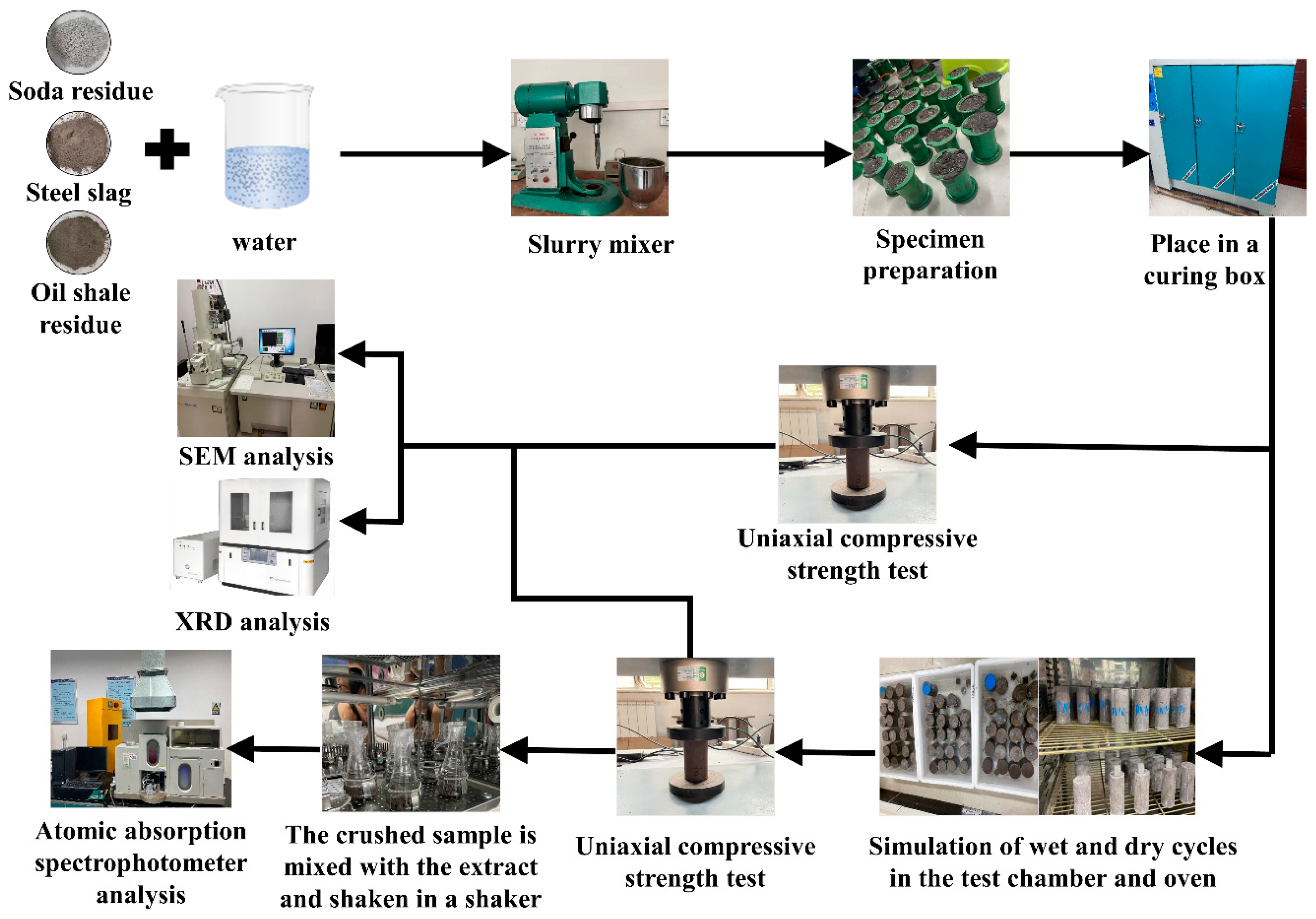
2.2. Methods
2.2.1. Preparation and Curing
2.2.2. Combined Chloride and Wet–Dry Cycles Erosion Test
2.2.3. Uniaxial Compressive Strength Test
2.2.4. Toxic Substance Leaching Test
2.2.5. Microscopic Analysis
3. Results and Discussion
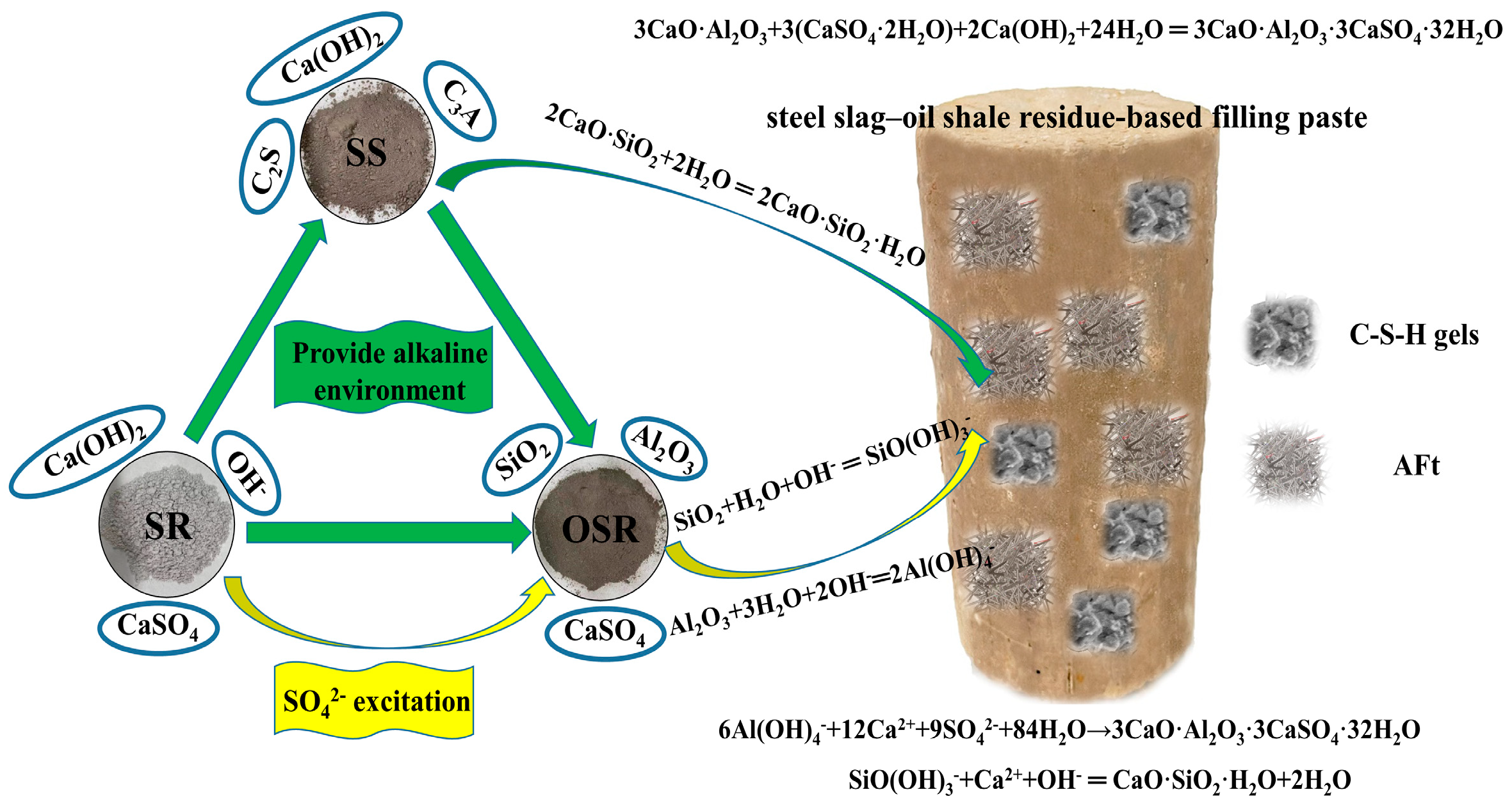
3.1. Synergies among Solid Waste
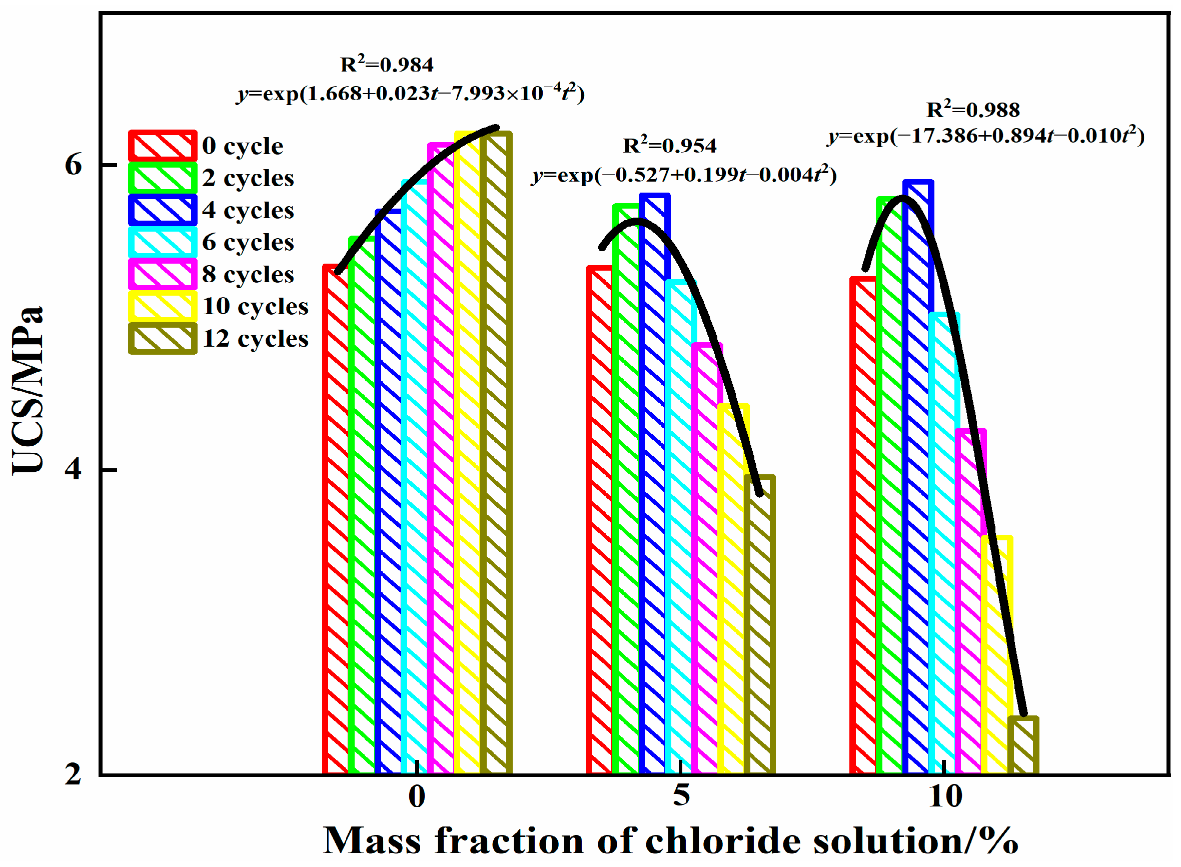
3.2. Analysis of Compressive Strength
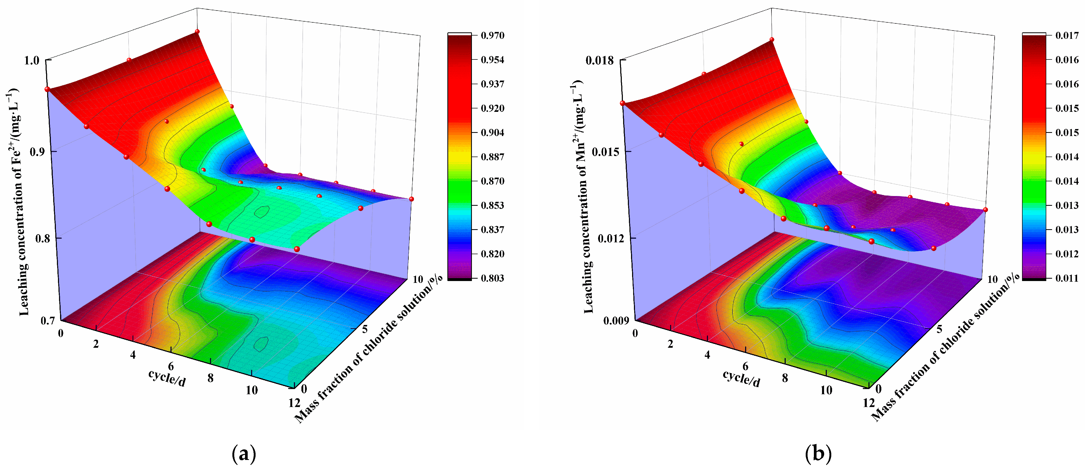
3.3. Analysis of Leaching Characteristics
3.4. Microscopic Characterization
3.4.1. Phase Composition of Steel Slag–Oil Shale Residue-Based Filling Paste
3.4.2. Microstructure of Steel Slag–Oil Shale Residue-Based Filling Paste
4. Analysis and Discussion
4.1. Effect of Chloride and Wet–Dry Cycling-Driven Erosion on the Strength of Steel Slag–Oil Shale Residue-Based Filling Paste
4.2. Effect of Erosion under the Combined Action of Chloride and Wet–Dry Cycling on the Leaching Characteristics of Steel Slag–Oil Shale Residue-Based Filling Paste
5. Conclusions
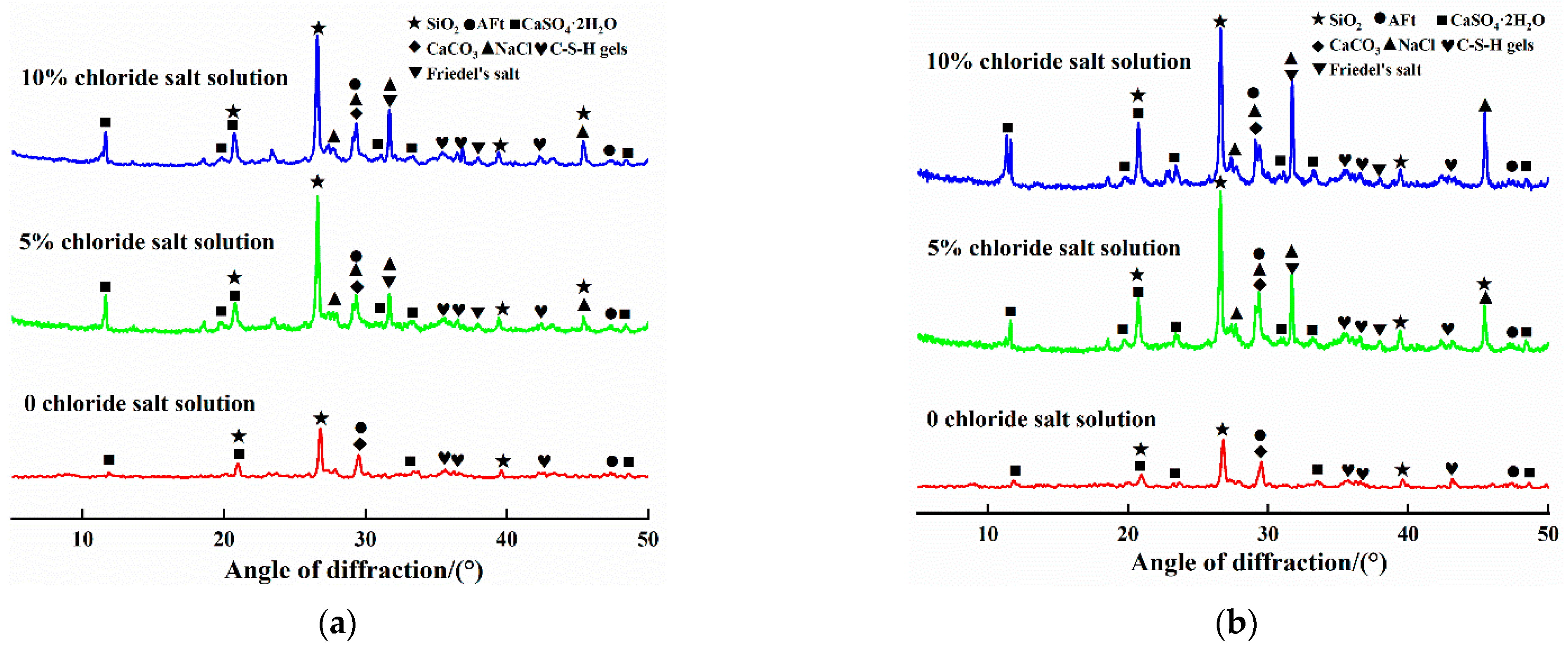
- The influence of the mass fraction of chloride in the solution and the number of cycles on the uniaxial compressive strength of steel slag–oil shale residue-based filling paste is obvious. Within 12 cycles, AFt and C-S-H gels increased in the aqueous solution with 0% chloride, resulting in gradual internal compactness and increased compressive strength. When the specimen was immersed in 5% and 10% chloride salt solutions, Friedel’s salt was generated due to erosion by Cl− in the early stages of cycling, which filled internal pores, increased compressive strength and resulted in peak strength values. With an increase in the number of cycles, large amounts of hydration products accumulated in the specimen in the later stage, resulting in the formation of local cracks and decreasing compressive strength. The compressive strength of the specimen had an exponential relationship with the cycling period.
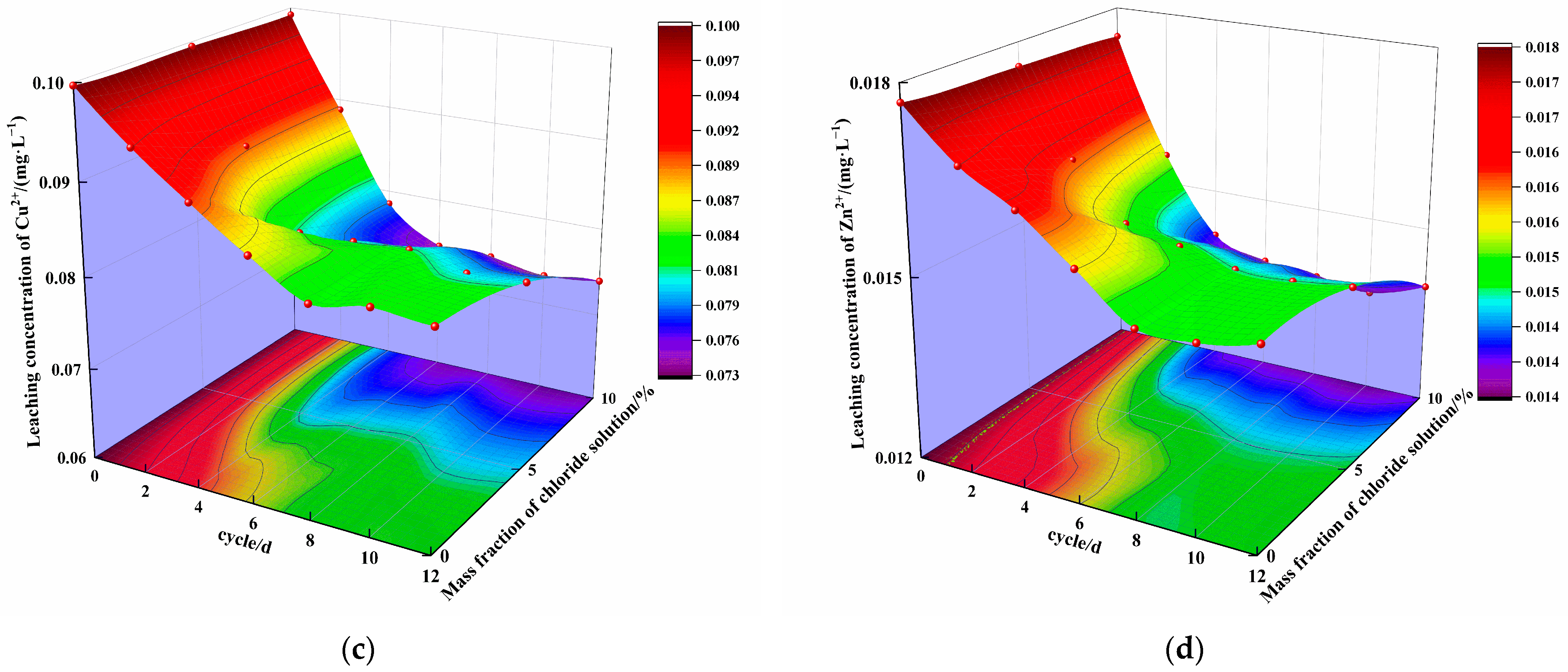
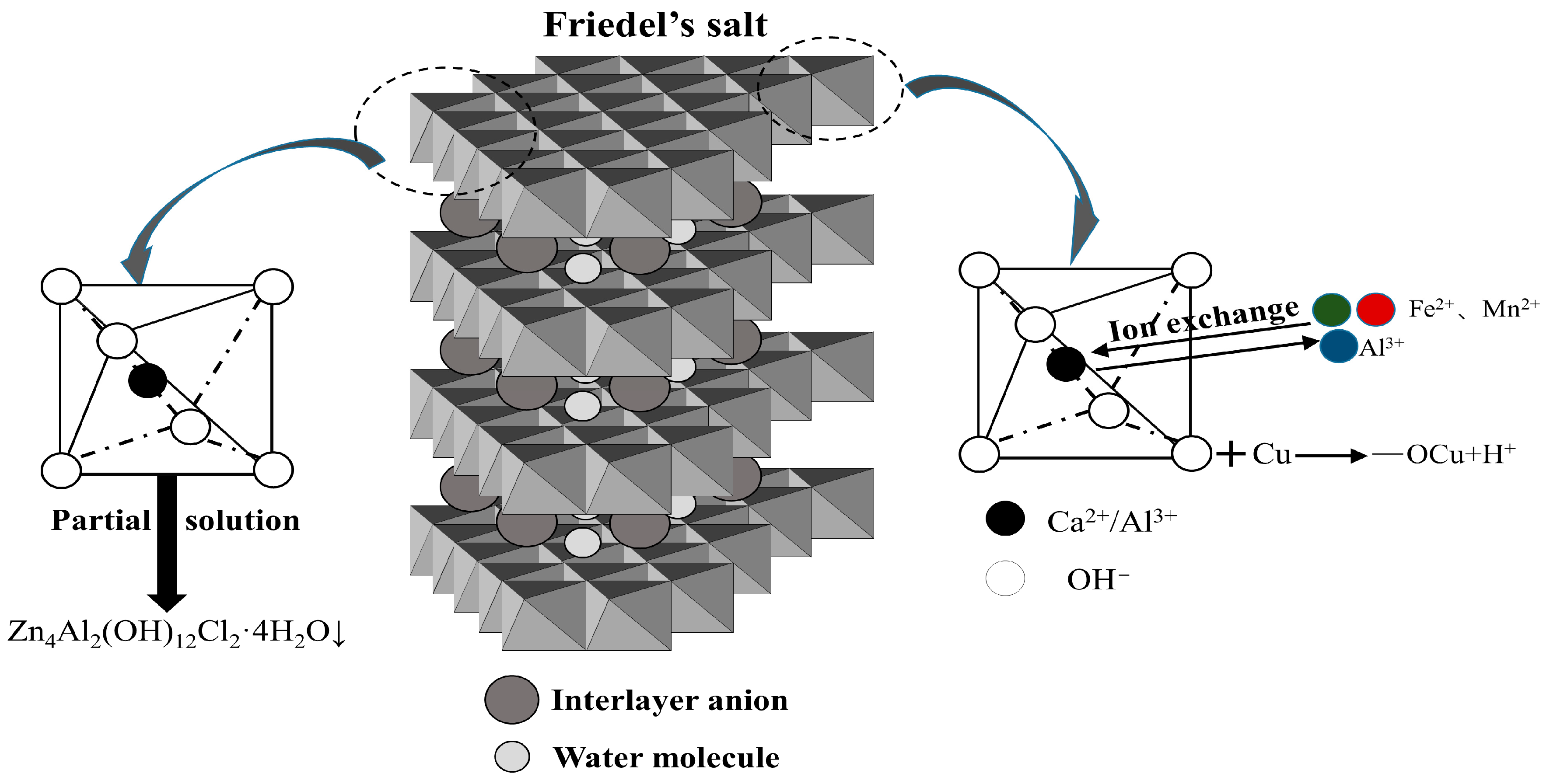
- Over 12 cycles, the concentration of ions in the specimen leaching solution with 0% chloride first slowly decreased and then tended to remain stable, while the concentration of ions in the specimen leaching solution with mass fractions of 5% and 10% chloride salt first rapidly decreased and then tended to remain stable. Under the same cycling conditions, the concentration of ions in the leaching solution decreased with increasing mass fraction of chloride in the solution. The leached concentration of all ions decreased compared with the initial concentration. The number of cycles and the mass fraction of chloride affect the type and quantity of erosion products, playing a role in curing heavy metal ions.
- Ca(OH)2 in the steel slag–oil shale residue-based filling paste is provided by steel slag and soda residue. The alkaline environment created by steel slag and soda residue enables SiO2 and Al2O3 in the oil shale residue to carry out continuous hydration reactions, and a large amount of Ca(OH)2 is consumed in the hydration stage. However, with an increase in the number of dry–wet cycles and due to continuous immersion in chloride salts, the hydration reactions of the traditional cement-based filling materials progress adequately, and an increasing amount of Ca(OH)2 is generated. This indicates that the steel slag–oil shale residue-based filling paste has stronger chloride resistance than traditional cement-based filling pastes.
Author Contributions
Funding
Institutional Review Board Statement
Informed Consent Statement
Data Availability Statement
Conflicts of Interest
References
- Cao, S.; Song, W.; Xue, G.; Ma, R.; Zhu, P. Mechanical characteristics variation of stratified cemented tailing backfilling and its failure modes. J. China Univ. Min. Technol. 2016, 45, 717–722, 728. [Google Scholar] [CrossRef]
- Liu, L.; Wang, S.; Zhu, M.; Zhang, B.; Hou, D.; Xun, C.; Zhao, Y.; Zhang, X.; Wang, X.; Wang, M. CO2 storage-cavern construction and storage method based on functional backfill. J. China Coal Soc. 2022, 47, 1072–1086. [Google Scholar] [CrossRef]
- Liu, S.; Wang, F.; Li, G.; Liu, G.; Wang, J.; Qi, Z. Optimization of mixture ratio and microstructure influence mechanism of composite filling slurry based on response surface method. Acta Mater. Compos. Sin. 2021, 38, 2724–2736. [Google Scholar] [CrossRef]
- Lan, W.; Wu, A.; Wang, Y. Formulation optimization and formation mechanism of condensate expansion and filling composites. Acta Mater. Compos. Sin. 2019, 36, 1536–1545. [Google Scholar] [CrossRef]
- Zhao, K.; He, Z.; Ning, F.; Zhou, Y.; Yan, Y.; Wang, Y.; Wang, J. Acoustic emission characteristics of cementitious material with different cement-tailing ratio. J. Chin. Ceram. Soc. 2021, 49, 2462–2469. [Google Scholar] [CrossRef]
- Ruan, Z.; Wu, A.; Wang, Y.; Wang, S.; Wang, J. Multiple response optimization of key performance indicators of cemented paste backfill of total solid waste. Chin. J. Eng. 2022, 44, 496–503. [Google Scholar] [CrossRef]
- Li, B.; Yin, H.; Mao, X.; Li, Y.; Zhang, L.; Liu, R.; Qiu, P. Macroscopic and microscopic fracture features of concrete used in coal mine under chlorine salt erosion. Int. J. Min. Sci. Technol. 2016, 26, 455–459. [Google Scholar] [CrossRef]
- Sun, Q.; Li, X.; Wei, X.; Mu, Q. Experimental study of the influence of chloride corrosion on creep properties of filling paste. J. Exp. Mech. 2015, 30, 231–238. [Google Scholar]
- Ma, D.; Kong, S.; Li, Z.; Zhang, Q.; Wang, Z.; Zhou, Z. Effect of wetting-drying cycle on hydraulic and mechanical properties of cemented paste backfill of the recycled solid wastes. Chemosphere 2021, 282, 131163. [Google Scholar] [CrossRef]
- Du, Z.; Chen, S.; Yin, D.; Yao, D.; Zhang, Z. Experimental study of stability of paste backfill under chloride erosion environment. J. China Univ. Min. Technol. 2021, 50, 532–538, 547. [Google Scholar] [CrossRef]
- Zhou, X.; Liu, C.; Feng, B.; Guo, B.; Lu, Y.; Zhang, L. Effects of dry-wet circulation on cement-based composite filling materials. Chin. J. Eng. 2019, 41, 1609–1617. [Google Scholar] [CrossRef]
- Wang, S.; Wang, F.; Yin, D.; Jiang, T.; Zhang, Z. Experimental Study on Mechanical Properties of Paste Backfill with Flue-Gas Desulphurisation Gypsum under Combined Action of Dry–Wet Cycles and Chloride Erosion. Minerals 2021, 11, 882. [Google Scholar] [CrossRef]
- Liu, H.; Zhang, J.; Zhou, N.; Shen, L.; Zhang, L.; Zhu, C.; Wang, L. Study of the leaching and solidification mechanism of heavy metals from gangue-based cemented paste backfilling materials. J. China Univ. Min. Technol. 2021, 50, 523–531. [Google Scholar] [CrossRef]
- Chen, Q.; Zhang, Q.; Qi, C.; Zhang, Q.; Feng, Y.; Wang, D.; Tao, Y.; Lu, R. Temperature-depending characteristics of strength and leaching toxicity of phosphogympsum-based cemented paste backfill. Chin. J. Nonferrous Met. 2021, 31, 1084–1095. [Google Scholar]
- Mahedi, M.; Cetin, B. Leaching of elements from cement activated fly ash and slag amended soils. Chemosphere 2021, 31, 1084–1095. [Google Scholar] [CrossRef]
- Yang, H.; Ni, W.; Zhang, S.; Ma, X. Mechanisms of solidification of cadmium in municipal solid waste incineration fly ash usinga slag cemented backfill agent. Chin. J. Eng. 2018, 40, 1027–1035. [Google Scholar] [CrossRef]
- Li, K.; Li, X.; Du, C.; Xue, H.; Sun, Q.; Liu, L. Experimental study on microstructure and erosion mechanisms of solid waste cemented paste backfill under the combined action of dry–wet cycles and sulphate erosion. Materials 2022, 15, 1484. [Google Scholar] [CrossRef]
- Zhang, H.; Yang, Y.; Yi, Y. Effect of sulfate erosion on strength and leaching characteristic of stabilized heavy metal contaminated red clay. Trans. Nonferrous Met. Soc. China 2017, 27, 666–675. [Google Scholar] [CrossRef]
- Zha, F.; Liu, J.; Xu, L.; Cui, K. Cyclic wetting and drying tests on heavy metal contaminated soils solidified/stabilized by cement. Chin. J. Geotech. Eng. 2013, 35, 1246–1252. [Google Scholar]
- Malliou, O.; Katsioti, M.; Georgiadis, A.; Katsiri, A. Properties of stabilized/solidified admixtures of cement and sewage sludge. Cem. Concr. Compos. 2007, 29, 55–61. [Google Scholar] [CrossRef]
- Zhang, J. Study on Synthesis, Characterization of Ca-Based Functional Materials and Their Adsorption of Heavy Metal Ions. Master’s Thesis, Changsha University of Science & Technology, Changsha, China, 2013. [Google Scholar]
- Xia, Z.; Wang, M.; Wang, F.; Shang, D. Formation process of interstitials containing manganese and its solidification. J. Chin. Ceram. Soc. 2017, 45, 614–622. [Google Scholar] [CrossRef]
- Wang, X.; Wang, Q.; Zhang, B.; Ni, W.; Jin, R.; Zhao, K. Hydration mechanism of using steel slag as binder for backfill materials in potash mines. Chin. J. Eng. 2018, 40, 1177–1186. [Google Scholar] [CrossRef]
- Liu, Q.; Li, Y.; Zhang, J.; Chi, Y.; Ruan, X.; Liu, J.; Qian, G. Effective removal of zinc from aqueous solution by hydrocalumite. Chem. Eng. J. 2011, 175, 33–38. [Google Scholar] [CrossRef]
- Park, M.; Choi, C.; Seo, Y.; Yeo, S.; Choi, J.; Komarneni, S.; Lee, J. Reactions of Cu2+ and Pb2+ with Mg/Al layered double hydroxide. Appl. Clay Sci. 2007, 37, 143–148. [Google Scholar] [CrossRef]
- Bothe, J.; Brown, P. PhreeqC modeling of Friedel’s salt equilibria at 23 ± 1 °C. Cem. Concr. Res. 2004, 34, 1057–1063. [Google Scholar] [CrossRef]
- Qian, G.; Cao, Y.; Chui, P.; Tay, J. Utilization of MSWI fly ash for stabilization/solidification of industrial waste sludge. J. Hazard. Mater. 2006, 129, 274–281. [Google Scholar] [CrossRef]
- Mijno, V.; Catalan, L.; Martin, F.; Bollinger, J. Compositional changes in cement-stabilized waste during leach tests-comparison of SEM/EDX data with predictions from geochemical speciation modeling. J. Colloid Interface Sci. 2004, 280, 465–477. [Google Scholar] [CrossRef]


| Materials | Al2O3 | CaO | SiO2 | Fe2O3 | MgO | SO3 | Na2O | TiO2 | K2O | MnO | P2O5 | Cl |
|---|---|---|---|---|---|---|---|---|---|---|---|---|
| Steel slag | 6.15 | 40.75 | 12.39 | 14.17 | 21.21 | 2.79 | 0.03 | 0.81 | 0.15 | 1.23 | — | — |
| Oil shale residue | 14.71 | 7.15 | 62.16 | 8.32 | 2.38 | 0.82 | 0.04 | 0.87 | 3.07 | 0.24 | — | — |
| Soda residue | 4.31 | 66.12 | 9.68 | 0.29 | 0.31 | 11.21 | 1.99 | 0.22 | 1.32 | — | 0.18 | 2.62 |
| Ions | Fe2+ | Mn2+ | Cu2+ | Zn2+ |
|---|---|---|---|---|
| Steel slag | 1.503 | 0.123 | 0.231 | 0.154 |
| Oil shale residue | 1.111 | 0.087 | 0.101 | 0.077 |
| Soda residue | 0.455 | 0.048 | 0.012 | 0.012 |
Disclaimer/Publisher’s Note: The statements, opinions and data contained in all publications are solely those of the individual author(s) and contributor(s) and not of MDPI and/or the editor(s). MDPI and/or the editor(s) disclaim responsibility for any injury to people or property resulting from any ideas, methods, instructions or products referred to in the content. |
© 2023 by the authors. Licensee MDPI, Basel, Switzerland. This article is an open access article distributed under the terms and conditions of the Creative Commons Attribution (CC BY) license (https://creativecommons.org/licenses/by/4.0/).
Share and Cite
Lian, F.; Du, C.; Meng, D. Changes in the Strength and Leaching Characteristics of Steel Slag-Oil Shale Residue-Based Filling Paste in a Complex Erosive Environment. Materials 2023, 16, 4593. https://doi.org/10.3390/ma16134593
Lian F, Du C, Meng D. Changes in the Strength and Leaching Characteristics of Steel Slag-Oil Shale Residue-Based Filling Paste in a Complex Erosive Environment. Materials. 2023; 16(13):4593. https://doi.org/10.3390/ma16134593
Chicago/Turabian StyleLian, Fengmei, Chuanyang Du, and Dan Meng. 2023. "Changes in the Strength and Leaching Characteristics of Steel Slag-Oil Shale Residue-Based Filling Paste in a Complex Erosive Environment" Materials 16, no. 13: 4593. https://doi.org/10.3390/ma16134593
APA StyleLian, F., Du, C., & Meng, D. (2023). Changes in the Strength and Leaching Characteristics of Steel Slag-Oil Shale Residue-Based Filling Paste in a Complex Erosive Environment. Materials, 16(13), 4593. https://doi.org/10.3390/ma16134593