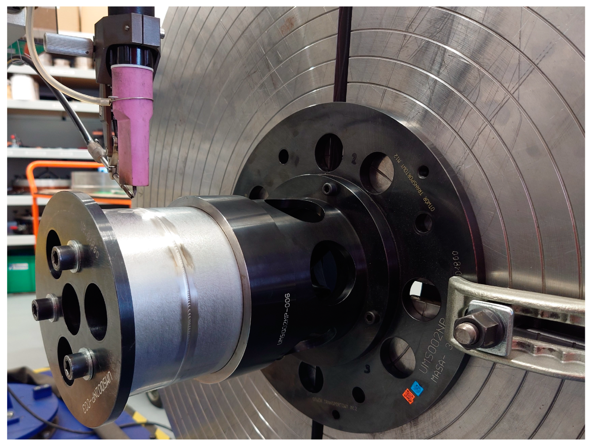
Figure 1.
Bench for automated TIG welding of thin-walled components made of 17-4 PH steel.
Figure 1.
Bench for automated TIG welding of thin-walled components made of 17-4 PH steel.
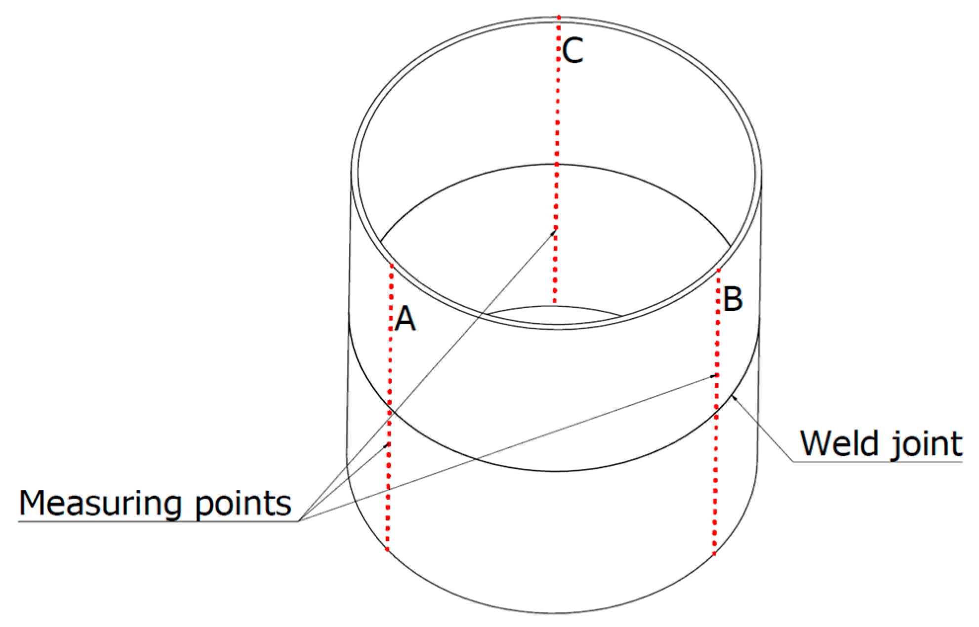
Figure 2.
Diagram of the distribution of measurement points.
Figure 2.
Diagram of the distribution of measurement points.
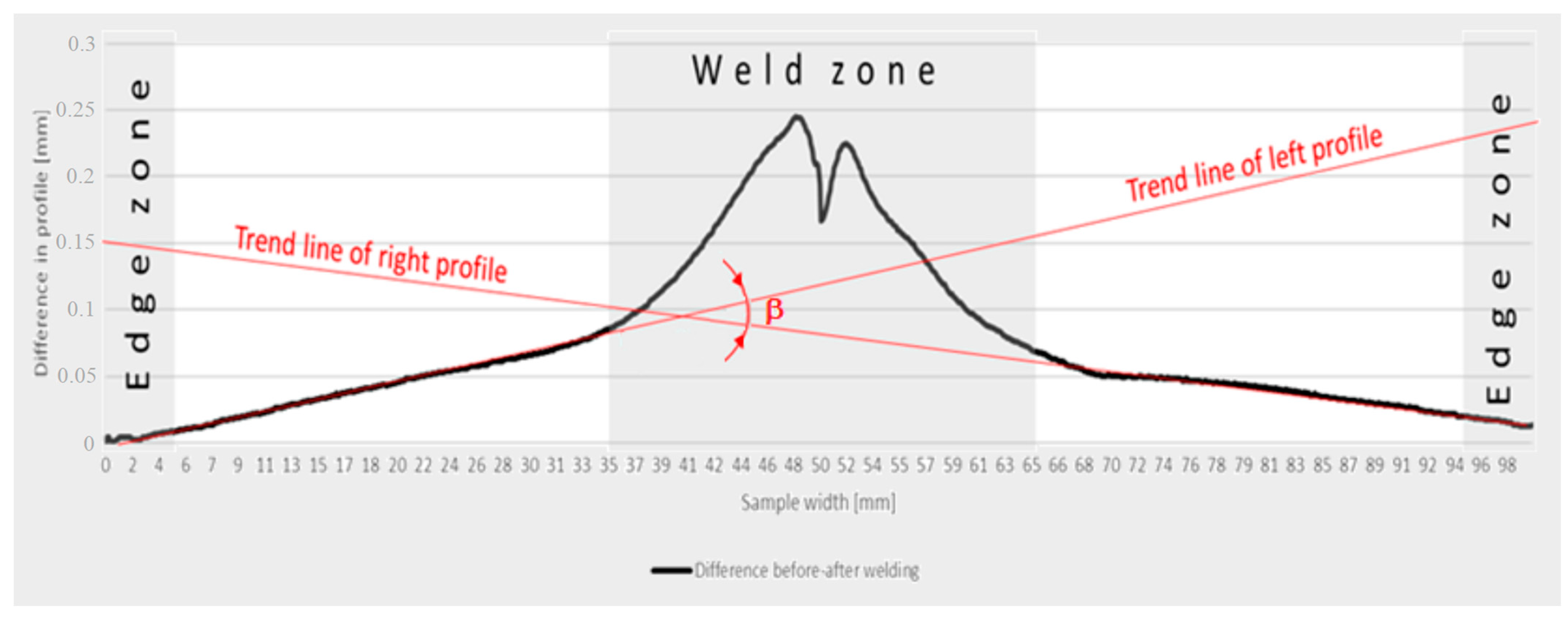
Figure 3.
Methodology for calculating angular strain values.
Figure 3.
Methodology for calculating angular strain values.
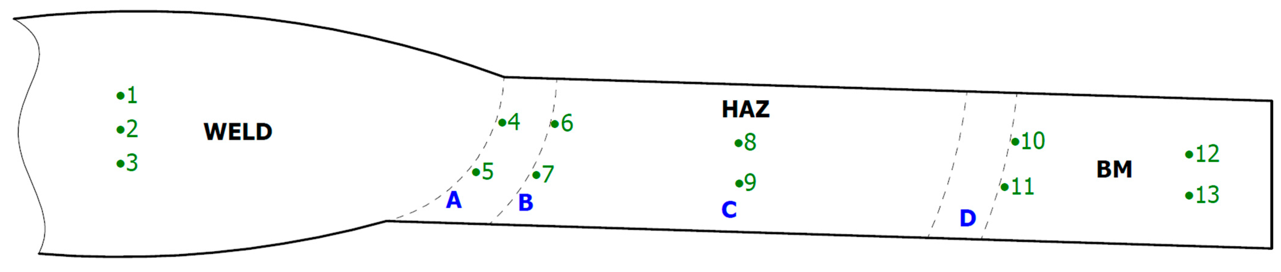
Figure 4.
Scheme of hardness measurements of test welded joints manually and automatically.
Figure 4.
Scheme of hardness measurements of test welded joints manually and automatically.
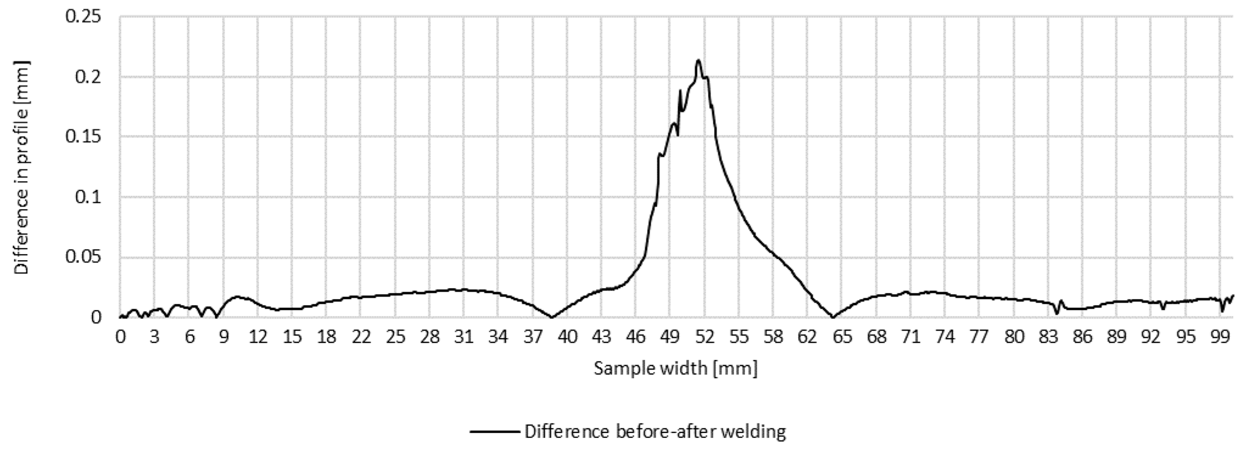
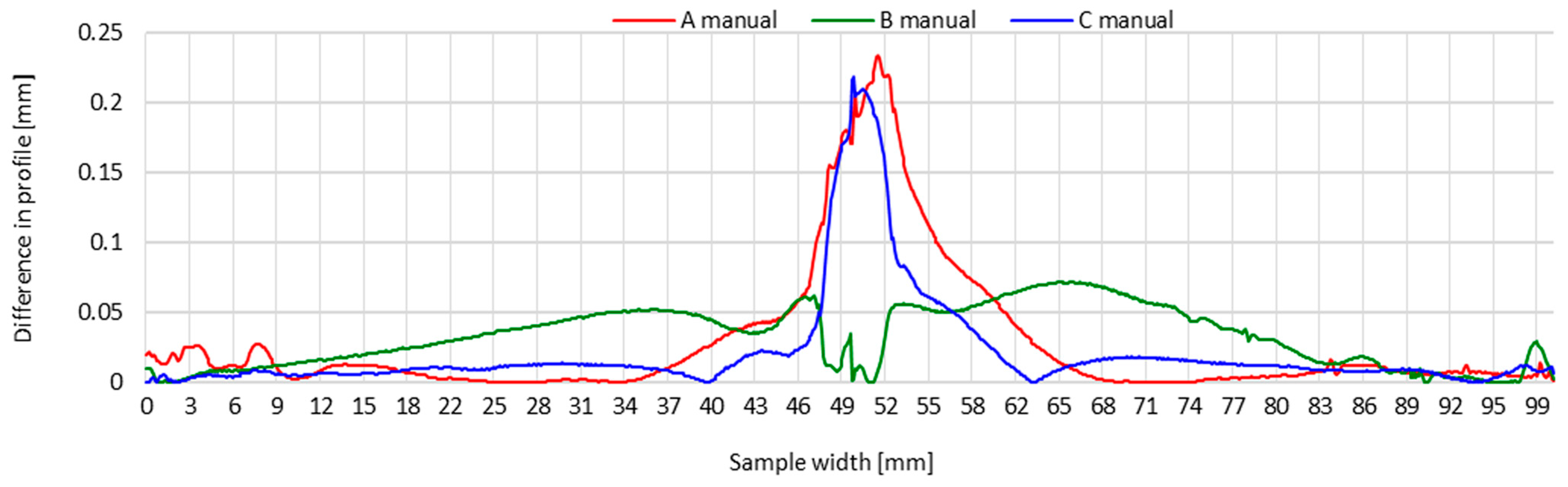
Figure 5.
Difference in transverse profiles on line A before and after manual welding.
Figure 5.
Difference in transverse profiles on line A before and after manual welding.
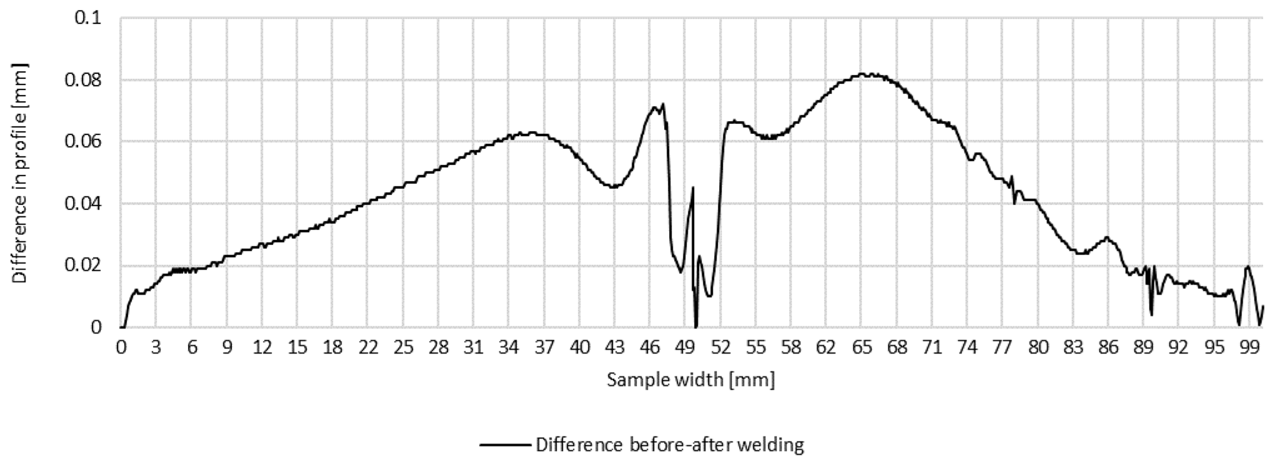
Figure 6.
Difference in transverse profiles on line B before and after manual welding.
Figure 6.
Difference in transverse profiles on line B before and after manual welding.
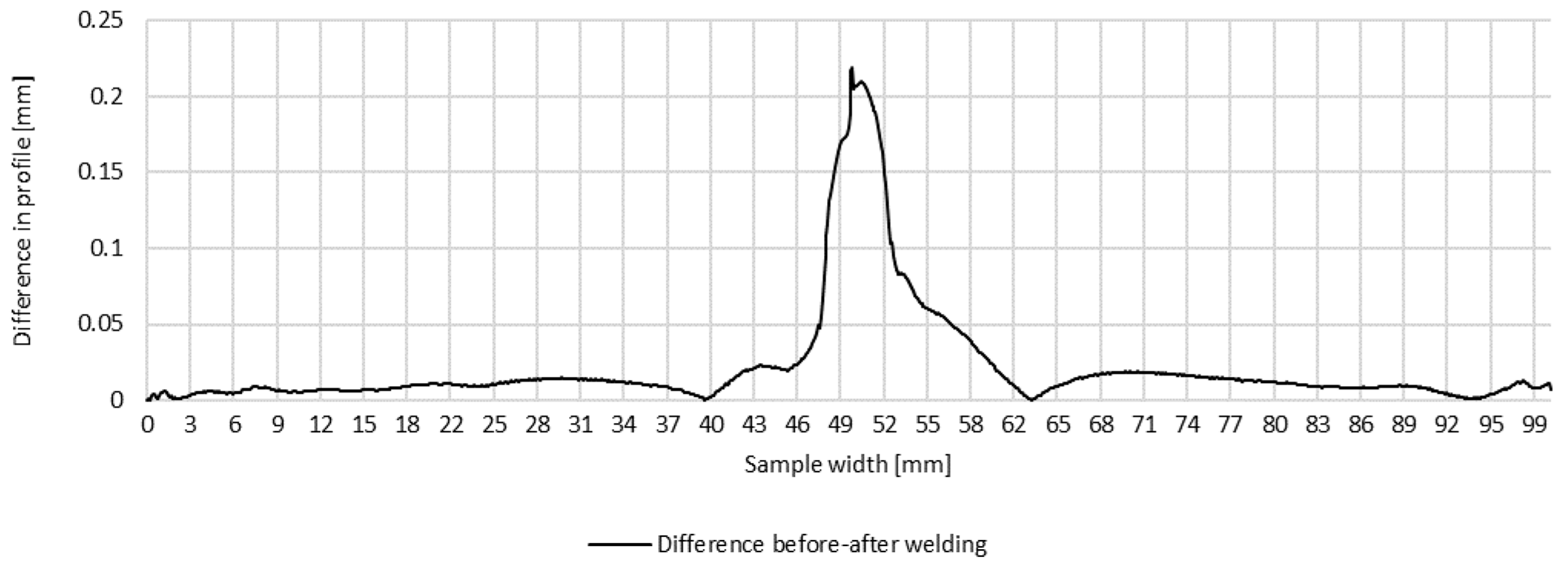
Figure 7.
Difference in transverse profiles on line C before and after manual welding.
Figure 7.
Difference in transverse profiles on line C before and after manual welding.
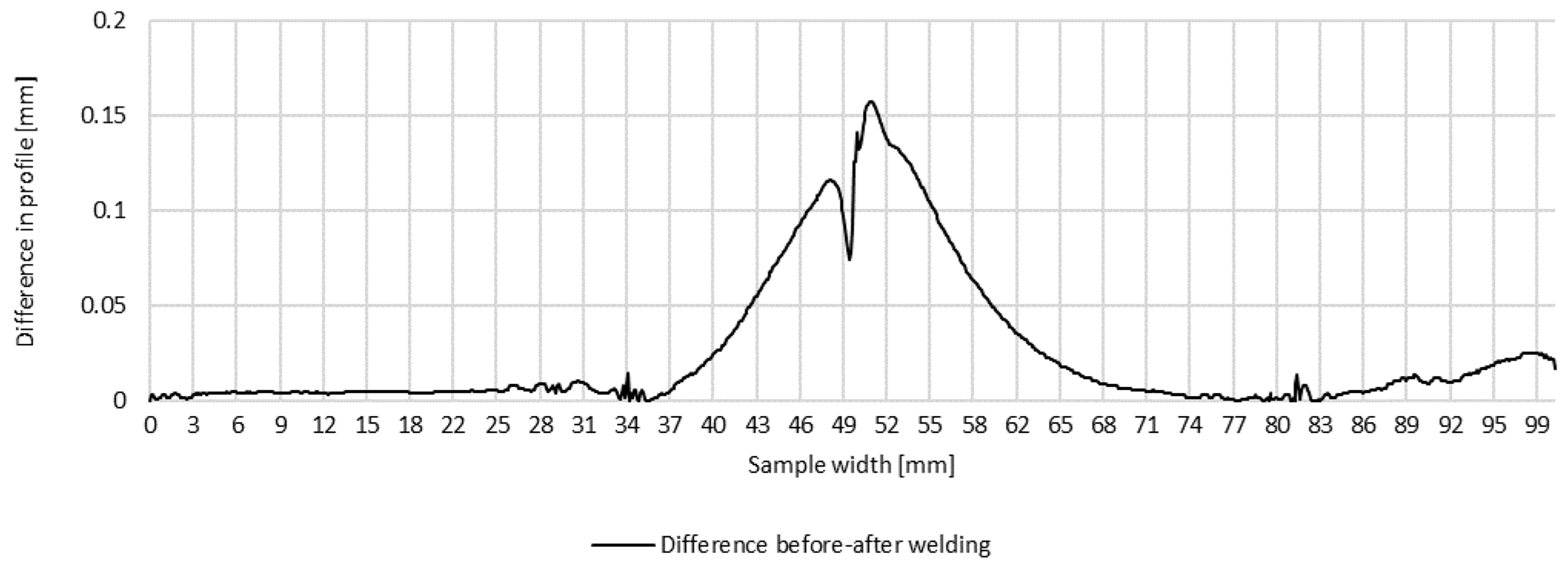
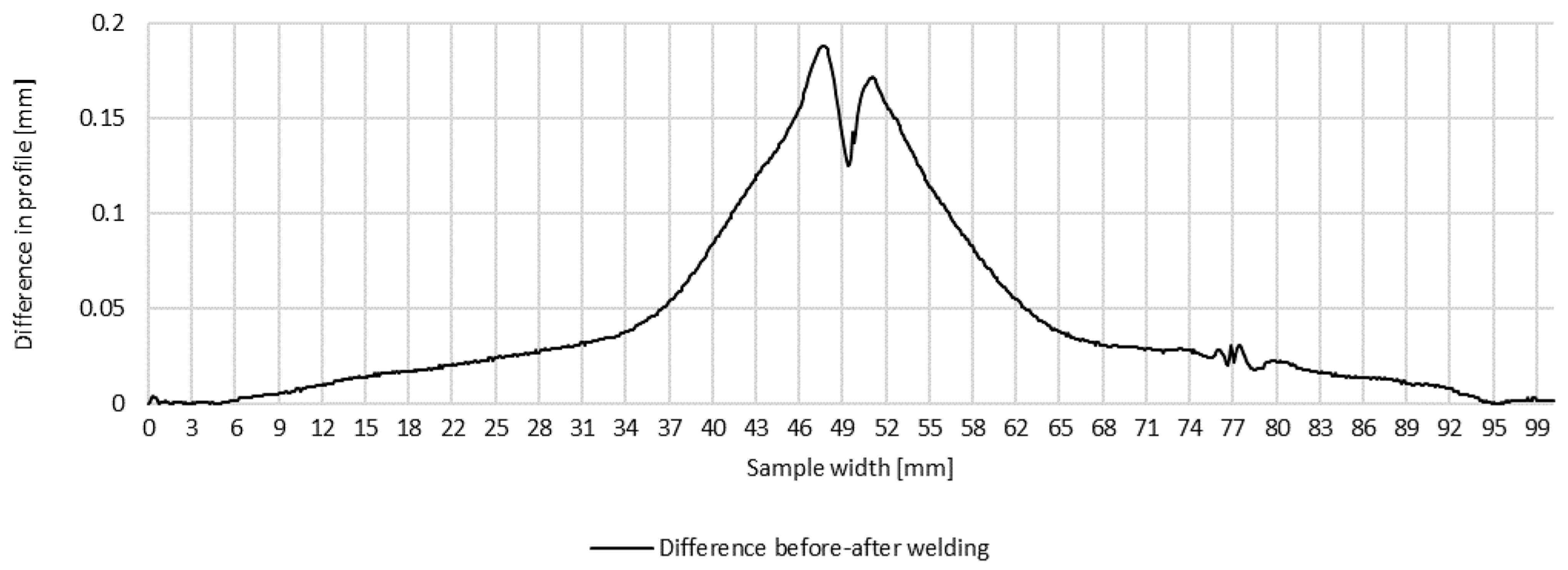
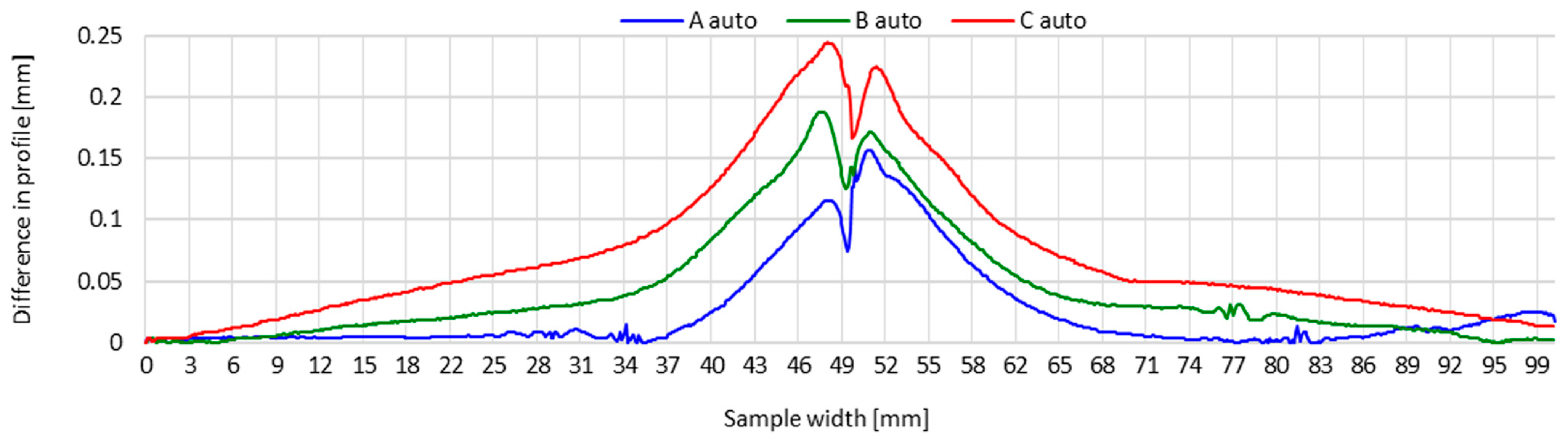
Figure 8.
Difference in transverse profiles on line A before and after automated welding.
Figure 8.
Difference in transverse profiles on line A before and after automated welding.
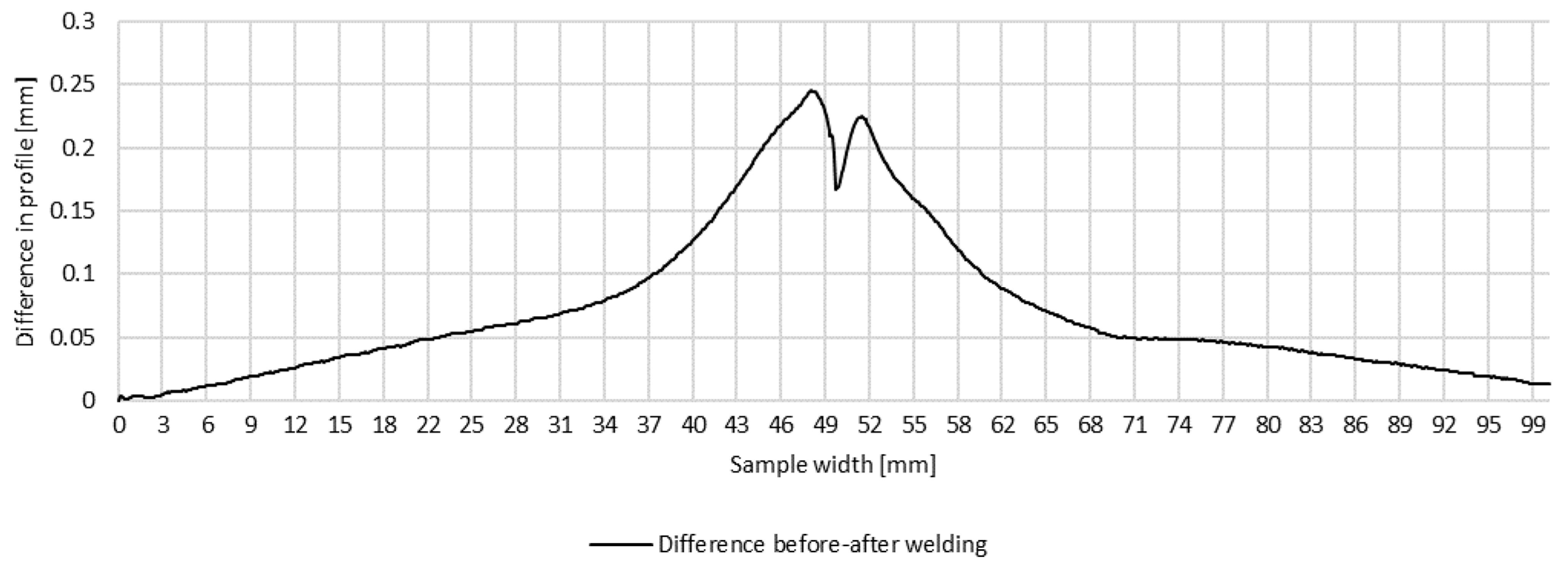
Figure 9.
Difference in transverse profiles on line B before and after automated welding.
Figure 9.
Difference in transverse profiles on line B before and after automated welding.
Figure 10.
Difference in transverse profiles on line C before and after automated welding.
Figure 10.
Difference in transverse profiles on line C before and after automated welding.
Figure 11.
Transverse profiles on lines A, B and C after making a test joint of thin-walled components of 17-4 PH steel—manual welding.
Figure 11.
Transverse profiles on lines A, B and C after making a test joint of thin-walled components of 17-4 PH steel—manual welding.
Figure 12.
Transverse profiles on lines A, B and C after making a test joint of thin-walled components of 17-4 PH steel—automated welding.
Figure 12.
Transverse profiles on lines A, B and C after making a test joint of thin-walled components of 17-4 PH steel—automated welding.
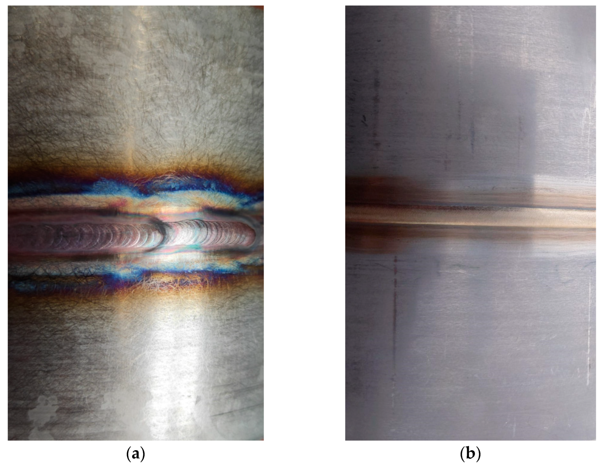
Figure 13.
Example view of the face of the test joint made manually (a) and by automated welding method (b).
Figure 13.
Example view of the face of the test joint made manually (a) and by automated welding method (b).
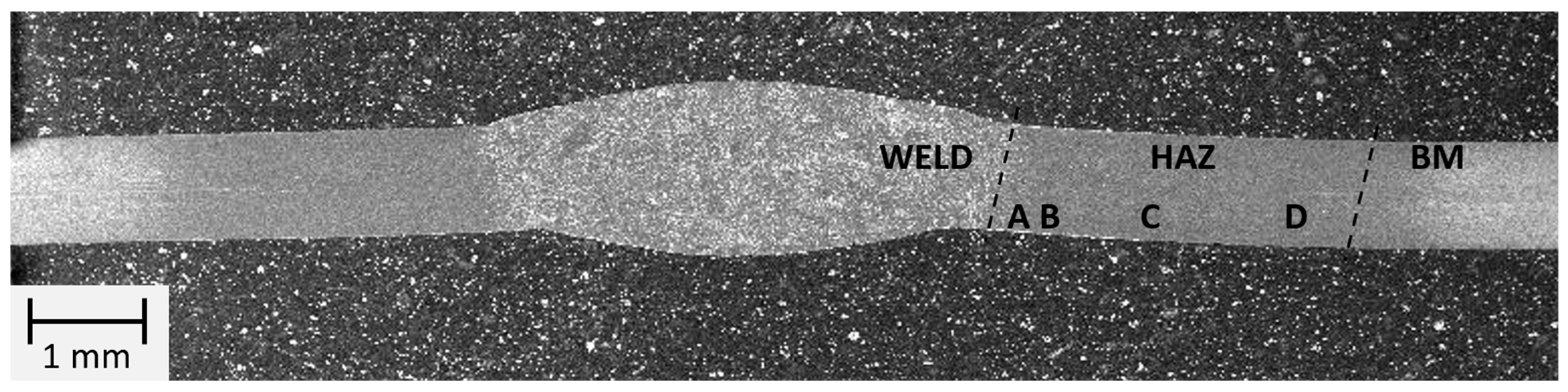
Figure 14.
Macrostructure of the welded joint area of thin-walled 17-4 PH steel components made manually by TIG method.
Figure 14.
Macrostructure of the welded joint area of thin-walled 17-4 PH steel components made manually by TIG method.
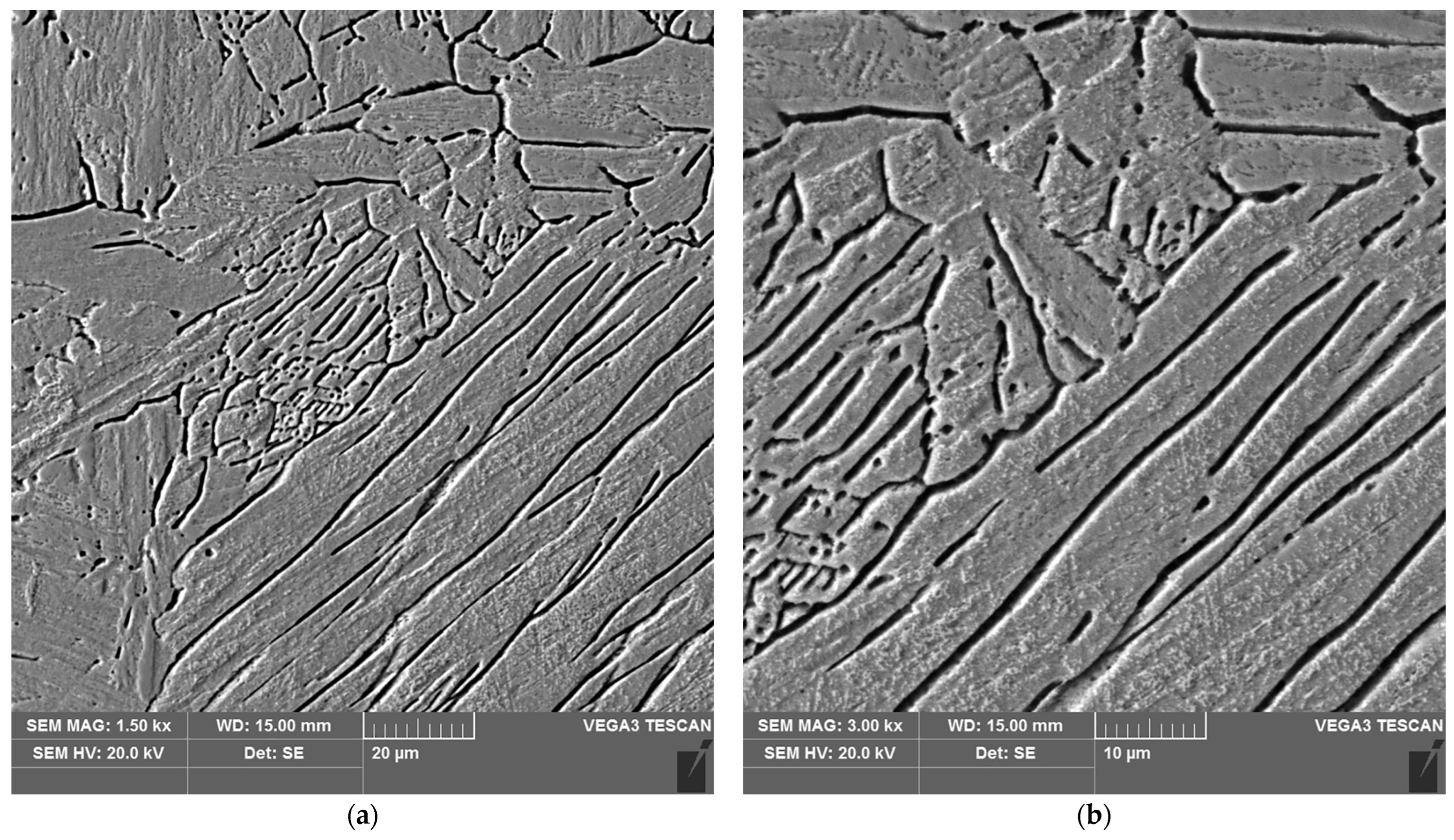
Figure 15.
Microstructure of the weld area of the test joint made manually: (a) magnification 1500×, (b) 3000×.
Figure 15.
Microstructure of the weld area of the test joint made manually: (a) magnification 1500×, (b) 3000×.
Figure 16.
Microstructure of the heat affected zone in area A of the test joint made manually: (a) magnification 1500×, (b) 3000×.
Figure 16.
Microstructure of the heat affected zone in area A of the test joint made manually: (a) magnification 1500×, (b) 3000×.
Figure 17.
Microstructure of the heat affected zone in area B of the test joint made manually: (a) magnification 1500×, (b) 3000×.
Figure 17.
Microstructure of the heat affected zone in area B of the test joint made manually: (a) magnification 1500×, (b) 3000×.
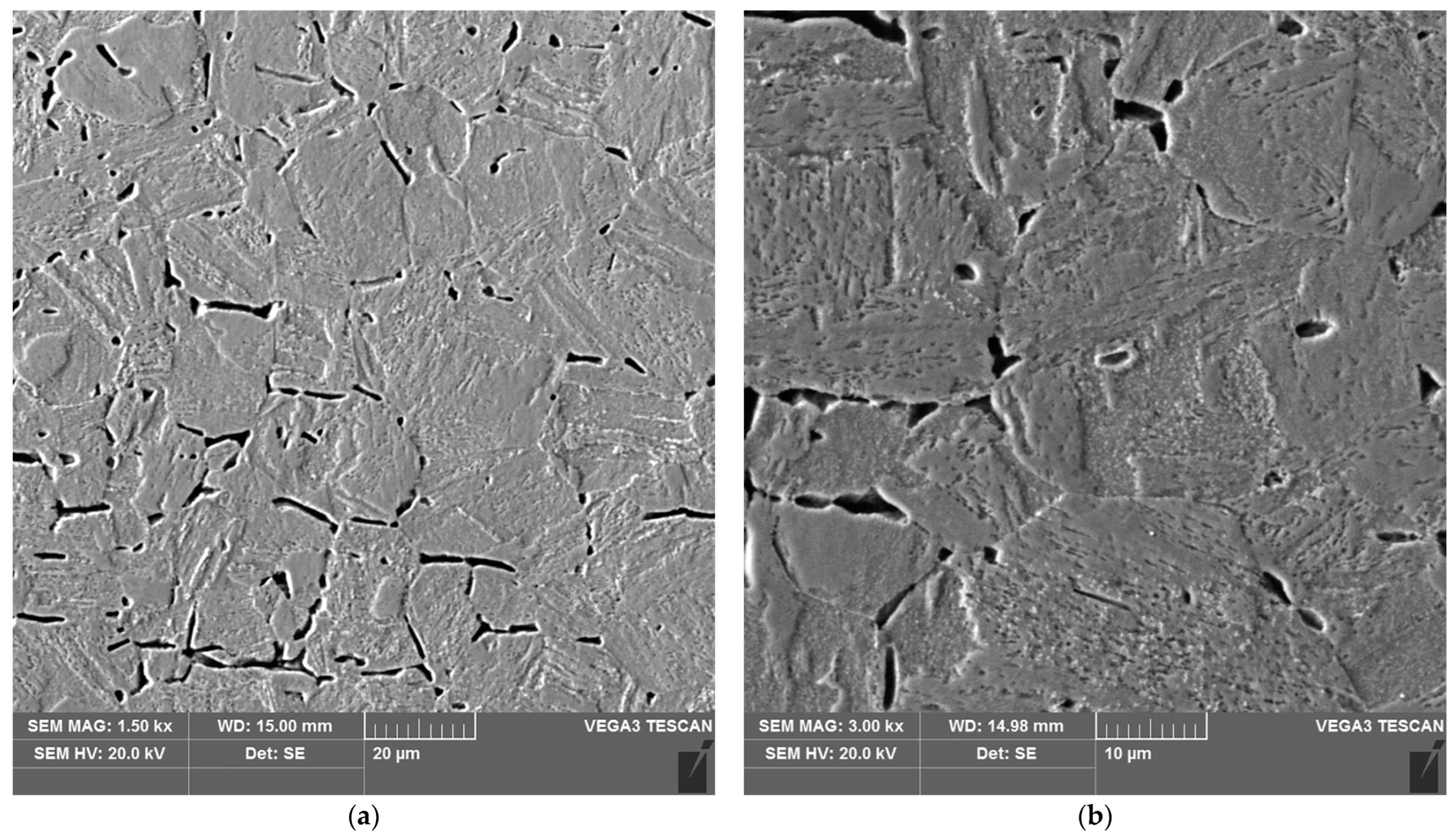
Figure 18.
Microstructure of the heat affected zone in area C of the test joint made manually: (a) magnification 1500×, (b) 3000×. 1–3 are the places where the analysis of the chemical composition was performed.
Figure 18.
Microstructure of the heat affected zone in area C of the test joint made manually: (a) magnification 1500×, (b) 3000×. 1–3 are the places where the analysis of the chemical composition was performed.
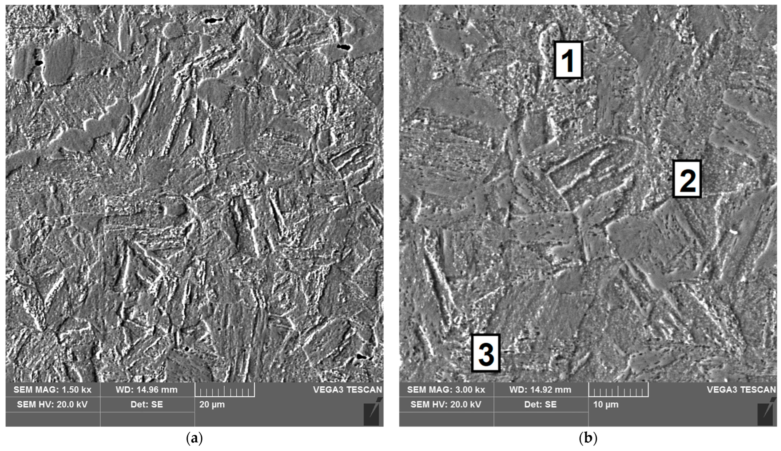
Figure 19.
Microstructure of the heat affected zone in area D of the test joint made manually: (a) magnification 1500×, (b) 3000×.
Figure 19.
Microstructure of the heat affected zone in area D of the test joint made manually: (a) magnification 1500×, (b) 3000×.
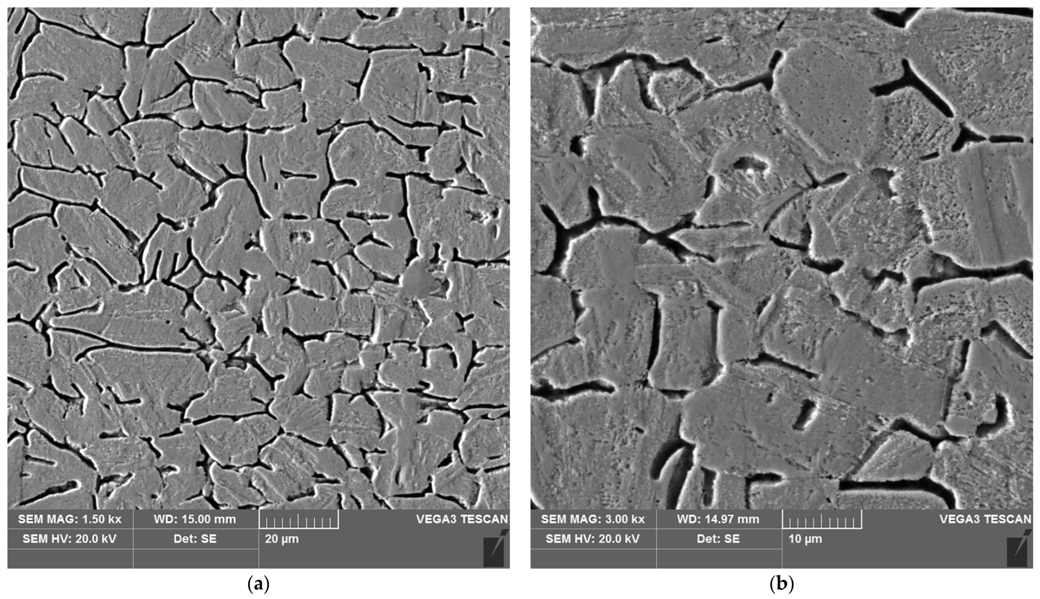
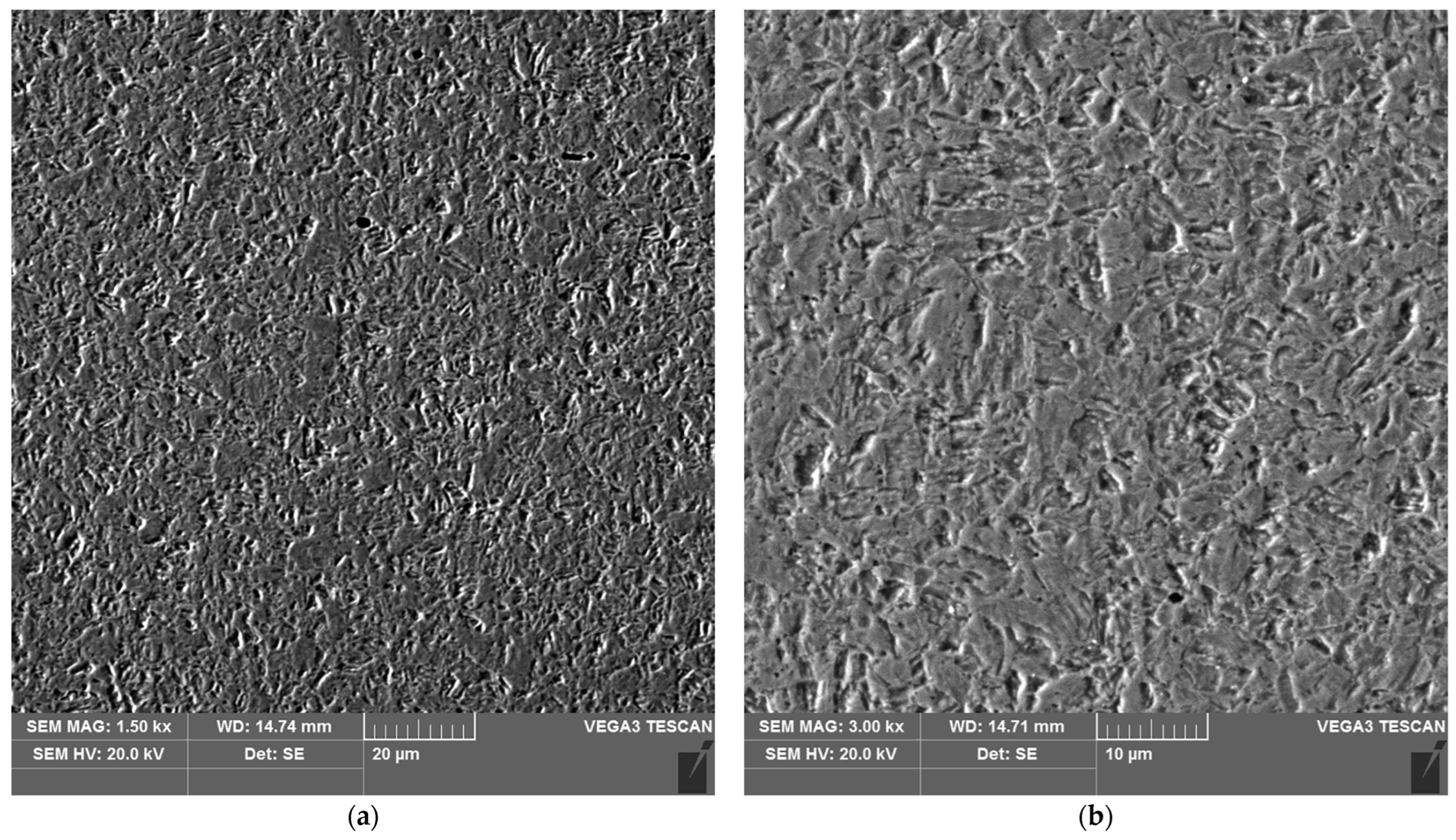
Figure 20.
Microstructure of the parent material area of the test joint made manually: (a) magnification 1500×, (b) 3000×.
Figure 20.
Microstructure of the parent material area of the test joint made manually: (a) magnification 1500×, (b) 3000×.
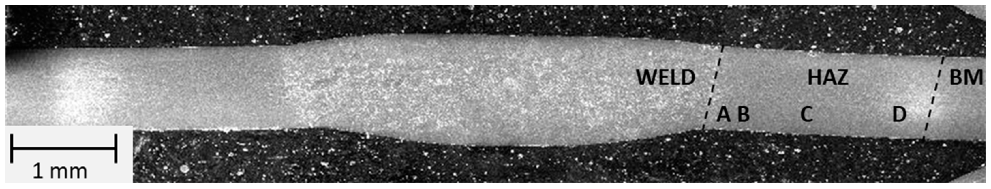
Figure 21.
Macrostructure of the welded joint area of thin-walled 17-4 PH steel components made automatically by TIG method.
Figure 21.
Macrostructure of the welded joint area of thin-walled 17-4 PH steel components made automatically by TIG method.
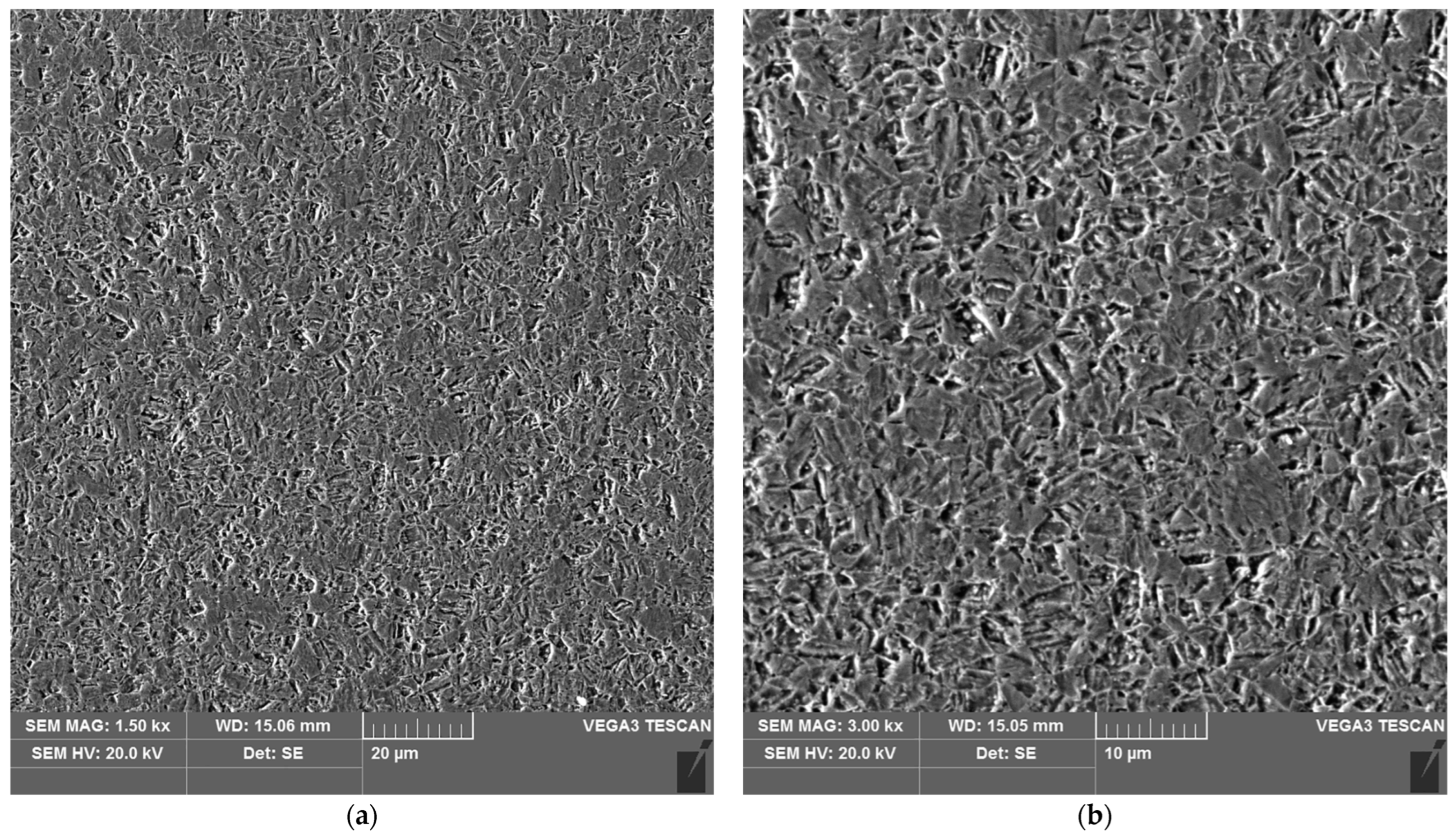
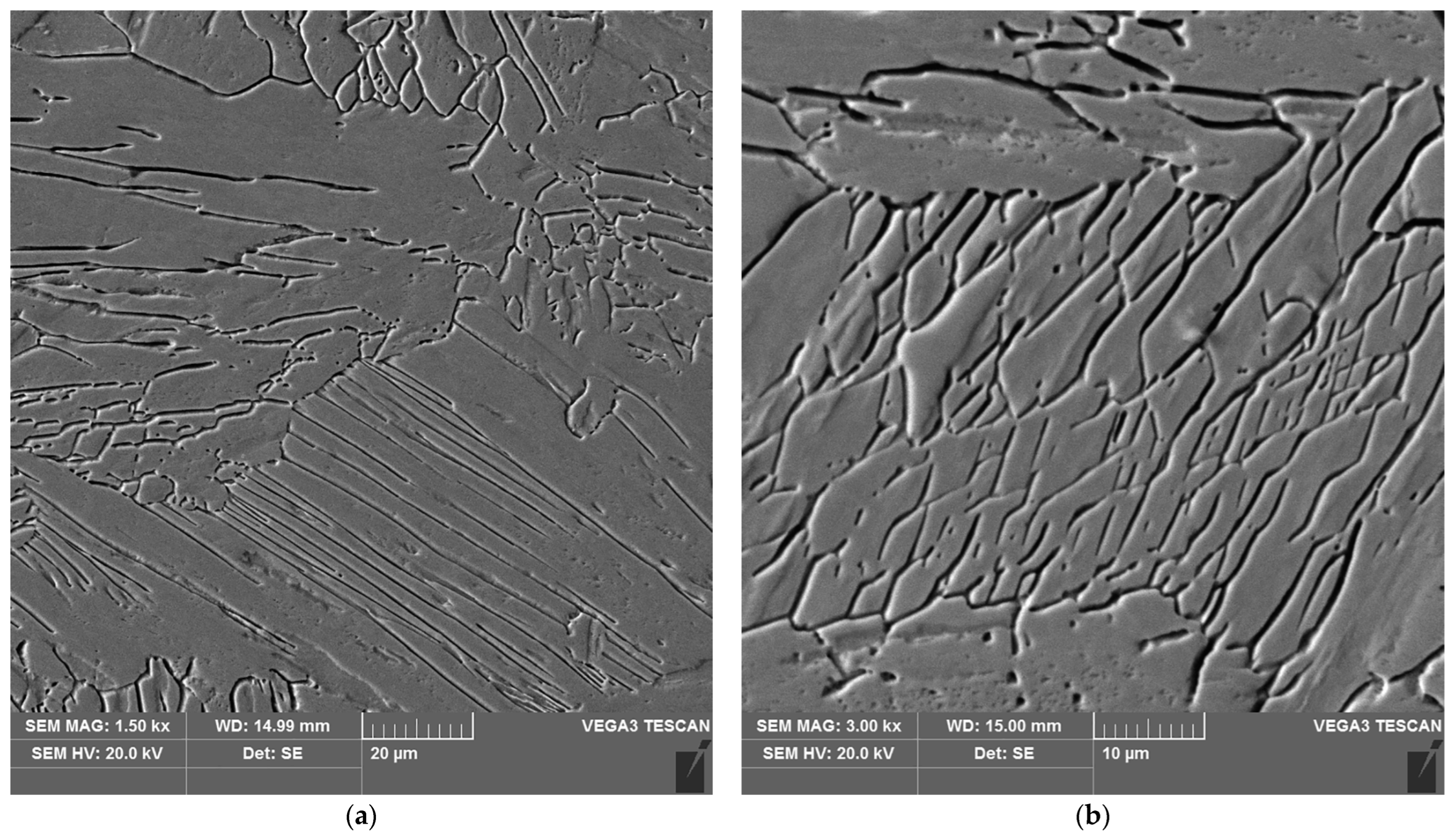
Figure 22.
Microstructure of the weld area of the test joint made by the automated welding method: (a) magnification 1500×, (b) 3000×.
Figure 22.
Microstructure of the weld area of the test joint made by the automated welding method: (a) magnification 1500×, (b) 3000×.
Figure 23.
Microstructure of the heat affected zone in area A of the test joint made by the automated welding method: (a) magnification 1500×, (b) 3000×.
Figure 23.
Microstructure of the heat affected zone in area A of the test joint made by the automated welding method: (a) magnification 1500×, (b) 3000×.
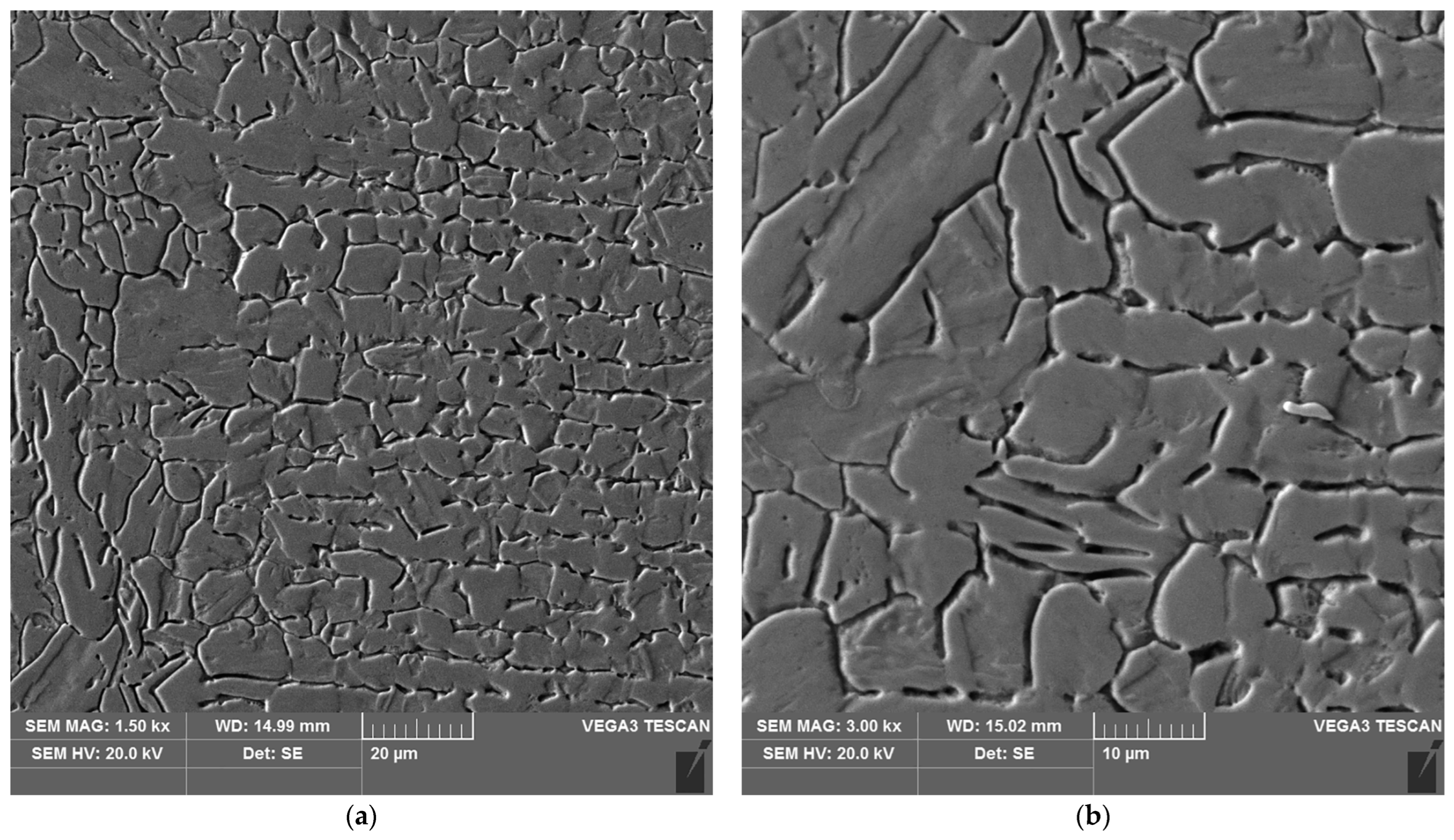
Figure 24.
Microstructure of the heat affected zone in area B of the test joint made by the automated welding method: (a) magnification 1500×, (b) 3000×.
Figure 24.
Microstructure of the heat affected zone in area B of the test joint made by the automated welding method: (a) magnification 1500×, (b) 3000×.
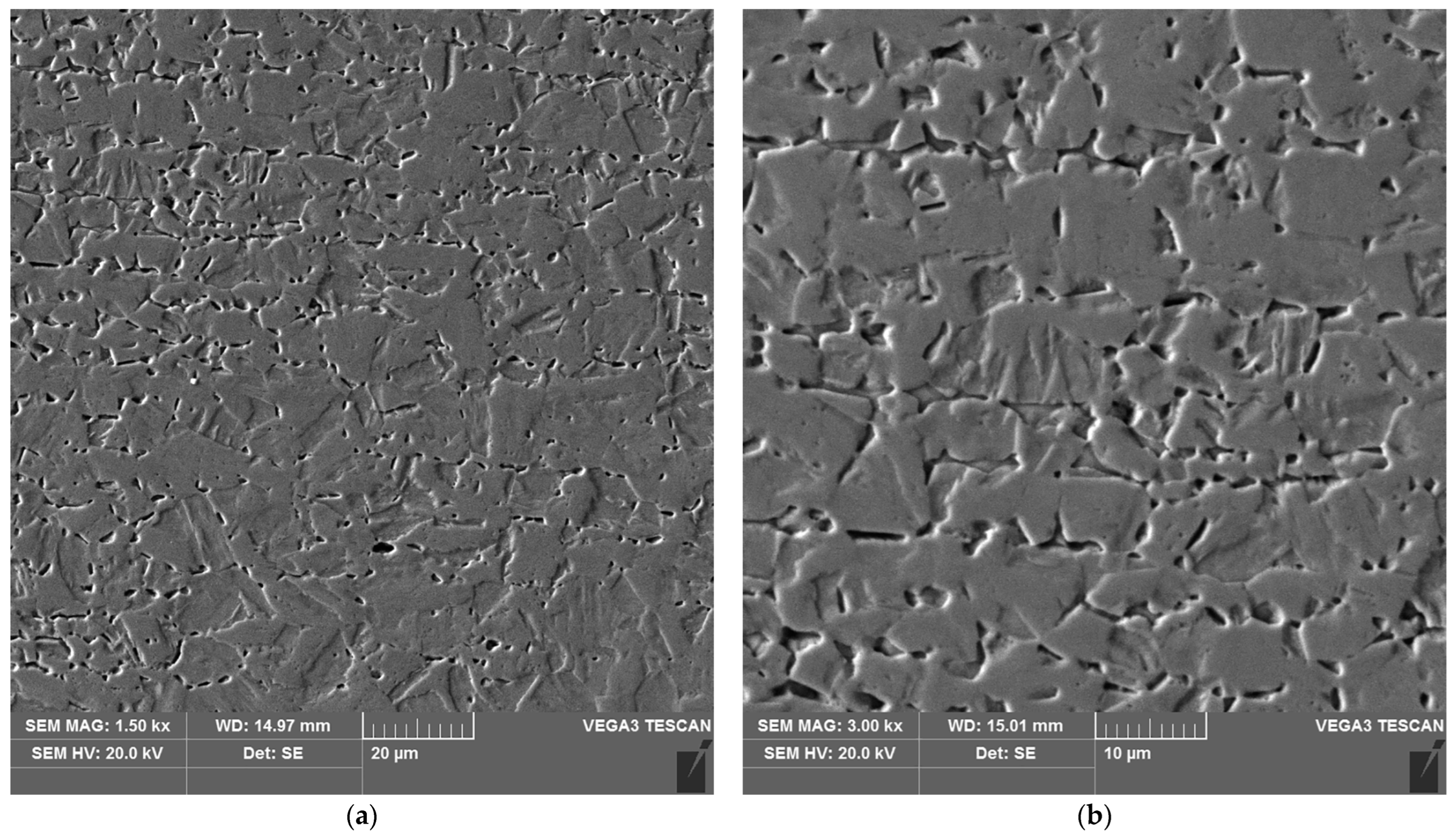
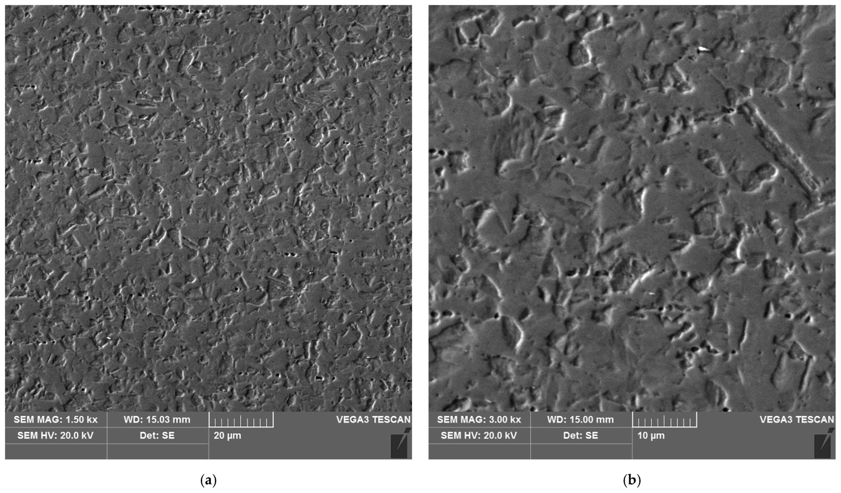
Figure 25.
Microstructure of the heat affected zone in area C of the test joint made by the automated welding method: (a) magnification 1500×, (b) 3000×.
Figure 25.
Microstructure of the heat affected zone in area C of the test joint made by the automated welding method: (a) magnification 1500×, (b) 3000×.
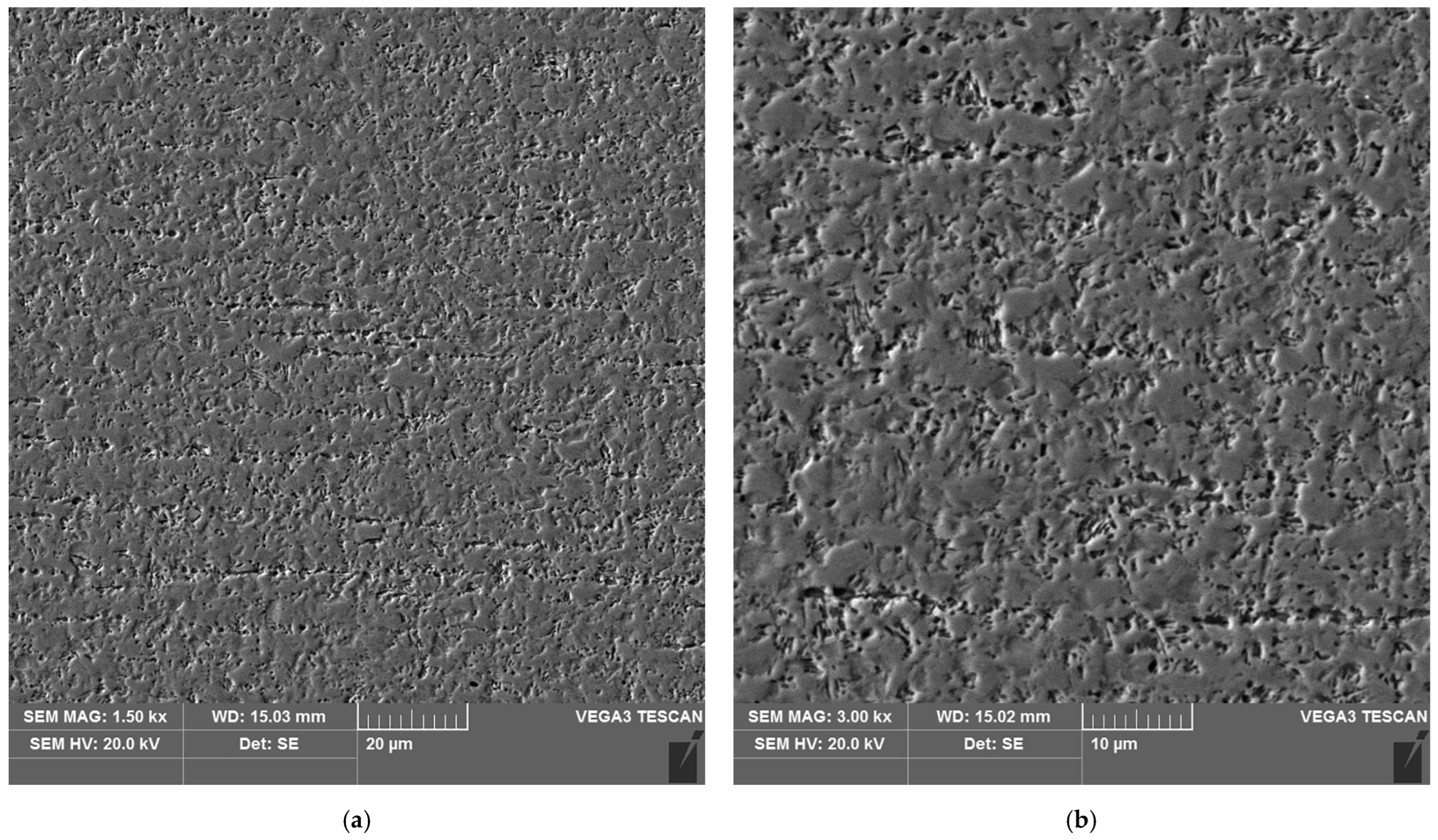
Figure 26.
Microstructure of the heat affected zone in area D of the test joint made by the automated welding method: (a) magnification 1500×, (b) 3000×.
Figure 26.
Microstructure of the heat affected zone in area D of the test joint made by the automated welding method: (a) magnification 1500×, (b) 3000×.
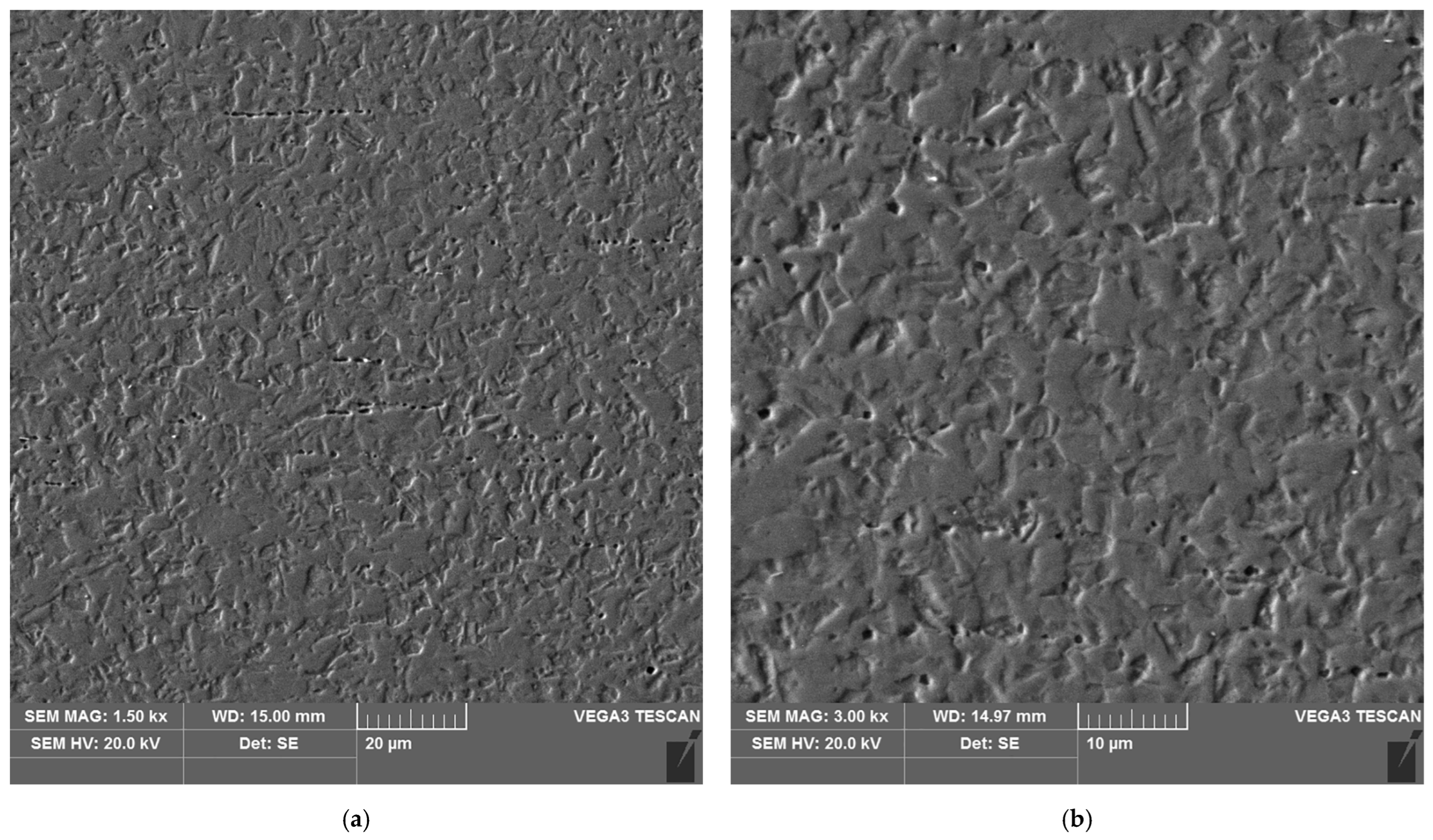
Figure 27.
Microstructure of the parent material area of the test joint made by the automated welding method: (a) magnification 1500×, (b) 3000×.
Figure 27.
Microstructure of the parent material area of the test joint made by the automated welding method: (a) magnification 1500×, (b) 3000×.
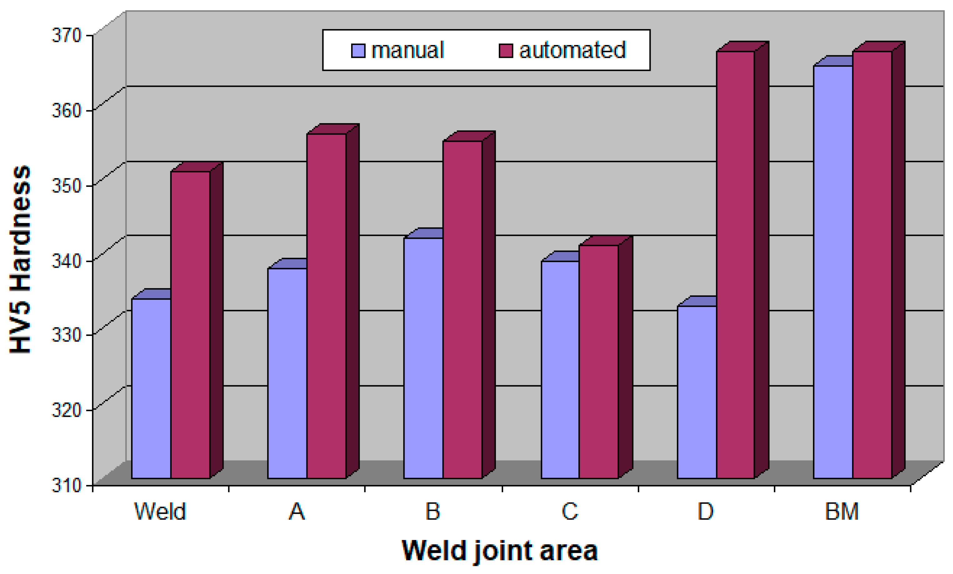
Figure 28.
Hardness of the test joint made by the automated welding method.
Figure 28.
Hardness of the test joint made by the automated welding method.
Table 1.
Chemical composition of 17-4 PH steel.
Table 1.
Chemical composition of 17-4 PH steel.
| Chemical Compositions (%wt.) |
|---|
| C | Si | Mn | P | S | Cr | Mo | Ni |
| 0.052 | 0.376 | 0.511 | 0.084 | 0.0081 | 16.18 | 0.075 | 3.857 |
| Cu | Al | Co | Nb | Ti | V | W | Fe |
| 4.092 | 0.0068 | 0.048 | 0.329 | 0.0075 | 0.059 | 0.029 | 74.24 |
Table 2.
Process parameters of TIG welding of thin-walled components of 17-4 PH steel.
Table 2.
Process parameters of TIG welding of thin-walled components of 17-4 PH steel.
| Parameter | Automated | Manual |
|---|
| Amperage I (A) | 34 | 37 |
| Voltage U (V) | ~8.3 | ~8.1 |
| Welding speed v (mm/min) | 170 | 65 |
| Linear energy (kJ/cm) | 1.00 | 2.8 |
Table 3.
Angular strain values of test joints made manually and automatically.
Table 3.
Angular strain values of test joints made manually and automatically.
| Welding Method | Measurement Point | Angular Strain β (Degrees) |
|---|
| Manual | A | 0.02 |
| B | 0.13 |
| C | 0.21 |
| Automated | A | 0.04 |
| B | 0.26 |
| C | 0.04 |
Table 4.
Results of chemical composition analysis of carbides (
Figure 18b).
Table 4.
Results of chemical composition analysis of carbides (
Figure 18b).
| Point | Chemical Composition [%wt.] |
|---|
| C | Cr | Ni | Cu | Fe |
|---|
| 1 | 2.87 | 16.69 | 4.30 | 2.76 | 73.39 |
| 2 | 2.17 | 16.64 | 4.54 | 3.10 | 73.55 |
| 3 | 1.73 | 16.83 | 4.53 | 2.94 | 73.97 |
Table 5.
Results of measurements of the width of individual areas of the heat affected zone of test joints made manually and by automated welding.
Table 5.
Results of measurements of the width of individual areas of the heat affected zone of test joints made manually and by automated welding.
| Welding Method | Measurement Point | Width of the Heat Affected Zone Area [μm] |
|---|
| manually | A | 120–150 |
| B | 90–105 |
| C | 1800 |
| D | 2000 |
| automatically | A | 90–100 |
| B | 80–90 |
| C | 900 |
| D | 1100 |
Table 6.
HV5 hardness measurements results.
Table 6.
HV5 hardness measurements results.
| Welding Method | Hardness Measurement Point (HV5) |
|---|
| 1 | 2 | 3 | 4 | 5 | 6 | 7 | 8 | 9 | 10 | 11 | 12 | 13 |
|---|
| Manual | 330 | 336 | 366 | 338 | 338 | 344 | 340 | 338 | 340 | 330 | 336 | 366 | 364 |
| average value | 334 in weld | 338 in area A | 342 in area B | 339 in area C | 333 in area D | 365 in BM |
| Automated | 350 | 348 | 355 | 354 | 358 | 356 | 354 | 342 | 340 | 366 | 368 | 368 | 366 |
| average value | 351 in weld | 356 in area A | 355 in area B | 341 in area C | 367 in area D | 367 in BM |


